advertisement

Users Guide
OneSix™ OPC Server
Version 2.2
Copyright ©2004, Point Six, Inc.
Point Six, Inc.
2333 Alumni Parkway.
Suite 305
Lexington, KY 40517
USA
(859) 266-3606 http://www.pointsix.com
Contents
Overview 1
Quick Start .................................................................................................................................1
Description.................................................................................................................................2
Receivers....................................................................................................................................3
Device List .................................................................................................................................4
Polling ........................................................................................................................................4
Identification ..............................................................................................................................4
Filtering......................................................................................................................................5
What is OPC?.............................................................................................................................5
Data Logging..............................................................................................................................5
Diagnostics.................................................................................................................................6
OneSix Main Window 7
Main Window.............................................................................................................................7
Setup ..........................................................................................................................................7
Change Port..................................................................................................................7
Add/Delete IP Connection ...........................................................................................8
View IP Connection Status ..........................................................................................8
Outputs.......................................................................................................................10
Search and Add Devices ............................................................................................11
ReConfigure Net ........................................................................................................11
Device List ...............................................................................................................................11
Errors........................................................................................................................................12
Tools ........................................................................................................................................12
Traffic ........................................................................................................................12
Quit ..........................................................................................................................................12
Help..........................................................................................................................................12
OneSix Server .INI File Format 13
OneSixOPC.ini.........................................................................................................................13
SERVER ....................................................................................................................14
Logging......................................................................................................................15
IP Addesses................................................................................................................15
DIGITAL I/O.............................................................................................................15
TEMPERATURE Setup ............................................................................................16
HUMIDITY ...............................................................................................................17
DIGCOUNTER and Directional Counter ..................................................................18
CNTTEMP.................................................................................................................18
FASTCNTTEMP.......................................................................................................20
ALARMTEMP ..........................................................................................................21
Analog Input ..............................................................................................................22
Access/Control Reader...............................................................................................23
OneSix Server Help Contents x i
ii x Contents
Repeater .................................................................................................................... 23
Dual Discrete Output................................................................................................. 24
Wireless Analog Output............................................................................................ 25
OneSix INI Backup ................................................................................................................. 26
OneSix Server OPC Tags 27
Using OPC Tags...................................................................................................................... 27
Device Names.......................................................................................................................... 27
Device Tag Names .................................................................................................................. 29
DIGCOUNTER and Directional Counter: DIGCOUNTERn and DIRECTCNTn ... 32
FASTCNTTEMP: FASTCNTTEMPn...................................................................... 34
Server Item Names .................................................................................................................. 42
OneSix Server Data Logging 44
TCP/IP Receivers 48
Error Messages 50
No Devices Attached! ............................................................................................... 50
Cannot Open Communication Port; Already In Use. ................................................ 50
Corrections
52
OneSix Server Help
OneSix Server Help Contents x iii
Overview
Quick Start
When OneSix is run for the first time it displays this help screen. You may view this help screen again by selecting "Help" from OneSix's main window.
OneSix is designed to gather data from sensors. OneSix makes available the data it receives from each sensor through OPC tags.
The Main OneSix™ Server window will show the total number of devices in the startup list and how many of those that are online. The offline devices will be shown in the list box at the bottom of the window.
OneSix™ can be a stand-alone data logger. When data logging is enabled, OneSix™ will store collected data in an ASCII file at a programmable interval. See section
"OneSix Server Data Logging".
This Help and all other Help topics may be accessed from the main window by selecting Help or pressing F1.
Setup
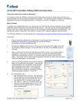
x Plug the reciever into your serial port x Start OneSix.
x If necessary, tell OneSix what kind of Receiver you are using.
x When the "Add Wireless Device" screen appears, press the service mode button on your transmitter to transmit a packet that OneSix can see.
x When a device appears in the window, you may click to select it and then press the 'Edit' button to change its label name and transmit time.
x Press OK to add these sensors to the OneSix list x OneSixOPC will create OPC tag objects for each device and start polling and gathering data from each device.
OneSix Server Help Overview x 1
Description
2 x Overview
If there is not an OneSixOPC.ini file or if [Server]NumberDevices=0 and when
OneSix™ starts, it will automatically prompt for devices on the network and add them to its list of devices to process.
OneSix™ is a data acquisition OLE for Process Control (OPC) server that acquires data from devices and passes this data using OPC to a client application. OneSix waits for the device to transmit and then processes the transmission.
Any Windows® application that can use OPC can obtain this data from the
OneSix™Server. Examples of such applications include Wonderware® Intouch,
National Instruments® LookOut, and general development applications like
Microsoft® Visual Basic and Borland® Delphi.
OneSix™can be a stand-alone data logger. When data logging is enabled,
OneSix™will also store collected data in an ASCII file at a programmable interval.
Another program such as a spreadsheet or a database manager can import the data.
See section "OneSix Server Data Logging".
OneSix Server can receive transmissions from wireless devices such as the wireless temperature transmitter. Other devices include the wireless humidity sensor and wireless analog input. OneSix uses a wireless receiver such as the Point Repeater, the Point Host or the PointView Receiver to receive transmissions from wireless sensors. OneSix can also use multiple TCP/IP Receivers (Point Managers in Pass-
Thru mode) to receive data through TCP/IP connection.
When setting up a wireless network, OneSix passively waits for transmissions instead of actively polling for devices. This can make the acquisition of sensors take a longer time than for a wired network as OneSix must wait for the device to transmit.
You can speed up this process by pressing the service button on the device so that it transmits while you are in the “Add Sensors” screen.
Each device has an entry in the device's INI file section. Each device has a
"repeateraddress" attribute. When running OneSix with a Point Repeater, the
Repeater ID is stored in the "repeateraddress" entry. The value in the
"repeateraddress" indicates which Point Repeater sent the sensor information With all other wireless receivers, the "repeateraddress" is set to 0. Finally, the INI entry and OPC tag "Polltime" for each device has a different meaning when working with wireless transmitters. OneSix cannot poll the wireless sensors. It must wait for a transmission. Therefore, OneSix uses polltime to estimate how frequently a transmission should come from a device. It also uses a multipler of this time to determine if a device is offline. This multipler is configurable by the user.
Setup Described
OneSix will display the “Add Sensors” screen when it starts for the first time. The setup screen is the method by which OneSix acquires wireless devices. The default on the setup screen is to accept only packets that are sent in service mode from the device (the packet is sent by pressing the service button on the device.) To change this default, uncheck the "Service Mode Only" checkbox. OneSix will then display all the packets it receives. When OneSix receives a packet from a device new to it, it names the device following the naming conventions detailed below, and it displays the device's name and serial number in the window.
You have several options after the device has been displayed. The "Clear New" button will clear all the devices that have just been received. The "Delete" button
OneSix Server Help
Receivers
will delete a single device. Click on a device to select it and click on "Delete" to delete it. To edit a device click on the device to select it and click on "Edit" to edit the device. There is also a "Stop" button. If you click that button, OneSix will stop listing devices in the window. When you click on the "Stop" button it becomes a
"Receive" button. If you click on that, OneSix will start receiving packets and listing devices again.
When you are ready, hit "OK", or "Cancel" to exit.
Edit Device
The Edit screen for a new wireless device shows the device's serial number, which the user cannot change, the device's current Label, which can be changed by the user, and the Transmit Rate for the device. The Label cannot be the same as the label used by any current device. The Transmit Rate is in seconds. The default value is
60. OneSix uses the Transmit Rate to determine if a device has gone offline.
The following is a list of the receivers that OneSix can use: x Point View Receiver x Point Host Receiver x Point Integrator Logger –select "Point Host Receiver" from the "Select
Communication Port" screen x Point Repeater and Repeater III – select "Point Host Receiver" and set the TZR baud rate to 19,2000.
x TCP/IP Receiver (Point Manager in “Pass-Thru” mode)
OneSix Server Help Overview x 3
Device List
OneSix™ Server interfaces to a large number of devices. New devices are continually being created for the Wireless network. Check with your distributor for the latest.
The following is a list of devices supported by OneSix™ Server:
Point Sensor Temperature
Point Sensor Temp/Humidity
Point Sensor Analog 5V
Point Sensor Analog 10V
Point Sensor Analog 20mA
Point Probe
Point Sensor Pressure
Point Sensor DSCI
Point Sensor IR Counter
Point Sensor Thermistor
Point Sensor Counter Temperature
Point Sensor Fast Counter Temperature
Point Sensor Alarm Temperature
Point Access/Control Reader
Point Directional Counter
Point Dual Discrete Output
Point Analog Output
Polling
The polltime has a slightly different meaning for wireless sensors. OneSix does not actively poll wireless devices. Rather, it waits to receive a packet from the devices.
Therefore, the polltime is how often OneSix expects to receive a packet from the wireless devices.
The polltime for a wireless device is configurable during device setup. OneSix will use this time to determine when to mark a device offline. OneSix has a INI file parameter called "Tries" that sets how long a device has to transmit before it is considered offline. For example, if the device has a polltime of 1 minute, and
OneSix has "tries" set to 3, then OneSix will consider the device offline if it does not receive a packet from that device in 3 minutes ("tries" times "polltime").
Identification
OneSix™ identifies each device with a unique label name. A client application uses this label (an OPC topic) to obtain data from the server.
4 x Overview OneSix Server Help
Filtering
For both analog and temperature devices, OneSix™ allows the user to define a deadband to control the amount of change that must occur before the server updates a
Client with new data. Deadband is useful to control the amount of information that is passed through OPC to the client application. For analog devices, the deadband is entered as the percentage of full scale of Engineering units. For temperature devices, the deadband is entered in degrees C.
Also for both analog and temperature devices, One Six™ provides the means to filter the data with either an Average, Median or combination Median Average filter before either logging data or delivering data through OPC. In the One Six INI file, you specify the filter type and the number of samples to filter.
What is OPC?
OLE for Process Control (OPC) is a specific specification of Microsoft’s Object
Linking and Embeddeding (OLE) and Component Object Model (COM) that is administered by the OPC Foundation (150 member companies including Microsoft
Corporation). OPC provides a common interface for devices and applications to communicate. Devices that gather or originate data become OPC servers, providing data to OPC client applications in a consistent fashion. At the heart of OPC is the client/server model in which the OPC server provides and interface to the OPC object, allowing client applications to control devices and manage device data in a generic fashion. OPC servers can be accessed through most HMI software and through a variety of languages, including C++, Visual Basic, and Delphi. The OPC server collects data from physical devices for distribution to OPC client applications and also has the responsibility for updating device data when an OPC client issues a write.
An OPC client connects to and communicates with an OPC server through one of two interfaces defined in the OPC specification. The OLE automation interface allows users to access data through the use of a common, easily understood scripting language. The COM interface is more complex, but provides finer levels of control and flexibility for developers and users proficient in languages such as C or C++.
OPC client applications can access OPC servers locally within a computer or from a networked server.
Data Logging
OneSix™ Server can log data to an ASCII file at a programmable interval. The default name of the file is ONESIX.LOG.
A client application can control logging through OPC variables. The client can start/stop logging or just log a single record.
For diagnostic purposes, OneSix™ can log errors that have occurred while waiting or process device data.
For more information see the section OneSix Server Data Logging.
OneSix Server Help Overview x 5
Diagnostics
With OneSix™, you can monitor the health of your wireless and the devices attached.
OneSix™ reports through OPC errors that it encounters while polling devices. These errors can be noted in an event error log. See the section called "Server Item Names" for more information.
6 x Overview OneSix Server Help
OneSix Main Window
Main Window
OneSix™ displays the number of devices online and offline. It also lists the devices that are currently offline displaying the name and serial number of the device. If
OneSix™ is running with TCP/IP receivers, then for each offline device it will display the node address, name and serial number of the device.
Setup
OneSix™ simplifies setup by automatically finding, identifying and beginning to poll devices in a network. OneSix™ assumes default initial values. You can easily change these values by editing the ONESIXOPC.INI file with an ASCII text editor. (The installation program for OneSix™ Server created a short cut to the ONESIXOPC.INI file. Double clicking will automatically start WordPad or Notepad.) See the section
"OneSix Server .INI File Format".
Change Port
The Change Port submenu allows you to switch to another wireless receiver port.
When the Change Port submenu is selected, OneSix™ displays the Select
Communication Port window. Choose one of the following:
AUTO - instructs OneSix™ to search Port Numbers 1 to 4 for the
PointView Receiver.
PointView Receiver
Point Host
TZR Transceiver – (Point Transceiver) – make sure the TZR baud rate is set to 19200.
TCP/IP Receiver – uses a receiver that uses the TCP/IP protocol to receive sensor packet data. (Point Manager in “pass-thru” mode).
When OK is clicked, OneSix™ tries to initialize the port. For the PointView and
TCP/IP Receivers, OneSix confirms that the receiver is present. For the Point Host and the TZR Transceiver, OneSix assumes the receiver is present. If OneSix™ fails,
OneSix™ displays the OneSix Initializing Error Window allowing you to retry, select another port or exit OneSix™. If OneSix™ succeeds, OneSix™ starts listening and processing sensor packets.
OneSix Server Help OneSix Main Window x 7
8 x OneSix Main Window
Add/Delete IP Connection
(TCP/IP Receiver only)
OneSix will display the “Add/Delete IP Connection” screen. IP addresses already setup will be displayed. The following is a list of the columns:
Node – Node number for the IP address. OneSix uses this number to identify this IP connection. OneSix uses this number to update the OPC tag item “nodaladdress”.
IP Address – the IP address that is used to address the receiver.
Port – the port number that is used along with the IP address to address the receiver.
Conn – identifies who initiated the connection. Outgoing: OneSix initiated the connection with the receiver. Incoming: the receiver initiated the connection with OneSix.
Password – initial password used to gain access to the receiver.
Description – a general description field associated with the IP connection.
The following is list of buttons in the “Add/Delete IP Connection” screen:
Test – OneSix will try to make a connection to this IP address and report back success or failure.
Add New – OneSix displays the “New IP Address” screen. The following is list of the fields to enter to add a new IP connection:
IP Address – the IP address that is used to address the receiver
Port – the port number that is used along with the IP address to address the receiver.
Description– a general description field associated with the IP connection.
Password – initial password used to gain access to the receiver. If the receiver does not have a password set or does not require a password then leave this field blank.
Connection – identifies whether OneSix will initiate the connection or whether the receiver will initiate the connection. Outgoing: OneSix initiates the connection. Incoming: OneSix waits for the receiver to initiate the connection.
Edit – OneSix displays the “Edit” screen showing the selected IP connection. The “Edit” screen has the same fields as the “New IP
Address” screen.
Delete – delete the selected IP connection.
View IP Connection Status
(TCP/IP Receiver only)
OneSix will display the “IP Status” screen. OneSix shows the current state of the all the connections. The following describes the columns:
OneSix Server Help
Node – Node number for the IP address. OneSix uses this number to identify this IP connection. OneSix uses this number to update the OPC item “nodaladdress”.
IP Address – the IP address that is used to address the receiver.
Port – the port number that is used along with the IP address to address the receiver.
Conn – identifies who initiated the connection. Outgoing: OneSix initiated the connection with the receiver. Incoming: the receiver initiated the connection with OneSix.
Description – a general description field associated with the IP connection.
Status – the current status of the connection. The following is a list of the possible status messages:
Never Connected – OneSix never attempted or received a connection to the receiver
IP Connected – OneSix is currently connected to the receiver but has not logged in.
Connected – OneSix is currently connected to the receiver is waiting to receive sensor packets.
Disconnected – OneSix was connected but is now disconnected from the receiver. If the connection was initiated by OneSix, OneSix will continually try to reestablish the connection.
TCP/IP Error – a TCP/IP error was encounter and OneSix is not connected to the receiver.
No IP Connection – OneSix tried to establish a connection but failed.
Wrong Password – The receiver requires a login password and the incorrect password was used by OneSix.
OneSix Server Help OneSix Main Window x 9
10 x OneSix Main Window
Outputs
OneSix can send output packets to output devices. (Normally sensors do not receive packets) Output devices must be setup manually. Some Outputs need to be “trained” to the packets that it will receive for from the Server.
New and Edit
Create or edit an Output object to manage an Output sensor. The following describe the parameters necessary to set up an Output sensor.
Type – “Dual Discrete Outputs” or “12 bit Analog Output”. Select the type of Output sensor. Note changeable only for the Edit Output window.
Serial Number – Some Outputs sensors can “learn” a serial number. Others have the serial number preassigned and must be entered in the field.
These sensors have the serial number labeled. For those sensors that must learn their serial number, OneSix creates a default serial number.
Press the “Generate New Serial Number” button to generate a new serial number.
Label – name assigned for this Output sensor. The label name is used for the OPC topic name. This name must be unique. For the Edit Window, the Label field contains a list box. Select the Output to modify from the list. You can also change the label for the current Output.
Node – This field applies only when using the TCP/IP Receiver. The Node
List box contains a list of the TCP/IP Receivers to send the output packet to. For the “Send All” selection, OneSix will send the packet to all the TCP/IP Receivers.
Dual Discrete Outputs
Send when output B is written – If checked, OneSix will only send the output packet only when the “outputB” item is written to. Output A is first written to and the output B. If unchecked, OneSix will send the output packet when either the “outputA” or “outputB” items are written to. The state both outputs are sent in the same packet.
12 bit Analog Output
Scale – the scale to apply to the raw reading (12 bits: 0 to 4095).
Offset – the offset to apply to the reading after the scale is applied.
Engeering Value = Scale * raw + Offset.
Units – units label for the analog output.
Train
The Train dialog is used in the processing of training the Output device to output packets (as produced by OneSix). Follow these steps to train an Output device:
1. Select the desired Output from the list of Outputs.
2. Press and hold the button on the Output device (label as “train”).
3. Click the button on the Train window. Repeat until the LED on the
Output device is on.
The Output device is now ready to receive Output packets from OneSix.
OneSix Server Help
Device List
Search and Add Devices
OneSix will display the "Add Sensors" screen. Devices already in the
OneSixOPC.ini file are displayed in the top portion of the screen. Follow the setup procedure to add more devices.
The setup screen is the method by which OneSix acquires wireless devices. The default on the setup screen is to accept only packets that are sent in service mode from the device (the packet is sent by pressing the service button on the device.) To change this default, uncheck the "Service Mode Only" checkbox. OneSix will then display all the packets it receives. When OneSix receives a packet from a new device new, it names the device following the naming conventions detailed below, and it displays the device's name and serial number in the window.
You have several options after the device has been displayed. The "Clear New" button will clear all the devices that have just been received. The "Delete" button will delete a single device. Click on a device to select it and click on "Delete" to delete it. To edit a device, click on the device to select it and click on "Edit" to edit the device. There is also a "Stop" button. If you click that button, OneSix will stop listing devices in the window. When you click on the "Stop" button, it becomes a
"Receive" button. If you click on that, OneSix will start receiving packets and listing devices again.
When you are ready, hit "OK", or "Cancel" to exit.
Edit Device
The Edit screen for a new RF device shows the device's serial number, which the user cannot change, the device's current Label, which can be changed by the user, and the Transmit Rate for the device. The Label cannot be the same as the label used by any current device. The Transmit Rate is in seconds. The default value is 60.
OneSix uses the Transmit Rate to determine if a device has gone offline.
ReConfigure Net
OneSix™ clears device information from the OneSixOPC.ini file and shows the
“Add Sensors” screen. Use caution here; all changes that you have made manually to the device information contained in the OneSixOPC.ini file will be deleted and overwritten. OneSix™ does not modify the global configuration parameters contained in the sections Server and Logging of the OneSixOPC.ini file.
Clicking this menu option shows the “View Device List” window. OneSix™ shows a list of devices and their serial numbers.
To see the help for a device, click on the device and then click the help button.
OneSix™ will display the help for the selected device.
OneSix Server Help OneSix Main Window x 11
Errors
Tools
Quit
Help
OneSix™ displays the Communication Errors window. This window shows the last error that occurred.
Tries Count: Number of tries that have occurred before a device is considered offline.
Major Error Count: Number of errors that (after tries) took the device offline.
Last Error Code: Number error code of the last error
Last Error Device: The name of the device that had the last error.
Last Error Time: The time when the last error occurred.
Last Error Message: A description of the last error.
Click the Reset button clear the errors and reset the counts.
Traffic
The Traffic program is utility to monitor the traffic flow of sensors through the wireless network. Use the utility to monitor the health of the sensors and make adjustments to receivers, repeaters and sensors.
When you select this menu option, OneSix™ terminates.
You select the the Help file's contents or index window or you can display the
OneSix™ About window.
12 x OneSix Main Window OneSix Server Help
OneSix Server .INI File Format
OneSixOPC.ini
The ONESIXOPC.INI file contains the configuration parameters for the server and and a list of devices to process. When OneSix™ searches and finds a new device it adds the device to the INI file and assigns default initial parameters. These parameters can be changed by using a text editor and editing the INI file. The installation program for OneSix™ Server created a short cut to the ONESIXOPC.INI file. Double clicking will automatically start WordPad or Notepad. The following rules must be kept when editing the INI file.
1) All device label names must be unique.
2) The NumberDevices in the [Server] section must equal the largest device section [Devicen].
3) The must be no missing device sections [Devicen] in the list.
Note: OneSix™ looks at the ini file only at startup or after adding a new device.
Changes made to the ini file will not be reflected in OneSix™ until OneSix™ is closed and restarted.
OneSix Server Help OneSix Server .ini File Format x 13
The following is a list of the ONESIXOPC.INI parameters.
SERVER
[Server]- Section name.
PortType - Communication medium (AUTO, Point Host, TZR, Point View, etc.).
PortNo - Port number.
NumberDevices - Number of devices to be processed by the server.
Tries - No. of tries during polling before a device is marked offline.
HostAdapterCheck - Enables/disables the detection of receiver. (0 or 1)
BaudRate –options are: 115,200; 38,400; 19,200; or 1200. The default is
19200. Use this parameter for receivers that use a different baud rate than the default. Make sure the value in the ini file matches the value set in the hardware.
DefaultTempUnits - specifies the starting units of Temperature devices
DefaultPressUnits - specifies the starting units of Pressure devices
DefaultForceUnits - specifies the starting units of Force and Scale devices
ConfigureEnable – 0 – disables the Setup Menu option on the main menu.
The user then cannot make any changes to the configuration. 1 –
(default) – enable the Setup Menu option on the main menu.
SmallINI – suppresses the listing of minor variables in order to make the ini file smaller. Note that Windows 98 and ME have a limit of 64K bytes for the INI file size.
DefaultThermistorCorrID – overrides the default thermistor Correction ID
(normally 128). All thermistors will be assigned this Correction ID unless the ID is overridden in the individual device section.
ForwardAll – species if all packets are forwarded or only packets associated with OneSix’s device list get forwarded across a TCP/IP connection. A TCP/IP client must initiate the connection to the port specified with the ForwardPort in the [IP Addresses] section. Each packet has the following format: sensor packet,node number, node description, sensor label.
ValueOffline – 0 – I/O parameters will retain the last value when the sensor goes offline; 1 – I/O parameters will be set to a value of –999999 when a sensor goes offline.
14 x OneSix Server .ini File Format OneSix Server Help
OneSix Server Help
Logging
[Logging] - section name
LogRate - 0: no logging; 1-100000 logging interval in seconds. 5 sec or greater OneSix™ opens and closes the log file at every logging interval.
Less than 5 OneSix™ leaves the file open until OneSix™ is terminated or
“Server.Logging.LogRate” is set to 0 or 5 and greater.
LogFile - full pathname for the log file - default "ONESIX.LOG"
OfflineIndicator - character or string to indicate offline - NULL: last value
LogErrors - 1 - log runtime network errors to ONESIX.ERR. 0 - do not log errors
IP Addesses
[IP Addresses] – section name (for TCP/IP receivers)
IPWaitPort – port number that OneSix will wait for connections initiated by an IP receiver. (default is 1060)
ForwardPort – port number that OneSix will wait for connections to forward received packets. (default is 0 which means disabled) OneSix will forward received packets through this connection. Each packet has the following format: sensor packet,node number, node description, sensor label. The INI parameter FowardAll in the [Server] section controls what packets get sent.
DIGITAL I/O
[Devicen] - Section name.
Address – serial number of the sensor.
DeviceType - Device type. (DeviceType=DIGITAL)
PollTime – the transmit interval of the sensor. (ms)
Label - Name used for the device (and Topic).
Log - Enable/disable logging of device.
OutputOnDemand - Output is initiated on demand or during poll.
DescriptionA - General purpose description.
DescriptionB - General purpose description.
OneSix Server .ini File Format x 15
TEMPERATURE Setup
(Point Temperature, DS1820/1920/18S20/18B20/1822)
[Devicen] - Section name.
Address - – serial number of the sensor.
DeviceType - Device type. (DeviceType=TEMP)
PollTime - the transmit interval of the sensor. (ms)
Label - Name used for the device (and Topic).
Log - Enable/disable logging of device.
LogDecimalPlaces - Number of decimals to create when logging.
Units - See OPC tags list under input.units for description.
Cal1Raw - Two point calibration point 1.
Cal2Raw - Two point calibration point 2.
Cal1Engr - Two point calibration engineering units for point 1.
Cal2Engr - Two point calibration engineering units for point 2.
DeadBand - Dead band filtering value in ºC. (Default 0.01)
FilterElements - running macro filter of the sampled data. Syntax: [no. of elements, type] where no. of elements is number of samples to filter; type – “AVERAGE”, “MEDIAN” and “AVERAGEMEDIAN”.
Default is “=0,MEDIAN” – no filtering. Example:
FilterElements=6,AVERAGE
Description - General purpose description.
CorrID – What CorrectionID to use with this device. Must be found in the
"Correction.INI" file that you write and keep in the same directory as the OneSix.ini file. 0 is the default and means no correction; 127 is the maximum. If the device type is a thermistor, the default CorrID is found in the [Server] section "DefaultThermistorCorrID", which defaults to 128.
16 x OneSix Server .ini File Format OneSix Server Help
OneSix Server Help
HUMIDITY
[Devicen] - Section name.
Address - – serial number of the sensor.
DeviceType - Device type. (DeviceType=HUMIDITY)
PollTime - the transmit interval of the sensor. (ms)
Label - Name used for the device (and Topic).
Log - Enable/disable logging of device.
LogDecimalPlaces - Number of decimals to create when logging.
PollSamples - No. of samples per poll (must be odd no.) If >0 Median Filter if <0 then Average Filter is used.
Temperature - Indicates if sensor needs temperature compensation. (0 or
1).
DeadBand - Dead band filtering value in % of full scale.
Description - General purpose description.
Cal1Raw - Two point calibration point 1.
Cal2Raw - Two point calibration point 2.
Cal1Engr - Two point calibration engineering units for point 1.
Cal2Engr - Two point calibration engineering units for point 2.
Units - % Relative Humidity
TempCoeff - PPM temperature coefficient of the sensor.
TempCalib - Temperature at which the calibration was done.
TempAddress – serial number of the temperature sensor in the probe.
MacroFilterElements - running macro filter of the sampled data. Syntax:
[no. of elements, type] where no. of elements is number of samples to filter; type – “AVERAGE”, “MEDIAN” and “AVERAGEMEDIAN”.
Default is “=0,MEDIAN” – no filtering.. Example:
MacroFilterElements=6,AVERAGE
CorrID – What CorrectionID to use with this device. Must be found in the
"Correction.INI" file that you write and keep in the same directory as the OneSix.ini file. 0 is the default and means no correction; 127 is the maximum.
OneSix Server .ini File Format x 17
DIGCOUNTER and Directional Counter
[Devicen] - Section name.
Address - – serial number of the sensor.
DeviceType - Device type. (DeviceType=DIGCOUNTER or
DIRECTCNT)
PollTime - the transmit interval of the sensor. (ms)
Label - Name used for the device (and Topic) (typically DIGCOUNTER1 or DIRECTCNT1).
Log - Enable/disable logging of device.
LogDecimalPlaces - Number of decimals to create when logging.
ScaleA - Multiplier for Counter A
ScaleB - Multiplier for Counter B
UnitsA - Generic label for units - no function
UnitsB - Generic label for units - no function
DescriptionA - Generic description field
DescriptionB - Generic description field
EnableCounterB - Enable the gather of Counter B
Description – General purpose description field
CNTTEMP
[Devicen] - Section name.
Address – serial number of the sensor.
DeviceType - Device type. (DeviceType=CNTTEMP)
PollTime - the transmit interval of the sensor. (ms)
Label - Name used for the device (and Topic) (typically CNTTEMP1).
Log - Enable/disable logging of device.
LogDecimalPlaces - Number of decimals to create when logging.
Scale - Multiplier for Counter A
Units - Generic label for units - no function
Description - Generic description field
temp.Units - See OPC tag item temp.input.units for description.
temp.Cal1Raw - Two point calibration point 1.
temp.Cal2Raw - Two point calibration point 2.
temp.Cal1Engr - Two point calibration engineering units for point 1.
temp.Cal2Engr - Two point calibration engineering units for point 2.
temp.DeadBand - Dead band filtering value in ºC. (Default 0.00)
18 x OneSix Server .ini File Format OneSix Server Help
temp.FilterElements - running macro filter of the sampled data. Syntax:
[no. of elements, type] where no. of elements is number of samples to filter; type – “AVERAGE”, “MEDIAN” and “AVERAGEMEDIAN”.
Default is “=0,MEDIAN” – no filtering. Example: temp.FilterElements=6,AVERAGE
temp.Description - General purpose description.
temp.CorrID – What CorrectionID to use with this device. Must be found in the "Correction.INI" file that you write and keep in the same directory as the OneSix.ini file. 0 is the default and means no correction; 127 is the maximum
OneSix Server Help OneSix Server .ini File Format x 19
FASTCNTTEMP
[Devicen] - Section name.
Address – serial number of the sensor.
DeviceType - Device type. (DeviceType=FASTCNTTEMP)
PollTime - the transmit interval of the sensor. (ms)
Label - Name used for the device (and Topic) (typically
FASTCNTTEMP1).
Log - Enable/disable logging of device.
LogDecimalPlaces - Number of decimals to create when logging.
Scale - Multiplier for Counter A
Units - Generic label for units - no function
Description - Generic description field
temp.Units - See OPC item temp.input.units for description.
temp.Cal1Raw - Two point calibration point 1.
temp.Cal2Raw - Two point calibration point 2.
temp.Cal1Engr - Two point calibration engineering units for point 1.
temp.Cal2Engr - Two point calibration engineering units for point 2.
temp.DeadBand - Dead band filtering value in ºC. (Default 0.00)
temp.FilterElements - running macro filter of the sampled data. Syntax:
[no. of elements, type] where no. of elements is number of samples to filter; type – “AVERAGE”, “MEDIAN” and “AVERAGEMEDIAN”.
Default is “=0,MEDIAN” – no filtering. Example: temp.FilterElements=6,AVERAGE
temp.Description - General purpose description.
temp.CorrID – What CorrectionID to use with this device. Must be found in the "Correction.INI" file that you write and keep in the same directory as the OneSix.ini file. 0 is the default and means no correction; 127 is the maximum
20 x OneSix Server .ini File Format OneSix Server Help
ALARMTEMP
[Devicen] - Section name.
Address - serial number of the sensor.
DeviceType - Device type. (DeviceType=TEMP)
PollTime - the transmit interval of the sensor. (ms)
Label - Name used for the device (and Topic).
Log - Enable/disable logging of device.
LogDecimalPlaces - Number of decimals to create when logging.
Units - See OPC item temp.input.units for description.
Cal1Raw - Two point calibration point 1.
Cal2Raw - Two point calibration point 2.
Cal1Engr - Two point calibration engineering units for point 1.
Cal2Engr - Two point calibration engineering units for point 2.
DeadBand - Dead band filtering value in ºC. (Default 0.01)
FilterElements - running macro filter of the sampled data. Syntax: [no. of elements, type] where no. of elements is number of samples to filter; type – “AVERAGE”, “MEDIAN” and “AVERAGEMEDIAN”.
Default is “=0,MEDIAN” – no filtering. Example:
FilterElements=6,AVERAGE
Resolution – (DS18B20/1822 only) – resolution that One Six sets the part and expects data. One Six adjusts the temperature conversion time based on the set resolution. Values 9 to 12. 12 is the default.
Description - General purpose description.
CorrID – What CorrectionID to use with this device. Must be found in the
"Correction.INI" file that you write and keep in the same directory as the OneSix.ini file. 0 is the default and means no correction; 127 is the maximum
OneSix Server Help OneSix Server .ini File Format x 21
Analog Input
[Devicen]
- Section name
Address – serial number of the sensor.
DeviceType - DeviceType=AI
PollTime - the transmit interval of the sensor. (ms)
Label - Name used for the device (and Topic) (typically AI1)
Log - Enable/disable logging of device.
LogDecimalPlaces - Number of decimals to create when logging.
Cal1Raw - Two point calibration point 1 (default 0).
Cal2Raw - Two point calibration point 2 (default 4095).
Cal1Engr - Two point calibration engineering units for point 1 (default 0).
Cal2Engr - Two point calibration engineering units for point 2 (default 10).
DeadBand - Dead band filtering value in % of full scale (Cal2Engr).
FilterElements – running macro filter of the sampled data. Syntax: [no. of elements, type] where no. of elements is number of samples to filter; type – “AVERAGE”, “MEDIAN” and “AVERAGEMEDIAN”.
Default is “=1,MEDIAN” – no filtering. Example:
FilterElements=3,AVERAGE
Units - units label (default "%").
Description - Generic description field
CorrID – What CorrectionID to use with this device. Must be found in the
"Correction.INI" file that you write and keep in the same directory as the OneSix.ini file. 0 is the default and means no correction; 127 is the maximum.
22 x OneSix Server .ini File Format OneSix Server Help
Access/Control Reader
[Devicen] - Section name.
Address - serial number of the sensor.
DeviceType - Device type. (DeviceType=IDR)
PollTime - the transmit interval of the sensor. (ms)
Label - Name used for the device (and Topic).
Log - Enable/disable logging of device.
LogDecimalPlaces - Number of decimals to create when logging.
Description - General purpose description.
Repeater
[Devicen] - Section name.
Address - serial number of the sensor.
DeviceType - Device type. (DeviceType=REPEATER)
PollTime - the transmit interval of the sensor. (ms)
Label - Name used for the device (and Topic) (typically REPEATER1).
Log - Enable/disable logging of device.
LogDecimalPlaces - Number of decimals to create when logging.
Description - General purpose description.
OneSix Server Help OneSix Server .ini File Format x 23
Dual Discrete Output
[Devicen] - Section name.
Address - serial number of the sensor.
NodalAddress – node where the output will be sent. Defaults to 0 for Point
View, Point Host and TZR Receivers. For TCP/IP Receiver the node number represents each receiver starting at 1. If set to 0, OneSix will send the output packet to all nodes.
DeviceType - Device type. (DeviceType= OUTPUTDISC)
PollTime - the transmit interval of the sensor. (ms) Defaults to 0 for outputs.
Label - Name used for the device (and Topic) (typically OUTPUTDISC1).
Log - Enable/disable logging of device.
Description - General purpose description.
TriggerOnB – 0 – OneSix will send the output packet when either items
“outputa” or “outputb” is written to; 1 – OneSix will send the outputpacket when only item “outputb” is written to. Set “outputa” before writing the value to “outputb”. Both outputs A and B are set through one packet.
OutTries – number of times to send the output packet. (default 10)
OutInterval – (in milliseconds) – the interval of time between sending output packets. (default 1000).
24 x OneSix Server .ini File Format OneSix Server Help
Wireless Analog Output
[Devicen] - Section name.
Address - serial number of the sensor.
NodalAddress – node where the output will be sent. Defaults to 0 for Point
View, Point Host and TZR Receivers. For TCP/IP Receiver the node number represents each receiver starting at 1. If set to 0, OneSix will send the output packet to all nodes.
DeviceType - Device type. (DeviceType= OUTPUTANALOG)
PollTime - the transmit interval of the sensor. (ms) Defaults to 0 for outputs.
Label - Name used for the device (and Topic) (typically
OUTPUTANALOG1).
Log - Enable/disable logging of device.
LogDecimalPlaces - Number of decimals to create when logging.
Description - General purpose description.
Cal1Raw - Two point calibration point 1 (default 0).
Cal2Raw - Two point calibration point 2 (default 4095).
Cal1Engr - Two point calibration engineering units for point 1 (default 0).
Cal2Engr - Two point calibration engineering units for point 2 (default
100).
Units - units label (default "%").
Description - Generic description field
OutTries – number of times to send the output packet. (default 10)
OutInterval – (in milliseconds) – the interval of time between sending output packets. (default 1000).
OneSix Server Help OneSix Server .ini File Format x 25
OneSix INI Backup
Any time One Six Server modifies the INI file, One Six will create a copy of the previous INI file. OneSix Server names this backup file the same file name as the
INI file but names the file extension as “.Bnn” where n is from 01 to 20. One Six will create up to 20 backups. If One Six needs to create more, it will overwrite the oldest backup which will be typically starting at “.B01”.
If you need to revert to a backup just rename the original ONESIXOPC.INI file and then rename the backup to ONESIXOPC.INI.
26 x OneSix Server .ini File Format OneSix Server Help
OneSix Server OPC Tags
Using OPC Tags
OneSix™ uses the Device Name for the first part of the OPC tag name. The individual tag names from Device follow. OneSix™ uses a hieratchial tree from name with various degrees of levels. The following is two examples of access two tags from a temperature device:
TEMP1.input.value
TEMP2.input.units
Device Names
OneSix™ uses the device name as the first part of the OPC tag name. A device contains a nodal address. When "Search and Add Devices" is selected from setup,
OneSix™ Server will automatically assign label names that will be used as part of the
OPC tag name for each new device found. The user can then change the name if they choose.
Default names are:
DIGITALn
(Digital I/O)
TEMPn
(DS1820/1920/18S20/18B20/1822, Point
Sensor Temperature, Point Probe, Point Thermistor)
HUMIDITYn
ALARMTEMPn
(Humidity probe)
THUMIDITYn
(Temperature device built-in to a humidity probe,
Point Sensor Temp/Humidity)
Ain
DIGCOUNTERn
CNTTEMPn
FASTCNTTEMPn
(Point Sensor Analog 5V, 10V, 20mA)
(Point Sensor DSCI or Point Sensor IR Counter)
(Point Counter Temperature)
(Point Fast Counter Temperature)
(Point Alarm Temperature)
IDRn
DIRECTCNTn
REPEATERn
OUTPUTDISCn
(Access/Control Reader)
(Directional Counter)
(Repeater)
(Dual Discrete Output)
OUTPUTANALOGn
(Wireless Analog Output)
OneSix Server Help OneSix Server OPC Tags x 27
Where n is a number starting at 1. OneSix™ Server guarantees that each label assigned will be unique (No Duplicates Allowed).
28 x OneSix Server OPC Tags OneSix Server Help
Device Tag Names
The Server uses device tag names to allow access to the I/O data and specific operational information. Tag names are dependent on the type of devices used.
Temperature
(Point Temperature): TEMPn or 'T' Prefixed Topic Names
online (R) - indicates if the device is communicating (0 or 1)
nodaladdress (R) – (TCP/IP Receiver). The node address starts at 1. For
TCP/IP Receivers, the node address corresponds to the node number for the TCP/IP connection.
repeateraddress (R) – contains the location identifier of the Point Repeater.
If the sensor did not pass through a repeater then the value is 0.
polltime (R/W) – the transmit interval of the sensor (in milliseconds).
serialno (R) - registration number of the temperature sensor
input (R) - current temperature in engineering units
input.raw (R) - current temperature in ºC
input.units (R/W) -engineering units of the input tag (ºC, ºF, or ºK). When this tag is written, it changes the temperature scale in the input.value tag. input.units must be one of the following: "Celsius",”C”,
"Fahrenheit",”F”, or "Kelvin",”K”.
input.deadband (R/W) - filtering deadband in ºC
input.conv (R/W) - calibration and unit conversion parameters string.
(Cal1Raw,Cal1Engr,Cal2Raw,Cal2Engr)
input.desc (R) - General identification description field.
(R) – indicates that the tag is readable.
(R/W) – indicates that the tag is both readable and writeable. OPC Write operations will either change an I/O point at the device, or an operation will be performed.
OneSix Server Help OneSix Server OPC Tags x 29
Digital I/O: DIGITALn
online (R) - indicates if the device is communicating (0 or 1)
nodaladdress (R) – (TCP/IP Receiver). The node address starts at 1. For
TCP/IP Receivers, the node address corresponds to the node number for the TCP/IP connection.
repeateraddress (R) – contains the location identifier of the Point Repeater.
If the sensor did not pass through a repeater then the value is 0.
polltime (R/W) – the transmit interval of the sensor (in milliseconds).
serialno (R) - registration number of the temperature sensor
inputA (R) - level of PIOA (0 or 1)
inputB (R) - level of PIOB (0 or 1)
counterA(R) - counter of the activity latch of PIOA
counterB (R) - counter of the activity latch of PIOB
counterAB (R) - counter A minus counter B
outputA.value (R/W) - current value of the output of PIOA (0 or 1)
outputB.value (R/W) - current value of the output of PIOB (0 or 1)
outputA.ondemand (R/W) - 1 - output on demand; 0 - on next poll (0 or 1)
outputB.ondemand (R/W) - 1 - output on demand; 0 - on next poll (0 or 1)
input.descA (R) - General identification description field for channel A.
input.descB (R) - General identification description field for channel B.
(R) – indicates that the tag is readable.
(R/W) – indicates that the tag is both readable and writeable. OPC Write operations will either change an I/O point at the device, or an operation will be performed.
30 x OneSix Server OPC Tags OneSix Server Help
Humidity Probe: HUMIDITYn
online (R) - indicates if the device is communicating (0 or 1)
polltime (R/W) – the transmit interval of the sensor (in milliseconds).
nodaladdress (R) – (TCP/IP Receiver). The node address starts at 1. For
TCP/IP Receivers, the node address corresponds to the node number for the TCP/IP connection.
repeateraddress (R) – contains the location identifier of the Point Repeater.
If the sensor did not pass through a repeater then the value is 0.
serialno (R) - registration number of the temperature sensor
input.value (R) - current value of the pressure sensor in engineering units
input.raw (R) - current value in inches of Hg.
input.binary (R) - current value in binary units from the pressure probe.
input.conv (R/W) - calibration and unit conversion parameters string.
(Cal1Raw,Cal1Engr,Cal2Raw,Cal2Engr,TempCoeff,TempCalib)
input.units (R/W) - units of the "%RH".
input.deadband (R/W) - deadband filtering in % of engineering Units
desc (R) - General identification description field.
tempflag (R) - Indicates if a temperature sensor is present in probe.
(R) – indicates that the tag is readable.
(R/W) – indicates that the tag is both readable and writeable. OPC Write operations will either change an I/O point at the device, or an operation will be performed.
OneSix Server Help OneSix Server OPC Tags x 31
32 x OneSix Server OPC Tags
DIGCOUNTER and Directional Counter:
DIGCOUNTERn and DIRECTCNTn
online(R) - indicates if the device is communicating (0 or 1)
polltime(R/W) – the transmit interval of the sensor (in milliseconds).
nodaladdress (R) – (TCP/IP Receiver). The node address starts at 1. For
TCP/IP Receivers, the node address corresponds to the node number for the TCP/IP connection.
repeateraddress (R) – contains the location identifier of the Point Repeater.
If the sensor did not pass through a repeater then the value is 0.
serialno(R) - registration number of the temperature sensor
dio.inputa(R) – state of the inputa, 1 or 0
dio.inputb(R) – state of the inputb, 1 or 0
cnt.inputa(R) - current count of dio.inputa
cnt.inputa.diff (R/W)- current count from the time the OneSix™ was started or when the variable was reset to 0.
cnt.inputa.time(R) - time in milliseconds of last update (uses Win API
GetTickCount())
cnt.inputa.scale(R/W) - value multiplied against the counts
cnt.inputa.units (R/W)- units description field
cnt.inputa.desc(R/W) - general purpose description field
cnt.inputb(R) - current count of dio.inputb
cnt.inputb.diff(R) - current count from the time the OneSix™ was started or when the variable was reset to 0.
cnt.inputb.time(R) - time in milliseconds of last update (uses Win API
GetTickCount())
cnt.inputb.scale(R/W) - value multiplied against the counts
cnt.inputb.units(R/W) - units description field
cnt.inputb.desc(R/W) - general purpose description field
(R) – indicates that the tag is readable.
(R/W) – indicates that the tag is both readable and writeable. OPC Write operations will either change an I/O point at the device, or an operation will be performed.
OneSix Server Help
OneSix Server Help
CNTTEMP: CNTTEMPn
online(R) - indicates if the device is communicating (0 or 1)
polltime(R/W) – the transmit interval of the sensor (in milliseconds).
nodaladdress (R) – (TCP/IP Receiver). The node address starts at 1. For
TCP/IP Receivers, the node address corresponds to the node number for the TCP/IP connection.
repeateraddress (R) – contains the location identifier of the Point Repeater.
If the sensor did not pass through a repeater then the value is 0.
serialno(R) - registration number of the temperature sensor
dio.inputa(R) – state of the input, 1 or 0
dio.inputb(R) – the not of inputa
cnt.input.value(R) - current count from the senosr
cnt.input.diff (R/W)- current count from the time the OneSix™ was started or when the variable was reset to 0.
cnt.input.time(R) - time in milliseconds of last update (uses Win API
GetTickCount())
cnt.input.scale(R/W) - value multiplied against the counts
cnt.input.units (R/W)- units description field
cnt.input.desc(R/W) - general purpose description field
temp.input.value (R) - current temperature in engineering units
temp.input.raw (R) - current temperature in ºC
temp.input.units (R/W) - engineering units of the input tag (ºC, ºF, or ºK).
When this tag is written, it changes the temperature scale in the
input.value tag. input.units must be one of the following:
"Celsius",”C”, "Fahrenheit",”F”, or "Kelvin",”K”.
temp.input.deadband (R/W) - filtering deadband in ºC
temp.input.conv (R/W) - calibration and unit conversion parameters string.
(Cal1Raw,Cal1Engr,Cal2Raw,Cal2Engr)
temp.input.desc(R/W) - General identification description field.
(R) – indicates that the tag is readable.
(R/W) – indicates that the tag is both readable and writeable. OPC Write operations will either change an I/O point at the device, or an operation will be performed.
OneSix Server OPC Tags x 33
34 x OneSix Server OPC Tags
FASTCNTTEMP: FASTCNTTEMPn
online(R) - indicates if the device is communicating (0 or 1)
polltime(R/W) – the transmit interval of the sensor (in milliseconds).
nodaladdress (R) – (TCP/IP Receiver). The node address starts at 1. For
TCP/IP Receivers, the node address corresponds to the node number for the TCP/IP connection.
repeateraddress (R) – contains the location identifier of the Point Repeater.
If the sensor did not pass through a repeater then the value is 0.
serialno(R) - registration number of the temperature sensor
cnt.inputa(R) - current count from the sensor
cnt.inputa.diff (R/W)- current count from the time the OneSix™ was started or when the variable was reset to 0.
cnt.inputa.time(R) - time in milliseconds of last update (uses Win API
GetTickCount())
cnt.inputa.scale(R/W) - value multiplied against the counts
cnt.inputa.units (R/W)- units description field
cnt.inputa.desc(R/W) - general purpose description field
cnt.inputb(R) – 8 bit time in seconds of when the sensor captured the last count
cnt.inputb.units(R/W) - units description field
cnt.inputb.desc(R/W) - general purpose description field
temp.input (R) - current temperature in engineering units
temp.input.raw (R) - current temperature in ºC
temp.input.units (R/W) - engineering units of the input tag (ºC, ºF, or ºK).
When this tag is written, it changes the temperature scale in the
input.value tag. input.units must be one of the following:
"Celsius",”C”, "Fahrenheit",”F”, or "Kelvin",”K”.
temp.input.deadband (R/W) - filtering deadband in ºC
temp.input.conv (R/W) - calibration and unit conversion parameters string.
(Cal1Raw,Cal1Engr,Cal2Raw,Cal2Engr)
temp.input.desc(R/W) - General identification description field.
(R) – indicates that the tag is readable.
(R/W) – indicates that the tag is both readable and writeable. OPC Write operations will either change an I/O point at the device, or an operation will be performed.
OneSix Server Help
OneSix Server Help
ALARMTEMP: ALARMTEMPn
online (R) - indicates if the device is communicating (0 or 1)
nodaladdress (R) – (TCP/IP Receiver). The node address starts at 1. For
TCP/IP Receivers, the node address corresponds to the node number for the TCP/IP connection.
repeateraddress (R) – contains the location identifier of the Point Repeater.
If the sensor did not pass through a repeater then the value is 0.
polltime (R/W) – the transmit interval of the sensor (in milliseconds).
serialno (R) - registration number of the temperature sensor
input (R) - current temperature in engineering units
input.raw (R) - current temperature in ºC
input.units (R/W) -engineering units of the input tag (ºC, ºF, or ºK). When this tag is written, it changes the temperature scale in the input.value tag. input.units must be one of the following: "Celsius",”C”,
"Fahrenheit",”F”, or "Kelvin",”K”.
input.deadband (R/W) - filtering deadband in ºC
input.conv (R/W) - calibration and unit conversion parameters string.
(Cal1Raw,Cal1Engr,Cal2Raw,Cal2Engr)
input.desc (R) - General identification description field.
input.isalarm (R) – is the temperature above the set point (0 or 1).
input.isalarmtime (R) – has the temperature been above the set point for more than the alarm time (0 or 1).
input.marker (R) – general purpose 8 bit identifier from the sensor
input.alarmtemp (R) – set point for the high temperature alarm in engineering units
input.alarmtime (R) – set point for the amount of time that must pass for the input to be above the input.alarmtemp to trigger the input.alarmtime alarm
(R) – indicates that the tag is readable.
(R/W) – indicates that the tag is both readable and writeable. OPC Write operations will either change an I/O point at the device, or an operation will be performed.
OneSix Server OPC Tags x 35
AnalogInput: AIn
online(R) - indicates if the device is communicating (0 or 1)
polltime(R/W) – the transmit interval of the sensor (in milliseconds).
nodaladdress (R) – (TCP/IP Receiver). The node address starts at 1. For
TCP/IP Receivers, the node address corresponds to the node number for the TCP/IP connection.
repeateraddress (R) – contains the location identifier of the Point Repeater.
If the sensor did not pass through a repeater then the value is 0.
serialno(R) - registration number of the sensor
input(R) - current value of the sensor as percent of full scale
input.conv(R/W) - unit conversion parameters string.
(Cal1Raw,Cal1Engr,Cal2Raw,Cal2Engr)
input.units(R/W) – default is '%'.
input.desc(R/W) - General identification description field.
(R) – indicates that the tag is readable.
(R/W) – indicates that the tag is both readable and writeable. OPC Write operations will either change an I/O point at the device, or an operation will be performed.
36 x OneSix Server OPC Tags OneSix Server Help
OneSix Server Help
Access/Control Reader: IDRn
online (R) - indicates if the device is communicating (0 or 1)
polltime (R/W) – the transmit interval of the sensor (in milliseconds).
nodaladdress (R) – (TCP/IP Receiver). The node address starts at 1. For
TCP/IP Receivers, the node address corresponds to the node number for the TCP/IP connection.
repeateraddress (R) – contains the location identifier of the Point Repeater.
If the sensor did not pass through a repeater then the value is 0.
serialno (R) - registration number of the access/control reader
updatecount (R/W) – value is incremented whenever the sensor is updated.
access (W) – 1- access granted; 0 – access denied. When the client writes a value, the Server takes the contents of the id, serialno, unlocked, striketime and shunttime items and creates a packet that is sent to the reader.
batterylevel (R) – last voltage measurement of the battery.
batterylow (R) – indicates that the battery is low (0 – okay; 1 – low battery)
striketime (W) – the amount of time in seconds to engage the door lock. (0 to 255)
shunttime (W) – the amount of time in seconds that the door can remain open before a “Door Held Open” alarm event will be generated. (0 to
255)
doorheldopen (R) – indicates that the door is being held open (0 – normal door operation; 1 – held open)
dooropen (R) – indicates the current state of the door (0 – door is closed; 1
– door is open)
id (R/W) – 8 digit identifier of the last read card. A client can poke an id value to send with the output packet when the access item is poked.
The id is represented as SSSIIIII where SSS is the 3 digit site code and
IIIII is the 5 digit card number.
info (R) – an tag of information from the reader (0 to 255).
idtype – type of ID media. 0 – proximity card, 1 – IR fob.
unlocked (W) – – property to lock or unlock the door (0 – locked; 1 – unlocked).
tamper (R) – indicates if the read has detected tampering (0 – reader okay;
1 – tampered)
Note: the Server will send an output packet when the access item is written to respond to a reader request to open the door. The Server uses the contents of the
serialno, id, access, unlocked, striketime and shunttime items to generate the output packet. These fields (mainly id, unlocked, striketime and shunttime) must be set before the access item is written by the client.
(R) – indicates that the tag is readable.
(W) – indicates that the tag is writeable only.
OneSix Server OPC Tags x 37
(R/W) – indicates that the tag is both readable and writeable. OPC Write operations will either change an I/O point at the device, or an operation will be performed.
38 x OneSix Server OPC Tags OneSix Server Help
Repeater: REPEATERn
online (R) - indicates if the device is communicating (0 or 1)
polltime (R/W) – the transmit interval of the sensor (in milliseconds).
nodaladdress (R) – (TCP/IP Receiver). The node address starts at 1. For
TCP/IP Receivers, the node address corresponds to the node number for the TCP/IP connection.
repeateraddress (R) – contains the location identifier of the Point Repeater.
If the sensor did not pass through a repeater then the value is 0.
serialno (R) - registration number of the access/control reader
updatecount (R/W) – value is incremented whenever the sensor is updated.
battery (R) - current battery voltage (in volts)
locatorid (R) – location id of the repeater. This is the id that is attached to sensor packets and is represented by the OPC item “repeateraddress”.
(starts with “a”)
cnt418 (R) – count of packets received through the 418 Mhz receiver.
cnt900 (R) – count of packets received through the 900 Mhz transiever.
radionetwork (R) – describes the set 900 Mhz network class of the repeater
(R) – indicates that the tag is readable.
(W) – indicates that the tag is writeable only.
(R/W) – indicates that the tag is both readable and writeable. OPC Write operations will either change an I/O point at the device, or an operation will be performed.
OneSix Server Help OneSix Server OPC Tags x 39
40 x OneSix Server OPC Tags
Dual Discrete Output: OUTPUTDISCn
online (R) - indicates if the device is communicating (0 or 1)
polltime (R/W) – the transmit interval of the sensor (in milliseconds).
nodaladdress (R/W) – (TCP/IP Receiver). The node address starts at 1.
For TCP/IP Receivers, the node address corresponds to the node number for the TCP/IP connection. You can write to this parameter to determine which node to send the output packet. (write 0 and OneSix will send to all nodes)
repeateraddress (R) – contains the location identifier of the Point Repeater.
If the sensor did not pass through a repeater then the value is 0.
serialno (R) - registration number of the access/control reader
updatecount (R/W) – value is incremented whenever the sensor is updated.
outputa (R/W) – set to 0 or 1. Packet will be sent if TriggerOnB=0 option is set in the INI file.
outputb (R/W) – set to 0 or 1. Packet will be sent when written.
out.status (R) – 1 – OneSix is in the process of sending output packets based on tries and interval; 0 – OneSix has finished sending the output packet.
out.interval (R/W) – time in milliseconds between OneSix sending the output packet.
out.tries (R/W) – the number of times OneSix will send the output packet.
“-1” – never stops sending packets.
out.service (W) – When written to, OneSix sends output packets to the output device for training.
Note: when either outputa or outputb is written to, OneSix will send out output packets based on outtries and outinterval. It first sets outservice to 1, and then to 0 when finished.
(R) – indicates that the tag is readable.
(W) – indicates that the tag is writeable only.
(R/W) – indicates that the tag is both readable and writeable. OPC Write operations will either change an I/O point at the device, or an operation will be performed.
OneSix Server Help
OneSix Server Help
Wireless Analog Output: OutputAnalogn
online (R) - indicates if the device is communicating (0 or 1)
polltime (R/W) – the transmit interval of the sensor (in milliseconds).
nodaladdress (R/W) – (TCP/IP Receiver). The node address starts at 1.
For TCP/IP Receivers, the node address corresponds to the node number for the TCP/IP connection. You can write to this parameter to determine which node to send the output packet. (write 0 and OneSix will send to all nodes)
repeateraddress (R) – contains the location identifier of the Point Repeater.
If the sensor did not pass through a repeater then the value is 0.
serialno (R) - registration number of the access/control reader
updatecount (R/W) – value is incremented whenever the sensor is updated.
output.value (R/W) – set variable to the desired Engineering value
output.raw (R/W) – set the variable to the binary value (0 to 4095).
output.nits (R/W) - units label assigned to the analog output.
output.conv (R/W) - unit conversion parameters string.
(Cal1Raw,Cal1Engr,Cal2Raw,Cal2Engr)
out.status (R) – 1 – OneSix is in the process of sending output packets based on tries and interval; 0 – OneSix has finished sending the output packet.
out.interval (R/W) – time in milliseconds between OneSix sending the output packet.
out.tries (R/W) – the number of times OneSix will send the output packet.
“-1” – never stops sending packets.
out.service (W) – When written to, OneSix sends output packets to the output device for training.
Note: when either output.value or output.raw is written to, OneSix will send out output packets based on outtries and outinterval. It first sets outservice to 1, and then to 0 when finished.
(R) – indicates that the tag is readable.
(W) – indicates that the tag is writeable only.
(R/W) – indicates that the tag is both readable and writeable. OPC Write operations will either change an I/O point at the device, or an operation will be performed.
OneSix Server OPC Tags x 41
Server Item Names
Server Items are made available when the "Server" Topic is defined. These items give information about the Server and the current operational status of the Server.
PortType (R) - communication medium: "COM", "LPT", etc.
PortNo (R) - port number.
PollTries (R) - No. of missed polls before a device is considered offline.
NumberDevices (R/W) - number of devices in the system
NoDevicesOffline (R) - how many devices currently offline
Online (R) - indicates if communicating with any devices (0 or 1)
Ready (R) - 0 indicates that OneSix™ is not receiving (initializing or do a restart function); 1-OneSix™ is ready to receive.
CntNode – the number of nodes OneSix is maintaining. For TCP/IP
Receiver, this is the number of connections to receivers. Use this number to access the Noden items.
Noden.online (R) – indicates if the node is online or offline (0 – offline; 1 – online). n is the node number starting at 1.
Noden.address (R) – address of the nodeFor TCP/IP Receiver, the address is the IP address. n is the node number starting at 1.
Noden.description (R) – the description string for the node. n is the node number starting at 1.
NetErrors.Last - the last error that occurred (string); see below.
NetErrors.LastNo - the last error that occurred (enumerated); see below.
NetErrors.LastDevice - the topic name of the device that had the error
NetErrors.Count - number of errors that have occurred since Server started
NetErrors.Com - number of CRC errors
NetErrors.NoHostAdapter - number of errors from not detecting the
Adapter
DeviceCount.DIGITAL (R) - number of digital devices
DeviceCount.TEMP(R) - number of temperature devices
DeviceCount.HUMIDITY (R) - number of humidity devices
DeviceCount.DIGCOUNTER (R) – number of digital counter devices
DeviceCount.AI (R)- number of Analog Input devices
DeviceCount.CNTTEMP – number of Counter Temperature
DeviceCount.FASTCNTTEMP – number of Fast Counter Temperature
DeviceCount.ALARMTEMP – number of Alarm Temperature
DeviceCount.IDR – number of Access/Control Readers
DeviceCount.DIRECTCNT – number of Directional Counters
DeviceCount.REPEATER – number of Repeaters
42 x OneSix Server OPC Tags OneSix Server Help
OneSix Server Help
DeviceCount.OUTPUTDESC – number of Dual Discrete Outputs
DeviceCount.OUTPUTANALOG – number of Wireless Analog Outputs
Logging.Rate (R/W) - indicates the rate of logging in seconds. 0 - no logging. Less than 1 is accepted. Less than 5, OneSix™ leaves the file open until terminated or set to 0. When 5 or greater, OneSix™ opens, then logs, and then closes the file at every logging interval. When -1,
OneSix™ logs once immediately; OneSix™ sets to 0 when completed.
Logging.LogFile (R) - full pathname of the log file.
Desc (R) - extra server tag clients can read/write for any purpose.
Ready (R) - 0 OneSix™ is initializing; 1 OneSix™ is ready and polling.
Version (R) - version number of OneSix™.
SearchAdd (R/W) - Client must write any number to start SearchAdd function. When completed OneSix™ Server will set back to zero.
Quit (R/W) - When Client sets value greater than 0, OneSix™ Server terminates and unloads.
Restart (R/W) - Client must set as follows.
1 to 999 OneSix™ Server deletes the OneSixOPC.ini file device information, removes all device objects from memory, performs a
SearchAdd function, creates a new device list, and rewrites this information to the OneSixOPC.ini file.
1000+ OneSix™ Server deletes the OneSixOPC.ini file device information and then restarts the program.
<0 OneSix™ Server restarts the program.
After successfully completing these operations, the restart tag is set back to zero.
* All error counters have the following format 0.000 where 0.001 is added to the count for any device error that causes a retry and a 1.000 is added to the counter if the error causes the device to go offline.
(R) – indicates that the tag is readable.
(R/W) – indicates that the tag is both readable and writeable. OPC Write operations will either change an I/O point at the device, or an operation will be performed.
Description of NetErrors.LastNo and NetErrors.Last
-44 Communication Error: CRC16 or Time Out
-46
-48
-39
-33
-25
Cannot Find Receiver.
No Devices Attached.
OneSix™ Server Internal Error.
Invalid calibration entered.
Communication error with Receiver.
OneSix Server OPC Tags x 43
OneSix Server Data Logging
Features
OneSix™ Server can log data to an ASCII file at a programmable interval. The default name of the file is ONESIX.LOG. The name can be changed by changing the
INI file. The log rate (programmable interval) can be changed in the INI file
([Logging] LogRate=) or by a client application through OPC (SERVER!LogRate).
By default, all devices listed in the INI file are logged. You can disable logging for each device ([Devicen] Log=). The number of decimal places logged for each device can be changed as well ([Devicen] LogDecimalPlaces=). When a device is offline, OneSix™ uses the last value gathered when online for logging. If the device has never been online, then -999999.0 is logged. You can have OneSix™ place a character such as '*' or a string such as 'offline' in the logging string instead of the last value([Logging] OfflineIndicator=). All these parameters can be changed in the INI file.
A client application can control logging through OPC variables. The client can start/stop logging or just log a single record. You can have your client application synchronize logging by keying off of one of the device's OPC variable changing values and then have OneSix™ log one record. The client can also control the log rate. The full path name of the log file is also available to a client application through OPC. See the section "OPC Server Items" for more information.
For diagnostic purposes, OneSix™ can log errors that have occurred while waiting and processing data from the sensors. This feature is enabled in the INI file
([Logging] LogErrors=). OneSix™ places the errors in a file called ONESIX.ERR.
See the section "ONESIXOPC.INI: Logging” for more information.
44 x OneSix Server Data Logging OneSix Server Help
File Management
If the log rate is greater than or equal to 5 seconds, OneSix™ opens and then closes the log file each time data is logged. If the log rate is less than 5 seconds, OneSix™ leaves the file open and closes the file when OneSix™ is terminated, the log rate is set to zero, or the log rate is set to 5 or greater.
The log file can be viewed while OneSix™ is logging. The other program must not write to the file, lock the file, set the file as read only, or set the file's sharing parameters so that OneSix™ cannot log.
When processing data with another program, the best approach is to either rename the file if the log rate is 5 or greater (OneSix™ will automatically create a new file on the next log) or make a copy of the log file. When renaming, you may get an access error. Just try again.
The Error log file is opened and then closed whenever OneSix™ writes an error record.
OneSix Server Help OneSix Server Data Logging x 45
File Format - Data Log
The log record format is as follows: hh:mm:ss,mm/dd/yyyy,data1,data2,data3, ... , datan
Where: hh:mm:ss is the time (ex. 23:40:50) mm/dd/yyyy is the date (ex. 02/03/99) datan - is the data for each device that has logging enabled.
Most devices have one value for the data. However 4 devices have different formats.
MANALOG: channels enabled.
DIGITAL: value1,value2,...,valuen, where n is the number of analog inputa, inputb, outputa, outpub, countera, counterb,
COUNTER: countera, counterb - if both channels are enabled
PROBE3: value, temp (only for Probe3 that has temperature compensation)
AIDO: ai1,ai2,ai3,ai4,do1,do2,do3,do4
DIGCOUNTER: dio.inputa, dio.inputb,cnt.inputa,cnt.inputb
CNTTEMP: dio.inputa, dio.inputb,cnt.input, temp.input
FASTCNTTEMP: cnt.inputa,cnt.inputb,temp.input
ALARMTEMP: value,isalarm,isalarmtime,alarmtemp,alarmtime
IDR: cardid,access,islocked,isbattery,doorheldopen,tamper, irtype, batterylevel,into,strike,shunt,dooropen
DIRECTCNT: dio.inputa, dio.inputb,cnt.inputa,cnt.inputb
REPEATER: batteryvoltage, locatorid, 418cnt, 900cnt, netclass
OUTPUTDISC: outputa,outputb
OUTPUTANALOG: outputvalue
Example log
of a Pressure probe with temperature compensation and a
Temperature probe.
10:33:45,03/30/1998,21.28,21.15,29.71
10:34:05,03/30/1998,21.29,21.15,29.71
10:34:25,03/30/1998,21.29,21.15,29.71
10:34:45,03/30/1998,21.33,21.15,29.71
46 x OneSix Server Data Logging OneSix Server Help
File Format - Error Log
The log record format is as follows: hh:mm:ss,mm/dd/yyyy,Error number,Error Msg,Online Flag,DeviceLabel
Where: hh:mm:ss is the time (ex. 23:40:50) mm/dd/yyyy is the date (ex. 02/03/99)
Error number-- Error number as docummented for OPC variable SERVER!ErrorNo
Error Msg - Error message string
Online Flag - Is device considered Online?
DeviceLabel - Name of the device
Example error log:
10:26:30,04/16/1998,-48,One Wire Bus Error or No Devices Attached!,1,TEMP8
10:26:30,04/16/1998,-48,One Wire Bus Error or No Devices Attached!,1,TEMP9
10:26:41,04/16/1998,-45,Error in Temperature Conversion,0,TEMP4
10:26:43,04/16/1998,-45,Error in Temperature Conversion,0,TEMP14
10:26:47,04/16/1998,-45,Error in Temperature Conversion,0,TEMP14
10:26:48,04/16/1998,-45,Error in Temperature Conversion,0,TEMP15
OneSix Server Help OneSix Server Data Logging x 47
TCP/IP Receivers
Overview of TCP/IP Receivers
OneSix can connect to TCP/IP receivers and receive and process sensors packets. As of this writing, the Point Manager (operating in “Pass-Thru” mode) is the only supported TCP/IP receiver. OneSix makes a TCP/IP connection to a receiver and then waits for sensor packets. OneSix then processes the sensor packet as if it came from a receiver (like PointView). OneSix can initiate the connection or it can receive connections from a receiver. OneSix can maintain multiple connections simultaneously (only limited by the resources of the host computer).
Setting up to use TCP/IP Receivers
The TCP/IP Receiver must be assigned a valid IP address and IP port number. If the
TCP/IP Receiver is going to initiate the connection to OneSix then the TCP/IP
Receiver will need to be set up with the IP address and port number of the computer that is running OneSix. See the manual for the specific receiver you want to use for information about setting the IP addresses.
To prepare OneSix to use a TCP/IP Receiver, make sure the Port type is “TCP/IP
Receiver”. If you are using OneSix for the first time, select “TCP/IP Receiver” from the “Select Communication Port” option when it shows a window displaying “Cannot find Receiver”. OneSix will then display the “All Current IP Addresses” window.
You can select this window from the Setup menu. Click the “Add New” button to add a new IP connection. Click the “Test” button to test the selected IP Address.
Click the “Edit” button to change the properties of a connection. When you click the
OK button, OneSix will attempt to the list of specified IP addresses. You can view the status of the connections by selection the Setup Menu and then select “View IP
Connection Status” to display the “IP Status” window.
48 x TCP/IP Receivers OneSix Server Help
Notes
If OneSix initiates the connection then OneSix will continually try to establish the connection when the connection is disrupted or never accepted. If the receiver initiates the connection, OneSix relies on the receiver to re-establish the connection if the connection is disrupted.
Each TCP/IP connection is assigned a “node number”. This “node number” gets associated with a sensor’s data. The “nodaladdress” OPC tag item is updated with the “node number”.
Information about the individual TCP/IP connection is made available through the
Server OPC parameters (the “Nodex” OPC tag item). See the Server OPC topic for more information.
OneSix can wait for connections initiated by the receiver. OneSix will automatically add the TCP/IP connection to its list. OneSix waits on port 1060 by default. You can change this port number through the OneSix INI file. In the “IP Addresses” section change the “IPWaitPort=” line.
OneSix Server Help TCP/IP Receivers x 49
Error Messages
Communication Errors
OneSix™ Server communication initialization errors will cause the 'OneSix
Initializing Error!" window to be displayed to help you determine what the cause of failure may be and to allow you to retry or abort the program.
No Devices Attached!
Reconnect any disconnected devices. Insure that all devices that require power are powered.
Error In Finding/Initializing Port.
You have specified a port that does not exist on your computer. Use Setup to change to a port you have, or select Auto and let OneSix™ Server search for you.
Cannot Open Communication Port; Already In Use.
Close application that is using the communication port or provide OneSix™ Server with another RS-232 communications port.
Cannot Find Receiver!
This indicates OneSix™ Server cannot find the receiver. If the receiver is connected with a serial cable, try another serial cable. The receiver uses the RS232 handshake lines for power. Is the power LED on?
Try another port.
Cannot find and load lowlevel driver!
OneSix™ Server cannot find one of its DLL drivers. Either the driver is missing from the Windows\System folder or the registry entry got erased. Try reinstalling the program. If problem continues, please consult your dealer.
50 x Error Messages OneSix Server Help
Runtime Errors
Communication Error: CRC16 or Time Out
Sensor transmission was not received within the polltime or the transmission got corrupted.
Cannot Find Receiver.
Receiver has become disconnected from the computer.
No Devices Attached.
There are currently no devices online for polling.
OneSix Server Internal Error.
Contact your dealer.
OneSix Server Help Error Messages x 51
Corrections
Why Use Corrections
Some devices, like a thermistor, need their data corrected in order to be meaningful.
A thermistor uses resistance to measure temperature. The relation between the resistance and the temperature is non linear. A thermistor uses a set of correction parameters to convert resistance to temperature. Other devices may need to correct data values in a non linear way. OneSixOPC provides a way for the user to correct the data from a sensor using a set of correction parameters or a lookup table.
Correction IDs
Tell OneSixOPC that you want a device to use a correction by specifying the
Correction ID in the OneSixOPC.INI file. Within the device section add a line saying "CorrID=" and the number of the correction that you want OneSixOPC to use.
The Corrections are found in the Correction.INI file that you write.
Pre-defined Thermistor
The thermistor made by the vendor Thermometrics has the part number RL0503-
5820-97-MS . This thermistor's parameters are predefined in OneSixOPC and given the Correction ID 128. (In the device section of the OneSixOPC.INI file, write
"CorrID=128" to use this type.)
The parameters for the predefined thermistor are as follows:
NTC_DIVIDERES = 10000
NTC_NORMALRES = 10000
Fitting constants:
A = 3.3539264E-3
B = 2.5609446E-4
C = 1.9621987E-6
D = 4.6045930E-8
52 x Corrections OneSix Server Help
How to use Corrections
Correction.INI file
After adding the Correction ID to the device section of the OneSixOPC.INI file, you must set up the Correction used by that Correction ID. If you're using a correction that is not predefined, you must write a Correction.INI file. This file should be stored in the same directory as the OneSixOPC.INI file. Name your file
"Correction.INI" and include all the correction sections you like, from 1 to 127.
Include a CorrType, either 1 (for correction parameters) or 2 (for a lookup table).
Lookup Table
A lookup table is a CorrType of 2. If you do a lookup table, you must observe a couple of rules. You must specify Elements, which is the number of values in the list. The RawValues list and the CorrectedValues list must be of the same length.
The RawValues list must go from smallest to largest (numbers must be in increasing order). When writing your lookup values, do not put a space after the comma. There is a functional limit to the number of elements in the lists; roughly, 500 integer values or 300 real values, for the RawValues and CorrectedValues taken individually.
Here is an example of a lookup correction section:
[Correction5]
CorrType=2
Elements=5
RawValues=400,450,500,550,600
CorrectedValues=1400,1450,1500,1550,1600
Thermistor NTC Parameters
You may choose to correct your sensor's data with a group of parameters. Use
CorrType 1. If you decide to use parameters, specify the parameters as in the following example:
[Correction2]
CorrType=1
DivideRes=10000
NormalRes=10000
A=3.3539264E-3
B=2.5609446E-4
C=1.9621987E-6
D=4.6045930E-8
Predefined Corrections
The device type "Thermistor" will default to a correction ID of 128. To override this default you can add a CorrID parameter to the device section of the OneSixOPC.INI file, or you can set a new default for all thermistors in the Server section of the
OneSixOPC.INI file. To change the default CorrectionID for all thermistors add the
OneSix Server Help Corrections x 53
parameter "DefaultThermistorCorrID=" to the Server section, and set it to whatever
CorrectionID you wish.
Predefined Corrections use the following equations. The first equation normalizes the passed value, and the second produces the conversion to degrees Celsius.
Parameters:
NTC_DIVIDERES = 10000
NTC_NORMALRES = 10000
Fitting constants:
A = 3.3539264E-3
B = 2.5609446E-4
C = 1.9621987E-6
D = 4.6045930E-8
R normal
= NTC_DIVIDERES / (32767 / value ) - 1 / NTC_NORMALRES
Value in degrees Celsuis = 1 / ( A + B*R
D*R normal
3
) normal
+ C*R normal
2
+
54 x Corrections OneSix Server Help
advertisement
* Your assessment is very important for improving the workof artificial intelligence, which forms the content of this project