
advertisement

256 X 256
AL2273
DIGITAL MATRIX SWITCH
1. FEATURES
¾ Solid State Switch Technology
¾ Non-Blocking Switch Matrix
♦ Any Input to Any Output
♦ One Input to Many Outputs
¾ Flexible Modular Architecture
♦ Field Configurable Modularity
♦ Scaleable Switch Matrix
♦ (16 x 16) to (256 x 256)
♦ Mix and Match “Hot-Swap” Input and
Output Interfaces (signal / connector)
¾ Independent Input & Output Signal Types
♦ TTL DC to 35 Mbps
¾ Short Circuit Protected Outputs
¾ Built-In Bit-Error-Rate-Test Function
¾ Redundant Power Supplies
¾ Dynamic Reconfiguration
¾ Control Flexibility
¾ High Contrast Touch-Screen Display
¾ Ethernet Server (No Special Software
Required)
¾ Stores Multiple Setup Configurations
♦ USB Interface for External
Configuration Storage
Storage
¾ English Language I/O Signal Naming
¾ Custom Switch Designs Available
2. PURPOSE
The Apogee Labs model 2273 Digital Matrix Switch is designed to support programmable signal routing of up to 256 signal inputs to any of up to 256 signal outputs. These may be grouped as 128 x 128 signal pairs. A typical application involves directing the outputs of bit synchronizers (data and clock) to the inputs of decommutation equipment in a telemetry ground station.
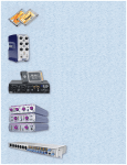
3. FUNCTIONAL DESCRIPTION
Two subassemblies comprise the AL2273 system. The signal handling interface modules are housed in a double high circuit card chassis that is usually mounted at the rear of a 19”-RETMA electronic equipment rack. Up to 16 Input modules are installed in the top half of the chassis and 16 Output modules are installed in the bottom half of the chassis. Each module supports 16 signal paths, input or output. In most circumstances, each signal path is supported by a separate connector such as the BNC type. Control and display are accomplished using the Control Chassis, which is usually mounted on the front of the equipment rack.
Control of signal routing paths is affected by any of two methods: Direct Entry to the front panel Touch-Screen Display,
Remote Control by way of the Ethernet port using Instruction-Line entry using the Native Network ASCII Transfer mode.
Storage and Retrieval of multiple Configuration definitions is provided locally within the Control Chassis as well as through the USB port to a compatible memory device.
A POGEE L ABS, I NC.
1
1.11.07
Tel: 215.699.2060 Fax: 215.699.2061
E-mail: [email protected]
4. SPECIFICATIONS
INPUTS:
Up to 256 Signals (128 Pairs)
16-Inputs Minimum
Scaleable in Groups of 16
Input Over-Voltage Protection
Signal Type
TTL
Custom Switch Designs Available
OUTPUTS:
Up to 256 Signals (128 Pairs)
16-Outputs Minimum
Scaleable in Groups of 16
Short-Circuit Protected
Signal Type
TTL
Custom Switch Designs Available
DATA BANDWIDTH:
TTL 35 Mbps
CONTROL:
Front-Panel
Dual Touch-Screen
Remote Ethernet with ASCII Instructions via Telnet
CONFIGURATION STORAGE /
RETRIEVAL:
Local - 256 Individual Formats
USB Removable Memory
MECHANICAL:
Control Panel
19” Rack Mount
7” High, 15.75” Deep
Switch Chassis
19” Rack Mount
24.5” High, 6” Deep
ETHERNET
REMOTE
CONTROL
PROCESSOR
1
2
15
16
17 - 32
33 - 48
INPUT CARD # 1
INPUT CARD # 1
INPUT CARD # 2
INPUT CARD # 3
241 - 256
INPUT CARD # 16
CONTROL PANEL
GRAPHIC
DISPLAY
BERT
PRN GENERATOR /
RECEIVER
KEY-
PAD
1
2
USB
OUTPUT CARD # 1
NON-BLOCKING
SWITCH
MATRIX
ANY INPUT TO:
ANY
SINGLE
OUTPUT
OR
MULTIPLE
OUTPUTS
15
16
OUTPUT CARD # 2
OUTPUT CARD # 3
17 - 32
33 - 48
OUTPUT CARD # 16
241 - 256
POWER:
100 to 240V AC, 50 to 60 Hz
Dual Redundant Pluggable DC Power Supplies
ENVIRONMENT:
Operating temperature: 0
0
C to +50
° C
Relative Humidity: 0 to 95%, non-condensing
OPTIONS:
I/O Module Type: TTL
Custom Switch Designs Available
1/11/07
Apogee Labs Inc. products are sold by description only. Apogee Labs Inc. reserves the right to make changes in circuit design, software, hardware and/or specifications at any time without notice. Although Apogee Labs Inc. believes that the information provided is current and accurate, Apogee Labs Inc. does not assume any responsibility or liability for the use of any product described. It is the responsibility of the user to determine appropriate use of the product in any given application .
2
advertisement
* Your assessment is very important for improving the workof artificial intelligence, which forms the content of this project
Related manuals
advertisement