advertisement

Instruction Sheet
PA-00298
Sept 2007
W-OLC
Mechanical Oil Level Regulators
Installation & Service Instructions
Theory of Operation:
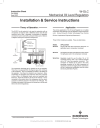
The W-OLC line of controls is to be used in conjunction with an oil separator, oil reservoir with a differential check valve (90 psid maximum) and oil filter. Alternately, a combination oil separator and reservoir can be used with a pressure limiting valve. Below is a diagram showing the component arrangement.
To
Condenser
Filter Drier
Differential
Pressure Valve
Oil Reservoir
Compressor
Discharge
Common Suction
Oil
Separator
OLC Oil Controls
The compressor discharge gas is directed into the oil separator.
There the oil is separated from the frigerant gas which continues to the condenser. The oil is collected and drains to the bottom of the separator. From there it is directed to an oil reservoir. (Note:
Combination oil separators and reservoirs direct the oil directly to the oil filter.) A differential check valve (not available from
Emerson) should be located on the top of the reservoir. This is connected to the suction side of the compressor and the valve’s purpose is to limit the pressure in the reservoir to 10-90 psid. The oil outlet at the bottom of the reservoir is directed to an oil filter and then to the oil level regulator(s).
Application
The primary application of the Oil Level Regulator is on multiple compressor racks although it may be adapted to single compressor units. (Consult Emerson Climate Technologies Flow Controls
Division / Applications Engineering Department.)
Three W-OLC models are available. These are listed below.
MODEL APPLICATION
W-OLC-4 Carlyle) 06D and 06E compressors (Requires 1/4 sight glass level in compressor crankcase)
W-OLC-2 All Copeland and other manufacturers which require
1/2 sight glass level in the compressor crankcase
W-OLC-2-4 Adjustable model for use for either 1/4 or 1/2 crankcase oil level. Note: This model is equipped with a 3/8" male flare equalizer connection. This connection is intended to be piped to the same equalizing connection of the other compressor oil regulators to prevent oil logging of the compressors due to oil entering the compressor from the suction side during extended off-cycles.
www.emersonclimate.com/flowcontrols
11911 Adie Road P.O. Box 411400 St. Louis MO 63141 USA CUSTOMER SERVICE (314) 569 - 4666
page 2
Instruction Sheet
PA-00298
Sept 2007
W-OLC
Mechanical Oil Level Regulators
Installation & Service Instructions
Removal Of Sight Glass
Installation
Figure. 2
GASKET OR "O"-RING
FROM COMPRESSOR
1. It is assumed that safe refrigeration service procedures will be followed to gain access to and in closing the system. Only trained
& qualified service technicians should install this device.
2. CAUTION - The system must be de-pressurized before attempting any work.
FAILURE TO DO SO MAY RESULT IN BODILY INJURY
3. Lower the oil level in crankcase by pumping or siphoning excess oil so that oil level is no longer visible through sight glass.
4. Protect hands and face from contacting the oil which may contain harmful acids.
5. Remove sight glass from compressor. Remove the gasket or
"O"-ring and all other parts. NOTE - Some sight glass housings are pipe thread and have no gasket.
"O"-RINGS
Assembly Of Flanged Adaper Kit To Compressor Figure 3
1. Assemble adapter to compressor using gasket or "O"-ring, bolts and washers which originally held the sight glass to the compressor.
Tighten to approximately five to ten foot pounds. A light coat of oil on the "O"-rings will aid in sealing.
Figure. 3
GASKET OR "O"-RING
FROM COMPRESSOR
BOLTS FROM
COMPRESSOR
Assembly Of Oil Level Regulator W-OLC-2, W-OLC-4, W-OLC-2-4
1. Insert the "O"-ring in the goove of the Oil Regulator flange which which is to be attached to the compressor. Assemble Oil Level
Regulator to compressor using bolts, which originally held sight glass flange to the compressor. Tighten to approximately five foot pounds.
2. Insert the other "O"-ring in the groove on the sight glass. Assemble sight glass flange to the oil level regulator with the nuts and bolts provided. Tighten to approximately five foot pounds. See Final
Connections below.
"O"-RINGS
Figure. 1
"O"-RING
"O"-RING
SIGHT GLASS
FROM COMPRESSOR
Assembly Of Oil Level Regulator
With Threaded & Flanged Adapter Kits
Assembly Of Threaded Adapter Kit To Compressor Figure 2.
1. After removing the plug or sight glass on the compressor, screw adapter into compressor using original gasket or "O"-ring. Thread sealant may be used on threaded joints.
Assembly Of Oil Level Regulator To Adapter Kits Figures 2 & 3
1. Insert the "O"-ring in the groove of the Oil Level Regulator flange which is to be attached to the adapter. Assemble Oil Level Regulator to adapter flange. Rotate flange ring on adapter so that when installed, the Oil Level Regulator is level and in the vertical position only. Use bolts and nuts provided. Tighten to approximately five foot pounds.
2. Insert the "O"-ring in the groove of the open flange on the Oil Level
Regulator. Use bolts and nuts provided. Tighten to approximately five foot pounds.
Final Connections
1. The oil supply line from the Oil Reservoir is connected to the top of the Oil Level Regulator. IMPORTANT - Refill the crankcase to proper level. NOTE: Model W-OLC-2-4 has an equalizer connector which may be connected to the crankcases of parallel compressors.
If not used in this application it must be capped.
2. Failure to leak test after installation of Oil Level Regulator could result in loss of refrigerant.
3. NOTE: Model OC-2-4 is adjustable. To adjust, remove adjustment cap on top. Adjust clockwise to decrease level and counter clockwise to increase level. Each turn changes level approximately 0.050 inch.
www.emersonclimate.com/flowcontrols
11911 Adie Road P.O. Box 411400 St. Louis MO 63141 USA CUSTOMER SERVICE (314) 569 - 4666
advertisement
* Your assessment is very important for improving the workof artificial intelligence, which forms the content of this project
Related manuals
advertisement