
advertisement

First Watt model J2
Power JFET Amplifier
Design and Philosophy
Introduction
You may recall that nearly four years ago I introduced the model F3, an amplifier using the Lovoltech JFET power transistors. The F3 remains one of my favorite pieces, a 15 watt single stage / single-ended Class A power amplifier which achieves very low distortion and exceptional subjective quality for such a simple amplifier. Until now, it has been the only power JFET amplifier that you could buy, excepting the efforts of Sony and Yamaha from more than 30 years ago.
The details of the First Watt F3 are found in the owner's manual (and the DIY articles Zen Variations #8 and #9), and the charms of the amplifier's sound can be found in the many reviews.
First Watt is nothing if not a moving target, so:
Meet the New FETs
Not the same as the old FETs. Advances in semiconductor technology have resulted in new Silicon Carbide (SiC) JFET transistors with much greater voltage, current, and power capabilities. How much more? How about 1200 volts, 30 amps, and 273 watts?
Offered by a new company in Missouri, SemiSouth, these parts are designed for fast high power switching in solar power and electric car applications. They achieve that last little bit more energy efficiency from conversion processes, and that justifies a sampling price as high as $60 or so.
Tomorrow's transistors at tomorrow's prices!
Don't worry, I get a volume discount.
Given the manufacturer's intended use, there is a certain irony in making Class A amplifiers with them. Obviously there are plenty of alternatives for power devices if we simply want to make an regular amplifier.
So you have to ask, aside from the novelty such a new unique part, what makes it special for audio? In two words:
Lower Distortion.
These are the lowest distortion big power transistors I have seen. To give you a sense of the of the difference, Fig 1 shows the distortion between two different transistors operated under identical conditions in a First Watt F2 amplifier:
Here we see the popular IRFP240 N channel Mosfet (top curve) versus a
SemiSouth SJEP120R125 N channel JFET, both operated in Common Source mode, biased at 10 Volts DC and 2 amps by a constant current source and driving an 8 ohm load without feedback.
Zowie! The JFET is about 20 dB better. At the higher power level in this particular circuit, you will see that the difference declines, but that is simply the effect of the triode-like character of the JFET at lower voltages across the device – you can take care of that with a couple extra volts on the supply.
And with a 1200 volt rating you have some margin to burn, in fact you could stick this in where a 300B used to go. Not that I would do such a thing....
Also, the distortion remains much lower at high frequencies as well. This part has about half the input capacitance and about 2/3 the reverse capacitance of the
IRFP240 and the value is more linear, so in typical amplifiers we see about a quarter of the distortion due to junction capacitances.
If we have a gain device that behaves a bit like a tube, then it is natural to try it out in a popular tube amplifier topology. For many aficionados that would be singleended Class A. 300B’s, 211’s and their cousins are often operated single-ended and coupled to an output transformer and regarded by many as the low power musical standard. Single-Ended Class A tube amplifiers are not very powerful, and their measurements are nothing to write home to mom about, but there is no
denying that they have strong musical appeal to a sizable segment of the audiophile population.
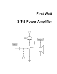
Here is the simplified schematic of the J2. The topology bears a resemblance to the Aleph J, but is not quite the same.
The most important topological difference is that the output stage current source is no longer an “Aleph” current source, but a version of the classic “Mu Follower”.
This approach was chosen because the JFETs can take better advantage of distortion cancellation than Mosfets, but won't do so if the current source is tightly regulated. This has a little less precision, but lower distortion.
The input stage uses parallel Toshiba 2SK170 and 2SJ109 JFETs for both the current source and the differential input (the parallels are shown as single in the drawing). The J2 is a nice blend of parts that are not yet available and parts that are no longer available.
Being a single-ended Class A circuit, its characteristic is “second harmonic”, and at 0.02% at 1 watt, it has about half the distortion seen in an Aleph J. Just as important, it is achieved with a simpler circuit and half as much feedback.
An objectivist might say, “I've got a Carver that measures better than that.”
Maybe, but here's the deal:
There's a certain amount of “zero-sum game” involved. You can have lower distortion, but you have to trade off for it. Maybe you need a more complicated circuit, maybe you need more negative feedback, or both.
A subjectivist viewpoint might be that distortion numbers don't matter anyway.
Probably this is true, but only up to a point. Somewhere above 1%, distortion gets pretty tiresome. That amplifier may find itself in the closet next to the one with .
0000001% – it doesn't sound that good over the long haul.
Complexity and feedback come with their own baggage, and it's a fact that many audiophiles will spend more money on amplifiers with higher distortion. Why is that? My own opinion is that our ears seem to be able to discern something about the process of amplification.
Perhaps amplifier that works hard to remove errors sounds different than one that doesn't have to. The more simple and linear amplifier sounds more relaxed, and it makes me more relaxed when I listen to it. Maybe I'll even fall asleep....
Where was I? Oh, I remember-
Maybe you just need gain devices that distort less in the first place.
These new parts give us more leverage when we are making the trade-offs between low and high distortion, simplicity and complexity, feedback and no feedback. With the proper choices, this makes for better amplifiers.
Better sounding amplifiers.
Read the brochure if you don't believe me:
“The J2 has a sound which is warm and relaxed, combining precision and detail without sterility. With a pair of sensibly efficient loudspeakers, it will give you a toe-tapping experience that other solid state amplifiers do not.”
Now everybody trying to sell you an amplifier will say something like that.
Fortunately, if you are reading this owner's manual, you've already bought the product.
So Congratulations. You made a great choice.
Now I'm going to show you some stuff that is perhaps not already apparent:
Here's the distortion into 8 ohms at 1 Khz from 0.1 watts to 30 watts
Here's the distortion into 4 ohms at 1 Khz
Here's the distortion into 8 ohms at 1 watt from 20 to 20 Khz
Here's what that second-harmonic distortion looks like
Here's the frequency response from 10 to 100 Khz
Here's the square wave at 20 KHz
Setup
The initial setup of the amplifier is very straight-forward. Place the amplifier in a well-ventilated location, as it draws nearly 200 watts during operation and requires as much opportunity to cool itself as possible. You should be able to put your hands on the heat sink during operation. If you can't do this for 5 seconds or so, they need more ventilation.
On the front panel there are two blue LED lights, one for each channel, indicating regulated power to the channel. If the light is on, the power supply for that channel is delivering voltage. On the rear panel you will find pairs of RCA inputs,
XLR balanced inputs, speaker outputs, a fuse holder, an AC power receptacle, and on/off switch and a label.
If you are using the single-ended RCA inputs, make sure that the jumper is present between pins 1 and 3 of the balanced XLR connector, or you won’t get any gain. If you lose the jumper, contact First Watt and I will send you a pair.
The XLR balanced input has pin 1 = ground, pin 2 = (+), and pin 3 = (-).
The label will indicate a serial number and also what AC line voltage the amplifier is set for. If the voltage is 120 VAC, then the fuse value will be a 3AG slow blow fuse rated at 2.5 amps. If the voltage is 240 VAC, then the fuse will be rated at
1.25 amps. Do not substitute a larger value fuse. Contact First Watt if you have any questions.
I'm assuming that you know how to attach the speaker cables to the 5 way output connectors provided. I recommend that you make all the connections with the amplifier power switch in the OFF position, but you will not damage the amplifier circuit by accidentally shorting the output or overdriving the input - my concern is more for the safety of any fragile loudspeaker driver you might be using.
With everything connected up and the source equipment powered up first, you can proceed to turn on the power switch to the amplifier. Turn-on and turn-off thumps and noise are small in this amplifier, and should not present any hazard to delicate drivers. It takes about 1 minute for the regulators to come up to full voltage, so don’t expect full output power for that time.
At this point you should be able to listen to music.
The power supply of the amplifier is isolated from the chassis and AC earth ground by a thermistor which connects the circuit ground to the chassis and earth ground. This helps to prevent ground loops, but the thermistor stands by to conduct AC line voltage to ground until the fuse blows in case of transformer or other such failure.
The input impedance is 100 Kohms, and the input capacitance is very low, so you will find it easy to drive it with single-ended tube equipment if you like.
The J2 has enough damping factor at 20 to work well with loudspeakers that mate well with tube amplifiers in general, and it delivers good performance into 4 ohms also – see the distortion curves at the back of this manual. It is designed around relatively high efficiency speakers and it particularly shines with those that have 90 dB/watt sensitivity or greater, but you can hook it up to anything you like, as long as you adjust your expectations as to how loud it will play.
The amplifier requires about 1 hour of operation to reach normal operating temperature, and this warm-up time is appropriate for the most critical listening, but is not otherwise an issue. The amplifier’s final adjustments were been made after an hour, but the performance difference between 1 minute and 60 minutes is not very great.
I do not personally see a reason to run the amplifier all the time, but you can do that if you want to. The power supply capacitors are likely to last about 15 years or so, and while they will slowly dry out just sitting there, they will have a shorter life span with the amplifier running constantly. Also, at 200 watts it makes economic sense to shut the amplifier off if you aren’t planning on using it for the rest of the day.
Again, the heat sinks on this amplifier run fairly hot, and you want to make sure that they get adequate ventilation. They will run at around 25 degrees C. above the ambient temperature, which puts them around 50 degrees in the average listening room. At this temperature you should be able to put your hand on them for about 5 to 10 seconds or so.
If you have any questions, contact First Watt. I answer all questions, even if the
answer is no.
www.Firstwatt.com
Now the following is for your protection –
Do not defeat the AC line Earth ground connection on the amplifier power cord. It provides an extra barrier to prevent potential shock hazard.
Do not replace the fuse with a type other than specified.
Do not operate the amplifier outside in the weather, or in and around water or anything resembling water. If you spill a drink in the amplifier or if your dog/cat/child urinates on it, turn it off immediately, unplug it, and do not operate it until cleaned by a qualified technician.
If something gets loose or rattles around inside or smells funny, or if you can’t touch the heat sinks for 5 seconds or so, then turn it off, unplug it from the wall, and contact First Watt.
There are no user serviceable parts inside. Do not open the amplifier, and if you do anyway, don’t operate it with the cover off. There are hazardous voltages inside. If you need to change the operating AC voltage, contact First Watt.
Once Again:
If you have a problem, contact First Watt. We are much happier helping you solve problems so that we can be certain that it’s done properly. If you are far away and don’t want to ship the product for repair, we will assist your technician with information and parts.
www.Firstwatt.com
Summary of the nominal specifications:
Measured at 120 V AC and an 8 ohm load:
Distortion @ 1 watt .025% @ 1 KHz,
Input Impedance 100 Kohm
Balanced input CMRR
Gain
Input Sensitivity
Damping Factor
Output power 8 ohms
Output Power 4 ohms
Frequency response
Noise
Power consumption
Fuse
-60 dB @ 1 Khz
20 dB
280 mV = 1 watt, 1.4 V = rated power
20
30 watts @ 1% THD, 1KHz
15 watts @ 1% THD, 1 KHz
- 1 dB @ 4 Hz, 100 KHz
100 uV unweighted, 20-20 KHz
200 watts
3AG slow blow type -
2.5 Amp for 120VAC
1.25 Amp for 240 VAC
Warranty: Parts and labor for 3 years, not covering shipping costs or consequential damages.
Copyright 2009 General Amplifier
General Amplifier Inc.
PO BOX 7607
RENO NV 89510-7607 www.Firstwatt.com
advertisement
* Your assessment is very important for improving the workof artificial intelligence, which forms the content of this project
Related manuals
advertisement