advertisement

JKBA-1 / EASY SETUP
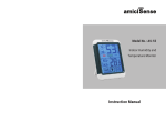
Extremely user friendly weather station with barometer and trend indicator, indoor thermo-hygrometer, wireless outdoor thermometer with frost protection, radio controlled clock
Table of contents
1. Introduction...............................................................................................................
42
2. Operating elements..................................................................................................
43
2.1 LCD (display) and buttons front side..................................................................
43
2.2 Stand, battery compartment and button on back side........................................
44
2.3 Remote sensor (Temperature)...........................................................................
45
3. Set-up.......................................................................................................................
46
4. Extended operation..................................................................................................
46
4.1 Weather forecasts..............................................................................................
46
4.2 Air pressure indicator..........................................................................................
46
4.3 Trend indicator....................................................................................................
47
4.4 Temperature / Moisture......................................................................................
48
4.5 Time function......................................................................................................
49
5. Troubleshooting........................................................................................................
50
6. Battery Change........................................................................................................
51
7. Care of the device....................................................................................................
51
8. Support.....................................................................................................................
51
9. Functions and technical data....................................................................................
52
40
KSPO:1215-10
IROX OST21&TS01-MANUAL 4(Eng)
SIZE:W160 x H170(mm)
BY Lai HZ 17/11/10
1. INTRODUCTION
Meteocentrale.ch and unwetterzentrale.de are weather forecasting portals operated by Meteomedia AG.
Meteomedia is one of the leading weather services in Europe and operates Severe Weather Centres in Switzerland, Germany, and France which makes them the specialists for modern early storm detection.
The core of the company is our extremely extensive weather station measurement network. It is one of Europe’s largest measurement networks. Local and reliable forecasts are made using this measurement network.
Thanks to the collaboration with Meteomedia, Irox, market leader in the manufacturing of measuring devices, has created a product line that convinces with high quality measurements, easy handling, and elegant design.
JKBA-1 is a high quality barometer with thermo/hygrometer that provides you with absolutely new trend indications for weather development.
Setting-up and using this device is very easy. Please read chapters 2 and 3.
The other chapters explain a few details that might be helpful to you, for example if the radio controlled clock does not receive a signal and/or you do not live within the central European time zone.
In the original package you will find following parts:
• The main unit (the receiver)
• A table stand
• A wireless external sensor (transmitter)
• This Instruction Manual
42
41
2. OPERATING ELEMENTS
2.1 LCD (display) and buttons front side
All functions can be read from the liquid crystal display (LCD) in 3 windows.
D
A
B
I
C
E
F
G
H
A. CLOCK
B. TEMPERATURE / MOISTURE
C. WEATHER / AIR PRESSURE
D. °C/°F button
Changes the temperature unit (°Celsius or °Fahrenheit)
E. MEM / RESET button
• MEM: Press briefly to display min/max recorded saved values of the thermometer and hygrometer.
• RESET : Press and hold for 3 seconds to delete saved values.
F. CHART/SYNC button
• CHART: Press repeatedly to change graphic display of pressure history from
- stacking bar charts increasing from left (-24 Hr) to right (0 Hr)
- stacking bar chart silent indicator with blinking column "0 Hr"
- line diagram silent with blinking segment "0 Hr"
"Hr" stands for “hours” and the chart displays the pressure history over the last 24 hours. "0 Hr" is the latest current state.
• SYNC : Press and hold for 3 seconds to start synchronization with the sensor last logged into the device. Caution: After changing the
sensor battery or to log-in a new sensor you must press this button again for 3 seconds while the waves above are blinking!
G. SET TIME button
• SET TIME : Press and hold for 3 seconds to move to time setting mode. Please also read the chapter on “Time Setting”!
H. button
I . button
• When setting time and height these buttons can be used to adjust the value ( or ), increase ( ) or decrease ( ). To quickly change a
value in the setting press and hold the or button.
43
2.2 Stand, battery compartment and button on back side
J
K
L
M
J. PRESSURE UNIT / SET ALTITUDE button
• PRESSURE UNIT: Press briefly: Changes the pressure unit (hPa or inHG)
• SET ALTITUDE : Press and hold for 3 seconds to move to setting for local height above sea level. Then set with +/- button.
Important: Exit setting by briefly pressing the button. This leads to a reset and new start of the forecast calculation!
K. WALL MOUNT
• Prefabricated opening to, using a screw or nail, hang the device on the wall.
L. BATTERY COMPARTMENT
• Is designed for 4 tubular batteries, size AAA. Please observe polarity when inserting batteries.
M. TABLE STAND
• This stand can be clicked into the bottom of the device for positioning on a table.
2.3 Remote sensor (Temperature)
In an open and undisturbed field the measuring values can be transmitted over a distance of up to 30 meters (100 feet). The remote sensor is weatherproof and can be used both outdoors and indoors.
A. BATTERY COMPARTMENT: Designed for two AAA batteries
B. WALL MOUNTING: For mounting outdoors use the wall bracket.
44 45
3. SET-UP
Setting-up the JKBA-1 is very easy. Just follow the steps below.
1- Activate the batteries in the remote sensor
2- Position the remote sensor in the same room in a radius of about 1 meter to the display unit.
3- Activate the batteries in the display unit: First a full segment display will appear on the LCD for about 3 seconds.
4- Then the sea level setting (0m) will blink on the display. You now have 8 seconds to begin setting your local sea level using the +/-
buttons. When you have reached the desired height wait 8 seconds, then the device will start receiving data from the remote sensor and
then the time from the time signal transmitter DCF77. Wait until all data (time and temperature) are indicated correctly on the device.
That is all you have to do! From now on your device will function without you ever having to push another button.
In chapter 4 you will find details for optional settings and also information on certain procedures.
4. EXTENDED OPERATION
All operations on the device are carried out by pressing buttons. It is very important that you read chapters 2 and 3!
In these chapters you will find additional information about the functions
4.1 Weather forecasts
This Irox device uses a high quality pressure sensor to measure barometric pressure and the respective changes. This information is then, using a by meteorologists specially developed algorithm, used to calculate a weather forecast for the coming 12-24 hrs. Eight different forecasts are possible:
Sunny Slightly cloudy
Cloudy Rain Heavy rain
Snow Heavy snowfall
Thunderstorms
/Stormy
COMMENT: These calculated weather forecasts have a reliability of approx. 70%. The forecast is displayed, not the current weather. SUNNY means clear weather day and night.
4.2 Air pressure indicator
The indication of the air pressure depends on the setting of the sea level.
If the setting is 0 meters, you will see the local measured pressure. This value is based on the factory calibration of the pressure sensor.
If you have programmed the height above sea level of your location you will see the barometric pressure measured at your location, calculated from the local pressure measured and the set height above sea level. With this value you can meteorologically position your location with other available information (e.g. the isobar map on TV, Internet or in your daily newspaper).
With the height adjustment setting you can also adjust any slight deviations to a precision measuring instrument and so to say calibrate the pressure sensor. As a rule: 5m more in height, pressure reading is increased by 1 hPa.
4.3 Trend indicator
You have a total of 4 different trend indicators available, 2 of them simultaneously:
1- The large Weather Icon on the upper right of the display shows the forecast for the next 12-24 hrs. On the left side of that, underneath the pressure indicator, you will see a smaller icon with 3 arrows. The small icon indicates the forecast 12 hours before, thus giving you additional information regarding the forecast development.
2- Graphic pressure history
- One bar equals 1 hPa. This displays the pressure history of the past 24 hours.
- If you change the pressure units (from hPA to inHG), the graph will remain the same. The only thing that vanishes is the scaling on the
right side of the graph with the -4 to +4 hPa.
- The graph can be displayed in 3 different ways:
Dynamic stacking bars, increasing from -24 hrs. to 0 hrs.
Static stacking bars, only the 0 hrs bar blinks
Static line diagram, only the segment 0 hrs blinks
46 47
4.4 Temperature / Moisture
The display unit measures the temperature and relative humidity and receives additional measurements from the remote sensors included in the delivery. The temperature can be displayed in °C or °F.
The comfort zone is calculated from the thermo/hygro measurements of the display unit.
A frost warning is programmed on the remote sensor. When the temperature measured by the remote sensor drops below 3°C, the frost warning icon will appear on the display.
SEARCH FOR REMOTE SENSOR
You can start the search for the remote sensor manually by pressing and holding the SYNC button for 3 seconds. The wave icon will start to blink.
The wave icon indicates the receiving status of the remote sensor signal:
Icon Status
Searching for the remote sensor signal
Sensor signal successfully received
No signal received for over an hour
With this search procedure the device searches the same sensor that was already previously logged in. If you replace the batteries in the sensor, the sensor gives itself a new code and will then no longer be recognized by the display unit. You can resolve this problem by:
- removing the batteries from the display unit and replacing them with new ones
or
- if the batteries are still O.K., repeating the logging in procedure as described above by pressing and holding the SYNC button and while
the wave icon is blinking press and hold the SYNC button again for 3 seconds. The temperature indicator will start to blink indicating
that a new sensor is being searched for and will be logged in.
INDICATION AND CONDITIONS OF THE COMFORT ZONE
The COMFORT ZONE is indicated for the room where the main device is positioned. The COMFORT ZONE is a function regarding temperature and rel. humidity. There are 5 conditions COMFORT, WET, DRY, HOT and COLD.
48
4.5 Time function
The time signal DCF 77 is transmitted by the atomic clock in Mainflingen near Frankfurt/Main. The long-wave transmitter has a range of up to 1500km.
If the time icon is displayed without waves you have reception problems. Please observe following points:
- There are fewer disturbances in the atmosphere during the night which increases the likeliness of reception. One reception per day is
completely sufficient to ensure the preciseness of the clock by +/- 1 second
- Make sure that the device is at least 2 meters (8 feet) away from possible sources of disturbance such as TV, computer, monitor,
microwave etc.
- In rooms with concrete or metal walls (e.g. cellar rooms, modern office buildings etc.) the receipt of the signal may be more difficult due
to the shielding. In such cases find a better location for the device near a window. Sometimes it also helps to simply turn the device by 90°,
thereby improving the alignment of the receiving antenna.
Caution: During the setting procedure as described below you will exit the setting mode if more than 1 minute passes between pressing the buttons. The settings already made up to this point will then be deleted. To prevent this from happening each setting must be completed.
RADIO CONTROLLED CLOCK RECEIVING LOGIC
1. As described in chapter 3 the time transmitted by the time signal transmitter DCF77 is automatically received when the batteries are
activated. The time signal reception takes about 3-10 minutes. During receiving the icon will blink, if reception is good with waves if
reception is poor without.
2. If you would like to switch the automatic time reception off and then on again you can do so with the “setting”.
3. During normal operation an automatic time reception will be activated daily at 0:00, 3:00, 6:00 and 12:00.
4. As soon as the device has received a signal the time will be correctly adjusted and the icon is active.
5. If reception is poor the icon will be displayed. You may then set the clock manually at any time. The next reception attempt will then be
activated during the night.
SETTING
You can choose between two operating modes for the clock:
1- Radio controlled clock with regular time comparisons. In between the active receptions the time runs on integrated quartz (this is a
factory setting which is reactivated after every battery replacement)
2- Strictly as a quartz clock
Move to set mode with the SET TIME button (press and hold for 3 seconds). “On” will appear in the time display. This means the radio receiving is activated.
With the +/- buttons you can make changes to the setting, with the SET TIME button you move to the next setting.
The setting options vary depending on operating mode "On" or OFF"
Operating mode 1 – Radio controlled clock on = On
- Time indication format: 24 hours or 12 hours resp. AM/PM
- Time zone setting (standard =0, adjustable from -9 to +9 hours):
Time deviation as compared with the received radio time as the respectively valid time in Central Europe (Germany, France, Switzerland,
Denmark etc.). If you set a time zone “ZONE” and the accordingly corrected time will appear on the time display. This is ideal for
locations where the DCF77 time signal is received but that have a different time such as Great Britain (-1HR) or Finland (+1HR)
Complete the setting with the SET TIME button
Operating mode 2 – Radio controlled clock off = OFF
- Time indication format: 24 hours or 12 hours resp. AM/PM
- Setting the hours
- Setting the minutes
We recommend this operating mode for locations where the time signal can not be received. Switching off the receiver spares the batteries.
49
5. TROUBLESHOOTING
If you notice a malfunction of your device, always first check the battery please. Always replace the batteries in the display unit and in the remote sensor!
Also please check the following before contacting the customer service of the store where you purchased the device:
Issue
Display unit
Symptom
Radio controlled clock does not receive signal
Solution
Reposition the device. Preferably near a window and leave it there overnight.
Perhaps an additional turning of the device by 90° would help.
Display unit/
Remote sensor
Remote sensor is not being received
Replace batteries (in both devices!)
Check the position of the sensor. Read the details explained below.
Start sensor search with the SYNC button (press and hold for 3 seconds).
If this is not successful repeat and while the waves above OUT are blinking press and hold SYNC button for 3 seconds again!
Information regarding transmittal from remote sensor to display unit
• It is very important that you activate the batteries in the remote sensor BEFORE activating the batteries in the display unit. As soon as the
batteries are inserted in the remote sensor it will begin sending thermo measurement data. The display unit will start receiving data as soon
as its batteries are activated.
• Before mounting the sensor at its final position we strongly recommend ensuring the successful communication, which means checking the
data on the display unit. To do so place the sensor within a radius of approx. one meter of the display unit. Make sure there are no sources
of disturbance in the vicinity of the two devices.
• As soon as the measurement data appears on the display unit you may mount the sensor within the maximum distance of 30m at a position
of your choice.
REMARK:
• Before operating the device wait until data from the sensor appears on the display unit!
• The effective receiving radius may be limited by building structures (e.g. reinforced concrete walls), metal surfaces or grates, electronic
devices as well as the position of the sensor and/or the receiver.
Placement of the sensor and the display unit
• Place the sensor so that the back or front side is facing the receiver. If possible avoid shields or disturbances in the line of transmission.
• The remote sensor is weatherproof. Avoid direct sunlight, rain, or snow. Preferable are measuring points in the shade, for example under a
weather protected roof with good air circulation.
• The remote sensor can be stood or mounted vertically on a wall. To do so please use the provided wall bracket, this should be mounted on
the wall with a screw not with a nail.
• Ideally the sensor should be placed 1.25m (4 feet) over the ground respectively grass surface. Stone, asphalt, or tar surfaces can become
extremely warm and thus falsify the measurement.
• Heat sources such as a fireplace or heaters of any type must be avoided.
• The display unit must be positioned within the transmitting radius of the sensor and away from the direct influence of heating or cooling
apparatus. A distance of at least 1 meter must also be maintained between sensor and display unit and other remote equipment. Remote
equipment is, for example, cordless telephones, wireless headphones, baby monitors, mobile phones etc.
6. BATTERY CHANGE
: BATTERY CHANGE INDICATOR
The batteries last for about 8-12 months. Depending on the batteries used this time frame may be a bit shorter or longer. A battery icon will appear, to prevent an undesired and unexpected interruption of operation.
- Battery icon in the temperature window
This means that the batteries in the remote sensor need to be replaced
- Battery icon in the clock window
This means that the batteries in the display unit are becoming too weak and must be replaced.
Important:
Use only new batteries and never combine old batteries with new batteries. Observe polarity when inserting batteries!
Please also remember that used batteries do not belong in domestic trash, they should be disposed of at designated collection points.
Our environment will appreciate it!
Important note on batteries
• The JKBA-1 is delivered with batteries so that you can immediately put it into operation. These batteries may not last as long as store
bought batteries. As soon as you have to replace the batteries in the remote sensor we recommend using alkaline batteries. Especially when
outdoor temperatures drop to 0°C (32°F) or below these batteries will ensure a more reliable transmittal. If possible even use lithium
batteries.
• Never use rechargeable batteries. The output of rechargeable batteries is often not sufficient for our devices.
7. CARE OF THE DEVICE
- Do not expose the device to extreme temperatures or direct sunlight over longer periods.
- Avoid blows and shocks of any kind to the device.
- For cleaning use a dry soft cloth that you have moistened with water and a very mild cleaning agent. Never use volatile substances such as
benzene, thinner, cleansing agents in spray cans etc.
- When the device is not being used store it in a dry area and out of the reach of small children. In such cases it is important to remove the
batteries!
- If the device is activated under extreme coldness it may occur that the display becomes illegible. As soon as it is returned to a warm
environment the device will function normally again.
- Please keep the Instruction Manual and other documents delivered with the device stored carefully so that you can reference them at a later
point if necessary.
- Important: All disposal fees in Switzerland (vRG) as well as in the EU (WEEE) for all Irox devices are covered.
8. SUPPORT
This device is a new development of Irox Development Technology. All information was made and checked by means of a functioning device. It may occur that adjustments and improvements of the device will take place that due to typographical procedures were not able to be listed in this manual. Should you notice deviations which make it difficult for you to operate and use of the device you may at any time download the latest manual onto your PC free of charge at www.irox.com.
50 51
9. FUNCTIONS AND TECHNICAL DATA
Display unit
Time
• Absolutely accurate time by receiving the time signal DCF77 from Frankfurt.
• Time format adjustable (12 or 24 hour format)
• Time settings manually or as deviation from DCF77 time
Weather/Climate
• Weather forecast for coming 12 to 24 hours via 8 icons. Plus additional trend indicator.
• Room temperature and relative humidity with min/max storage and 5 level Comfort Zone.
• Outdoor temperature via wireless remote sensor with frost warning.
• Barometric pressure display in hPA or inHG
• Setting of sea level to calculate pressure at sea level
• 24 hour record of pressure development with graphic display (choice of three graphic formats)
Measuring data
Temperature
Measurement range: -5°C to +50°C (23.0°F to 122.0°F), Resolution: 0.1°C / 0.2°F
Relative Humidity
Measurement range: 30% to 80%, Measurement cycle: 10 seconds
Barometer
Measurement range: 750 to 1100m hPa at 25°C (22.15 to 32.49inHG)
Measurement cycle: 20 minutes, Height adjustment range: -200m to +3500 m
Power Supply
4 x AAA batteries (1.5V)
Dimensions
139 x 107 x 15 mm plus table foot
Remote sensor
• Measuring and transmittal of outdoor temperature via 433mHz
Measuring data
Temperature
Measurement range with alkaline batteries: -10°C to + 60°C (14°F to + 140°F)
Resolution: 0.1°C/ 0.2°F
Rel. Humidity
Measurement range: 30% to 80%, Measurement cycle: 10 seconds
Radio frequency: 433 MHz, Transmission distance: Max. 30 meter (100 feet)
Transmitting interval: approx. 45 seconds
Power Supply
2 x AAA 1.5V batteries
Dimensions
38 x 105 x 18 mm plus mount
© Irox Development Technology
52
advertisement
* Your assessment is very important for improving the workof artificial intelligence, which forms the content of this project
Related manuals
advertisement