advertisement

XPress™ Ethernet Bridge Multipoint: User
Guide
Overview
The XPress Ethernet Bridge (XEB) replaces costly wiring with a solution that can enable industrial
Ethernet PLCs, electronic (LED) signs, remote Wi-Fi APs, Pan/Tilt/Zoom security cameras, VoIP phones, Internet kiosks and more. With a range of up to 15 miles (line-of-sight with a high gain antenna) and the ability to transmit through as many as 10 standard walls, the XEB uses the added range and capabilities of the 900 MHz band to communicate where Wi-Fi and other wireless data products fall short.
Contents
• 1 XEB RF Modem: XEB09-BCS = Commercial (Indoor), XEB09-BIS = Industrial (Outdoor)
Accessories Kit also includes:
• 1 Half-wave, 2.5 dBi dipole antenna
• 1 6VDC/110VAC power adapter (Commercial only)
• 1 12VDC/110VAC power adapter (Industrial only)
• 1 Power over Ethernet injector (Industrial only)
• 1 XEB Multipoint manual
How It Works
The XEB radios allow you to create a long range, wireless Ethernet network for up to 16 Subscriber
Units (SU) per Access Point (AP). The AP automatically scans for the best of the 12 available radio channels. Then it encrypts Ethernet data received from the network and transmits it wirelessly to the correct SU. The AP is constantly monitoring the network performance and automatically changes channels if the performance is hindered because of interference.
Select any of the 12 radio channels by toggling DIP switch settings. (See DIP Settings for additional information.) It is possible to operate up to 12 APs in the same area with each AP on a different channel. To avoid interference, space the APs at least 10 feet apart. Typically, the AP is attached to the wired network via an Ethernet Cable. The Auto MDI/MDIX feature on each XEB will work with either a straight through or crossover network cable.
Note: The AP does not have a MAC/IP address.
Any 10BaseT Ethernet Client Device (ECD) can be connected to an XEB SU. Each SU encrypts Ethernet traffic received from the attached ECD and transmits the data wirelessly to its AP. You can plug each
SU directly into an ECD without need for any drivers or loading software on the ECD. Crossover cables are never needed.
You can only attach one ECD to each SU. The DIP switches on the SU should be in the default OFF setting. To avoid overloading the radio’s receiver, place the SU at least 10 feet from the AP. 100-foot spacing is recommended if using high-gain antennas.
Note: The SU does not have its own MAC/IP address.
1
2
4
8
16
32
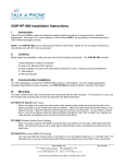
Name
Power
RFTX
RFRX
Eth Link
XEB radios use electronic network keys that allow you to group radios together to form a network.
Network keys are shared between radios by connecting an Ethernet Cable between the RJ45 ports while the radios are in “key exchange mode” (radios that are in “key exchange mode” display the 6
LINK QUALITY LEDs blinking sequentially back and forth).
Creating the Network
To share the keys and to create the network, follow these steps:
1. Select which radio will be the AP by setting DIP switch 1 ON.
• The other radios will function as SUs and do not require any DIP settings.
2. Connect an Ethernet Cable from the AP to each SU to transfer the network keys.
• For the Industrial/Outdoor XEB, the key exchange will occur through an Ethernet cable attached to the supplied POE injector. Key exchange will not work through a switch or hub.
Once the key sharing is complete, the AP and SU change their LED displays in confirmation of the successful programming:
The SU blinks one of the GREEN LINK QUALITY LEDS.
The AP illuminates the LED labeled RF RX, and the AP remains in “key exchange mode.”
You can add additional SUs to the network or reprogram an SU to join a different network. Likewise, an SU can be changed into an AP and an AP into an SU. If DIP 1 is accidentally toggled, it can be turned back, and the radio still retains all the network associations it had in its previous mode
(assuming that the radio had not yet successfully key exchanged with a new network). You can reset an AP by programming it as an SU and then turning it back into an AP again.
SUs that have not yet received a network key boot up in “key exchange mode” and wait to receive a key. SUs that have received a network key will boot-up for 5 seconds in “key exchange mode” and will look to see if a new AP is present. If a new AP is present, then the SU exchanges keys with the AP; otherwise, the SU begins normal operation after the 5 seconds.
APs that have not yet issued network keys boot up in “key exchange mode” until they have issued network keys to at least 1 SU. Once the AP has issued keys, it will only boot-up for 5 seconds in “key exchange mode.” If an SU is present during the 5 seconds, then the AP will issue new keys to the SU and will then remain in “key exchange mode” waiting for more SUs to be attached. Once all new SUs have been attached, the AP must be power cycled. The AP will boot-up and after 5 seconds of “key exchange mode,” it will enter normal operation.
LED Display
Function
Unit has power and has successfully booted.
Radio transmission is occurring.
Radio reception is occurring.
The Ethernet Port has a valid
Ethernet connection.
By adding the numbers that are lit the user can determine the current radio channel.
1 903.12500 MHz
2 905.20833 MHz
3 907.29167 MHz
4 909.37500 MHz
5 911.45833 MHz
6 913.54167 MHz
7 915.62500 MHz
8 917.70833 MHz
9 919.79167 MHz
10 921.87500 MHz
11 923.95833 MHz
Color
Red
Green
Green
Green
Green
2
Name
Link Quality
Meter: The more
LEDs that are lit the higher the link quality. or
"Key exchange mode" when blinking sequentially
Function
12 926.04167 MHz
Excellent link quality
No retransmissions
Very good link quality
Few retransmissions
Good link quality
Occasional retransmissions
Fair link quality
Some retransmissions
Poor link quality
Many retransmissions
No link quality
No link available
Color
Green
Green
Amber
Amber
Red
Red
Initial Setup
Use the following procedure to perform an initial setup:
1. Select the radio that will operate as the AP and set DIP switch 1 ON to enable the AP operation.
2. Plug in the AP:
• The LINK QUALITY LEDs will blink sequentially showing that the radio is hunting for an
SU to share keys with.
3. Plug in an SU:
• The LINK QUALITY LEDs will blink sequentially showing the radio is hunting for an AP to supply a network key.
4. Connect an Ethernet cable from the AP to the SU and the units will automatically exchange keys over the Ethernet cable. (A key exchange will not work through a switch or hub.
Crossover cables are not required.)
• On the AP, the LINK QUALITY LEDs will show that the radio is still in “key exchange mode” and the RF TX LED will be lit showing that the keys exchanged successfully.
Ignore the other LEDs.
• On the SU, the LINK QUALITY LEDs no longer blink sequentially and will show that the radio has stopped hunting and now has a slowly blinking pulse on one of the GREEN
LINK QUALITY LEDs. Ignore the other LEDs.
5. Repeat steps 3 and 4 until all SUs are successfully programmed.
6. Power cycle all radios for the new keys to take effect.
7. Deploy the radios.
Adding New Subscriber Units to the Access Point
Use the following procedure to add new SUs to an AP:
1. Disconnect the AP from the network and disconnect power from the AP.
2. Connect an Ethernet cable from the AP to the SU. (A key exchange will not work through a switch or hub. Crossover cables are not required.)
3. Plug in the new SU then plug in the AP. The units will automatically exchange keys over the
Ethernet cable.
4. Repeat steps 2 and 3 until all SUs are successfully programmed.
5. Power cycle all radios for the new keys to take effect.
6. Reconnect the AP to the Network and deploy the new SUs.
3
To Re-key a Subscriber Unit to a New Access Point
Use the following procedure to re-key an SU to an AP:
1. Select the radio that will operate as the AP and set DIP switch 1 ON to enable Access Point operation.
2. Plug in the new AP.
3. Connect an Ethernet cable from the AP to the SU (key exchange will not work through a switch or hub – crossover cables are not required).
4. Plug in the SU.
5. Repeat steps 3 and 4 until all SUs are successfully programmed.
6. Power cycle all radios for the new keys to take effect.
7. Deploy the radios.
DIP Settings
DIP 1
AP or SU
• By selecting DIP 1 ON, the radio will operate as an AP.
• By selecting DIP 1 OFF, the radio will operate as an SU.
DIP 2
<Manufacturer test mode - no end user functionality>
DIP 3-8
Automatic frequency selection mode (DIP 3-8 OFF for automatic mode):
The XEB radios are designed to automatically select and continuously optimize the performance of their radio channel with frequency agility techniques. The radio channel is monitored to ensure it is providing low error rates necessary for successful data transmission. In the event that the error rate rises, the AP will automatically change to a new channel. The SUs will follow. There are 12 nonoverlapping channels.
Frequency agility is turned on by default. It is recommended because it offers an RF communication channel that is highly resilient to interference. For example, in VOIP and CCTV applications, wideband technologies like Wi-Fi can get slowed or stopped by heavy interference. The XEB, in contrast, has more consistent throughput due to its narrow bandwidth at a higher power output, plus frequency agility to move to an unused section of the frequency band.
Manual frequency selection mode:
The operation of the XEB radios can be restricted to a specific channel within the 902-928 MHz band by setting DIP switches 3-8 on the AP as shown in the table below. The SU responds to the AP’s choice of channel, and its DIP switch has no effect and does not need to be selected.
Channels and Settings
5
6
7
8
9
10
11
12
Channel DIP Setting
1 3 On / 4 Off / 5 Off / 6 Off
2
3
4
3 Off / 4 On / 5 Off / 6 Off
3 On / 4 On / 5 Off / 6 Off
3 Off / 4 Off / 5 On / 6 Off
3 On / 4 Off / 5 On / 6 Off
3 Off / 4 On / 5 On / 6 Off
3 On / 4 On / 5 On / 6 Off
3 Off / 4 Off / 5 Off / 6 On
3 On / 4 Off / 5 Off / 6 On
3 Off / 4 On / 5 Off / 6 On
3 On / 4 On / 5 Off / 6 On
3 Off / 4 Off / 5 On / 6 On
Center Frequency
903.12500 MHz
905.20833 MHz
907.29167 MHz
909.37500 MHz
911.45833 MHz
913.54167 MHz
915.62500 MHz
917.70833 MHz
919.79167 MHz
921.87500 MHz
923.95833 MHz
926.04167 MHz
4
Advanced Operation
Contact Digi Support if your application requires:
• Over 16 SUs per AP for roaming/mobility applications
• Multiple APs that use the same network key for roaming/mobility
• Low packet loss rates when using broadcast or multicast Ethernet packets.
Note: If possible, fixed IP addresses are recommended on your network. This is because broadcast and multicast packets (e.g., DHCP, UDP) are sent once and may experience losses at extended range.
Unicast packets (e.g., HTTP, TCP) are sent using advanced error correction and retransmission techniques to ensure delivery.
Technical Specifications
Characteristic
RF transmission rate
Aggregate Throughput
Output power
Receive sensitivity
Ethernet Interface
Radio channels
Automatic frequency select
Manual frequency select
Status LEDs
Error correction technique
Adjacent-band rejection
Regulator type
Power consumption
Voltage
Specification/Description
1.536 Mbps
935 Kbps
+21dBm
-97dBm at lOe-4 BER
RJ45 10BaseT, Auto MDI/MDIX
12 Non-overlapping
Yes - radio channel automatically selected and adaptively optimized
Yes
Power, RF TX, RF RX, Ethernet Link,
6/Channel and 6/Link Quality
Sub-block error detection and retransmission
SAW receiver filter attenuates cellular and pager interference.
XEB09-BCS uses Linear Regulator and XEB09-
BIS uses Switching Regulator
Transmit: XEB09-BCS 2W XEB09-BIS 1.5W
Receive:XEB09-BCS 1.2W XEB09-BIS 1.0W
XEB09-BCS: 5-7 VDC
XEB09-BIS: 9-48 VDC Power over Ethernet
Temperature range
Current draw
Radio Size
Regulatory Approvals
-40˚C to 70˚C (-40˚F to 158˚F)
XEB09-BCS:
350 mA
XEB09-BIS:
150mA at 9VDC
110mA at 12VDC
32mA at 48VDC
XEB09-BCS: 5.5 in (14.0 cm) x 3.4 in (8.5 cm) x 1.2 in (3.0 cm)
XEB09-BIS: 7.9 in (20.0 cm) x 3.2 in (8.0 cm) x 2.1 in (5.5 cm)
FCC ID (U.S. - Part 15.247) R4N-AW900M, IC
ID (Canada) 5303A-AW900M
5
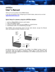
Example Illustration
Commercial (Indoor) radios can communicate with Industrial
(Outdoor) radios.
Figure 1: A typical point-multipoint architecture
Contact Digi
Phone: (801) 765-9885
Online Chat: www.digi.com e-mail: [email protected]
© Digi International Inc., 2007. Digi, Digi International, the Digi logo, and XPress are trademarks or registered trademarks of Digi International, Inc. in the United States and other countries worldwide.
90000888-B
6
advertisement
* Your assessment is very important for improving the workof artificial intelligence, which forms the content of this project