advertisement

www.motor-pump-ventilation.com
M 1 1
8VHUVPDQXDO
www.motor-pump-ventilation.com
Bild 1:
Fig. 1:
Fig. 1:
Fig. 1:
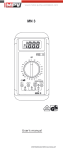
Gerätefrontseite
Front tester panel
Panneau avant de l'appareil
Parte frontal del equipo
Obr.1: Přední strana přístroje
σχήμα 1: Μπροστινή όψη ill. 1: Lato anteriore apparecchio
09/ 2013
Fig. 1:
Rys.1:
Рис. 1.
Voorzijde van het apparaat
Panel przedni przyrządu
Imaginea 1: Partea frontală a aparatului
Fig. 1:
Фронтальная сторона прибора
Framsida
Resim 1: Cihaz önyüzü
0XOWLPHWUH01PSYQRWLFHSGI
09/ 2013 www.motor-pump-ventilation.com
Bild 2:
Fig. 2:
Fig. 2:
Fig. 2: ill. 2:
Fig. 2:
Gleichspannungsmessung
Direct voltage measurement
Mesure de tension continue
Medición de corriente contínua
Obr.2: Měření stejnosměrného napětí
σχήμα 2: μέτρηση DC-τάσης
Misura tensione continua
Meten van gelijkspanning
Rys.2: Pomiar napięcia stałego
Imaginea 2: Măsurarea tensiunii continue
Рис. 2. Измерение напряжения
Fig. 2: постоянного тока
Likspänningsmätning
Resim 2: Doğru Gerilim Ölçümü
Bild 3:
Fig. 3:
Fig. 3:
Fig. 3:
Wechselspannungsmessung
Alternating voltage measurement
Mesure de tension alternative
Medición de tensión alterna
Obr.3: Měření střídavého napětí
σχήμα 3: μέτρηση AC-τάσης ill. 3:
Fig. 3:
Misura tensione alternata
Meten van wisselspanning
Rys.3: Pomiar napięcia przemiennego
Imaginea 3: Măsurarea tensiunii alternative
Рис. 3. Измерение напряжения переменного тока
Fig. 3: Växelspänningsmätning
Resim 3: Alternatif Gerilim Ölçümü
Bild 4:
Fig. 4:
Fig. 4:
Fig. 4:
Gleichstrommessung
DC current measurement
Mesure de currant continu
Medición de corriente continua
Obr.4: ill. 4:
Měření stejnosměrného proudu
Misura corrente continua
σχήμα 4: μέτρηση συνεχούς ρεύματος
Fig. 4:
Rys.4:
Meten van gelijkstroom
Pomiar prądu stałego
Imaginea 4: Măsurarea curentului continuu
Рис. 4.
Fig. 4:
Измерение постоянного тока
Likströmsmätning
Resim 4: Doğru Akım Ölçümü
0XOWLPHWUH01PSYQRWLFHSGI
09/ 2013 www.motor-pump-ventilation.com
Bild 5:
Fig. 5:
Fig. 5:
Fig. 5:
Widerstandsmessung
Resistance measurement
Mesure de résistance
Medición de resistencia
Obr.5: Měření odporu
σχήμα 5: Μέτρηση αντίστασης ill. 5:
Fig. 5:
Misura di resistenza
Weerstandsmeting
Rys.5: Pomiar rezystancji
Imaginea 5: Măsurarea rezistenţei
Рис. 5.
Fig. 5:
Измерение сопротивления
Resistansmätning
Resim 5: Direnç Ölçümü
Bild 6:
Fig. 6:
Fig. 6:
Fig. 6:
Durchgangsprüfung mit Summer
Continuity Testing with buzzer
Contrôle de continuité avec ronfleur
Control de continuidad con vibrador
σχήμα 6: Έλεγχος συνέχειας με ηχητικό σήμα ill. 6: Prova di continuità con cicalino
Zkouška průchodu bzučákem Obr. 6:
Fig. 6:
Rys.6:
Doorgangstest met akoestisch signaal
Sprawdzenie ciągłości obwodu
Imaginea 6: Măsurarea continuităţii cu buzzer
Рис. 6. Проверка целостности цепи (прозвонка)
Fig. 6: Genomgångstest med summer
Resim 6: Sesli Süreklilik Ölçümü
Bild 7:
Fig. 7:
Fig. 7:
Fig. 7:
Diodenprüfung
Diode Testing
Contrôle de diodes
Verificación de diodos
Obr.7: Měření diod
σχήμα 7: Έλεγχος διόδου ill. 7:
Fig. 7:
Prova diodi
Diodecontrole
Rys.7: Pomiar diody
Imaginea 7: Măsurarea diodelor
Рис. 7.
Fig. 7:
Проверка диодов
Diod-test
Resim 7: Diyot Ölçümü
0XOWLPHWUH01PSYQRWLFHSGI
09/ 2013 www.motor-pump-ventilation.com
Bild 8:
Fig. 8:
Fig. 8:
Fig. 8:
Batteriewechsel
Battery replacement
Remplacement de la pile
Cambio de batería
Obr. 8: Výměna baterií
σχήμα 8: Αντικατάσταση μπαταριών ill. 8:
Fig. 8:
Sostituzione batterie
Vervanging van de batterijen
Rys.8: Wymiana baterii
Imaginea 8: Schimbarea bateriei
Рис. 8.
Fig. 8:
Замена батарейки
Batteribyte
Resim 8: Batarya Değişimi
Bild 9:
Fig. 9:
Fig. 9:
Fig. 9:
Aufwicklung der Sicherheits mess leitungen am Gummi-Schutz rahmen
Winding up the safety test leads
Enroulement des câbles de mesure de sécurité sur le cadre de protec tion en caoutchouc
Arrollamiento de las conducciones protegidas de medición en el marco protector de goma
Obr.9:
σχήμα 9: Τυλίξτε τα καλώδια μέτρησης γύρω από το
προστατευτικό κάλυμμα ill. 9:
Navinutí měřících vodičů na pryžový rám přístroje
Fig. 9:
Rys.9:
Avvolgimento dei cavetti di sicurezza intorno al guscio protettivo
Wikkeling van veiligheidsmeetsnoeren
Zwijanie przewodów pomiarowych
Imaginea 9: Înfăşurarea firelor de măsurare pe rama din cauciuc
Рис. 9
Fig. 9:
Намотка измерительного провода
Placering av säkerhetsmätsladdar
Resim 9: Emniyet Ölçüm Tesisatının Lastik çerçeveye
Sarılması
Bild 10: Gummi-Schutzrahmen inkl. frei stehender
Messspitze
Fig. 10: Protective rubber holster with one probe free for single handed opera tion
Fig. 10: Cadre de protection en caoutchouc avec pointe de mesure libre
Fig. 10: Marco protector de goma, con punta de medición libre
Pryžový rám přístroje včetně volných měřících hrotů
σχήμα 10: Προστατευτικό κάλυμμα με ελεύθερο άκρο
μέτρησης ill. 10: Guscio protettivo con puntale di misura libero
Fig .10: Beschermingshoes
Rys.10: Gumowy futerał ochronny z jedną końcówką swobodną do obsługi jednoręcznej
Imaginea 10: Ramă de protecţie din cauciuc
Рис. 10. Установка измерительного провода в клипсу
Fig. 10: Gummiskyddsram
Res.10: Boşta duran ölçüm ucu dahil Lastik koruyucu
çerçeve
0XOWLPHWUH01PSYQRWLFHSGI
www.motor-pump-ventilation.com
Bild 11: Aufstellung des M 1 1
Fig. 11: Erecting the 01
Fig. 11: Installation du 01
Fig. 11: Colocación del 01
Obr.11: Postavení přístroje 01
σχήμα11: Κρατώντας όρθιο το 01 ill. 11: Posizionamento del 01
Fig. 11: Opstelling van de multimeter
Rys.11: Przyrząd 01 w pozycji stojącej
Imaginea 11: Poziţionarea pe verticală a aparatului 01
Рис. 11 Установка прибора 01
Fig. 11: Instrumentstöd
Res.11: 01 ’in kurulumu
09/ 2013
0XOWLPHWUH01PSYQRWLFHSGI
www.motor-pump-ventilation.com
Operating manual
01
Digital Multimeter for
- AC voltage measurement
- DC voltage measurement
- DC current measurement
- Resistance measurement
- Continuity testing
- Diode testing
Index of Contents
1. Operating instructions
2. Safety instructions
3. Scope of delivery
4. Meter description
5. General Specifications
6. Ambient Conditions
7. Electrical Specifications
8. Measuring with 01
9. Maintenance
10. How to use the protective rubber holster
11. Technical data of the measuring accessories
12. Environmental note
1. Operating Instructions
This operating manual is intended for
- electrical professionals
- qualified electrotechnical persons
The 01 is designed for measuring in dry conditions and must not be used on electrical circuits with a rated voltage greater than 600 V AC or DC
(for details refer to "Ambient Conditions" section).
The following symbols appear in this manual and on the 01 :
This symbol indicates dangerous voltage.
This symbol indicates warnings and cautions to be observed when using the 01 (refer to manual!)
This symbol on the 01 indicates that the 01
has double insulation (Protection Class II)
This symbol appears on the display when the battery is low.
This symbol indicates the "Continuity testing" mode is selected.
This symbol indicates the "Diode testing" mode is selected.
The buzzer sounds for acoustic test results.
(DC) Direct voltage or current
(AC) Alternating voltage or current.
Ground (voltage against earth)
09/ 2013
0XOWLPHWUH01PSYQRWLFHSGI
www.motor-pump-ventilation.com
2. Safety note
The instrument is built and tested in accordance with
DIN VDE 0411 part 1/ EN 61010-1 and has left the factory in perfectly safe technical condition.
To maintain this condition and ensure safe operation of the multimeter, the user must observe the notes and warnings given in these instructions at all times.
The unit may be used only in power circuits within the overvoltage category III with a conductor for 600 V max. to earth.
Only use suitable measuring leads for this. With measurements within measurement category III, the projecting conductive part of a contact tip of the measuring leads must not be longer than 4 mm.
Prior to carrying out measurements within measurement category III, the push-on caps provided with the set and marked with CAT III and CAT IV must be pushed onto the contact tips.
The purpose of this measure is user protection.
Remember that work on electrical components of all kinds is dangerous. Even low voltages of 30 V AC and 60 V DC may be dangerous to human life.
Before starting the multimeter up, always check it as well as all cables and wires for signs of damage.
Should it appear that safe operation of the multimeter is no longer possible, it should be shut down immediately and secured to prevent it being switched on accidentally.
It may be assumed that safe operation is no longer possible:
- if the instrument or the measuring leads show visible signs of damage, or
- if the multimeter no longer functions, or
- after long periods of storage under unfavourable conditions, or
- after being subjected to rough transport.
In order to avoid danger,
- do not touch the bare prod tips of the measuring leads,
- insert the measurement leads in the appropriately designated measuring sockets on the multimeter
3. Scope of delivery
The following items are included in the delivery of a 01 :
3.1 one 01
3.2 one safety test lead, red (L= 1.4 m)
3.3 one safety test lead, black (L= 1.4 m)
3.4 one protective rubber holster
3.5 one compact protective carrying case
3.6 two 1.5 V micro batteries (built into unit)
3.7 one operating manual
Note on replaceable parts:
The 01 is powered by two 1.5 V micro batteries (2x1.5-V-IEC LR03).
4. Tester description refer to figure 1: front tester panel
The display and operating elements shown in figure 1 are denoted as follows:
Digital display for measurement values, display for bar graph, display for overrange indication,
Polarity display ,
Battery indicator , appears when the battery is low,
Rotary switch for function selection
Input terminal (positive
1 ) for V, , µA, ,
COM-Terminal , common return terminal for voltage and resistance measure ments, continuity and diode tests,
RANGE button,
HOLD button ,
Protective rubber holster
1 ) the automatic polarity display for direct and alternating current refers to this terminal
5. General Specifications
5.1 General specifications for the 01
5.1.1 The digital display is a 3½ digit liquid crystal display with 10,5 mm digit
0XOWLPHWUH01PSYQRWLFHSGI
www.motor-pump-ventilation.com
height and automatic decimal point placement. The highest display value is 3200.
5.1.2 The polarity display is automatic. As positive is implied by the defined input terminal, only a negative pole will be indicated with "-".
5.1.3 Overranging is indicated by a blinking "1" or "-1" and the buzzer sounds.
5.1.4 The range selection button "RANGE" allows the user to change the range manually and causes the "RANGE" annunciator to appear on the LCD display. Hold the switch for 2 seconds to return to the automatic ranging function ("RANGE" annunciator disappears from the display). In the rotary switch position , it is possible to change between the functions continuity test and diode test by means of the
"RANGE" key .
5.1.5 Measurement values are saved by pressing the "HOLD" button . The
"H" annunciator appears on the display. By pressing the button again the tester returns into measurement mode.
5.1.6 The nominal measuring rate of the 01 display is approx.
2 measurements per second. The bar graph measuring rate is approx.
12 measurements per second.
5.1.7 The 01 is turned on and off using the rotary switch
Unit is turned off when switch is in "OFF" position.
5.1.8. The 01 is automatically switched off after 10 min. You can switch it on again by means of the "RANGE" key .
5.1.9 Temperature coefficient of the measurement reading: 0.15 x (given accuracy)/ °C , < 18 °C or > 28 °C.
5.1.10 The 01 is powered by two 1.5 V batteries (IEC LR03/
"Micro").
5.1.11 When the battery voltage drops below the operating voltage of the
M 1 1 a low battery symbol appears on the display.
5.1.12 The lifespan of a battery is approx. 1000 hours (Alkaline battery).
5.1.13 Meter dimensions:
(L x W x H) = 155 x 80 x 26 mm without protective rubber holster
(L x W x H) = 165 x 80 x 36 mm with protective rubber holster weight:
170 g without protective rubber holster
310 g with protective rubber holster
5.1.14 The safety test leads provided with the meter are specifically suited for the rated voltage and current of the 01 . The probe tips can be covered with protective caps.
5.1.15 The 01 is protected from mechanical damage by a protective rubber holster . The protective rubber holster allows the
01 to be placed upright or hung up during measuring.
6. Ambient conditions
- The 01 is designed for measuring in dry conditions,
- Altitude during measuring: 2000 m maximum
- Overvoltage category/ Location category: IEC 60664-1/ IEC 61010-1 →
600 V category III,
- Pollution degree: 2,
- Protection Class: IP 30 (DIN VDE 0470-1 IEC/ EN 60529)
IP 30 means: Protection against access to dangerous parts and protection against solid impurities of a diameter > 2.5 mm, (3 - first index). No protection against water, (0 - second index).
- Working temperature and relative humidity:
for working temperature between 0 °C and 30 °C: relative humidity smaller than 80 %
for working temperature between 30 °C and 40 °C: relative humidity smaller than 75 %
for working temperature between 40 °C and 50 °C: relative humidity smaller than 45 %
- Storage temperature: the MN 1 can be stored at temperatures between - 20 °C and + 60 °C. The battery should be removed when tester is in storage.
7. Electrical specifications
Note: measurement accuracy is given as the sum of
- a relative percentage of the reading and
- the number of least significant digits
This accuracy is valid for temperatures between 18 °C and 28 °C, with a relative humidity smaller than 75 %.
.
09/ 2013
0XOWLPHWUH01PSYQRWLFHSGI
www.motor-pump-ventilation.com
7.1 Direct voltage ranges
The input impedance is 10 MΩ.
Range Resolution
320 mV
3,2 V
32 V
320 V
600 V
Accuracy
100 µV ± (0,5 % of reading + 2 digits)
1 mV
1 V
± (0,5 % of reading + 2 digits)
10 mV ± (0,5 % of reading + 2 digits)
100 mV ± (0,5 % of reading + 2 digits)
± (0,5 % of reading + 2 digits)
Overload protection
600 V DC/ AC
600 V DC/ AC
600 V DC/ AC
600 V DC/ AC
600 V DC/ AC
7.2 Alternating voltage ranges
The input impedance is 10 M parallel 100pF. The measurement value is arrived at by average sensing and is displayed as the RMS value.
Range Resolution
Accuracy in 50 Hz - 400 Hz frequency range
Overload protection
3,2 V 1 mV
± (1,5 % of reading + 5 digits) in 40 Hz - 300 Hz frequency range for 3 V-range
600 V DC/ AC
32 V
320 V
600 V
10 mV
100 mV
1 V
± (1,5 % of reading + 5 digits)
± (1,5 % of reading + 5 digits)
± (1,5 % of reading + 5 digits)
600 V DC/ AC
600 V DC/ AC
600 V DC/ AC
7.3 Direct current ranges
Range Resolution
320 µA
3200 µA
0,1 µA
1 µA
Accuracy
± (1,0 % of reading
+ 2 digits) or 3200 µA
± (1,0 % of reading
+ 2 digits) or 3200 µA
Burden voltage
< 3 mV/ µA
< 3 mV/ µA
Overload protection
600 V DC/ AC
600 V DC/ AC
7.4 Resistance ranges
Overload protection for resistance measurements: 600 V rms
.
Range
320 Ω
3,2 kΩ
32 kΩ
320 kΩ
3,2 MΩ
32 MΩ
Resolution
0,1 Ω
1 Ω
10 Ω
100 Ω
1 kΩ
10 kΩ
Accuracy
± (1,0 % of reading + 4 digits)
± (0,8 % of reading + 2 digits)
± (0,8 % of reading + 2 digits)
± (0,8 % of reading + 2 digits)
± (0,8 % of reading + 2 digits)
± (0,8 % of reading + 5 digits)
Max. open circuit voltage
1,3 V
1,3 V
1,3 V
1,3 V
1,3 V
1,3 V
7.5 Diode Testing
The accuracy indicated below is valid in the range of 0.4 V to 0.9 V.
Overload protection for diode testing: 600 V rms
/ 600 V DC.
Range Resolution Accuracy
Maximum current
Max. open circuit voltage
1 mV ± (1,5 % of reading + 5 digits) 1,5 mA 3,3 V
7.6 Continuity Testing
The built-in buzzer sounds if the resistance R falls below 20 Ω.
8. Measuring with 01
8.1 Measurement preparation
The MN 1 must be used and stored only at the indicated storage and working temperatures, avoid exposure to continuous sunlight.
- Check the rated voltage and current indications on the test leads. The safety test leads provided with the 01 correspond specifically to the rated voltage and current of the 01 .
- Inspect the test leads for damaged insulation. If the insulation is damaged, the test leads should be discarded immediately.
09/ 2013
0XOWLPHWUH01PSYQRWLFHSGI
www.motor-pump-ventilation.com
- Check test lead continuity. If the conductor in the test lead is damaged, the leads should be discarded immediately.
- Remove test leads from circuit to be measured before turning the rotary switch to select another function.
- If the 01 is used near strong noise generating sources, the display may become unstable and measurement errors may arise.
8.2 Voltage measurement
To avoid electrical shock, observe the maximum rated voltage to earth ground !
The maximum rated voltage that should be applied between any of the following terminals of the 01 and earth ground is 600 V.
- COM terminal
- Input terminal for V, , and µA,
8.2.1 Voltage measurement
- Select the appropriate voltage type with the rotary switch of the
MN 1 .
- Select manual range by pressing "RANGE" button if required.
- of the
MN 1 .
- Connect the red safety test lead to the input terminal for V, and µA, of the MN 1 .
- Connect the safety test leads to the circuit measurement points and read the measured value on the digital display of the MN 1 .
see Figure 2: Direct voltage measurement see Figure 3: Alternating voltage measurement
8.3 Direct current measurement
-
MN 1 .
of the
- Select manual range by pressing "RANGE" button if required.
-
MN 1 .
of the
- Connect the red safety test lead to the input terminal for V, Ω, µA, of the
MN 1 .
- Connect the safety test leads to the circuit measurement points and read the measured value on the digital display of the MN 1 .
see Figure 4: DC current measurement
8.4 Resistance Measurement
- Select the Ohm symbol Ω with the rotary switch of the
MN 1 .
- Select manual range by pressing "RANGE" button if required.
- of the
MN 1 .
- Connect the red safety test lead to the input terminal for V, and µA, of the MN 1 .
- Connect the safety test leads to the circuit measurement points and read the measured value on the digital display of the MN 1 .
see Figure 5: Resistance measurement
8.5 Continuity Testing with Buzzer
- Turn the rotary switch of the MN 1 to select the appropriate range identified by a buzzer and diode symbol
-
,
of the
MN 1 .
- Connect the red safety test lead to the input terminal for V, , µA, of the
MN 1 .
- Connect the safety test leads to the circuit measurement points. If the circuit resistance between the COM-terminal and the input terminal for V, Ω and µA, falls below 20 Ω, then the built-in buzzer in the MN 1 emits a continous tone.
- By means of the "RANGE" key, it is possible to change between the functions continuity test and diode test.
see Figure 6: Continuity Testing with buzzer
8.6 Diode Testing
- Turn the rotary switch of the MN 1 to select the appropriate range identified by a buzzer and diode symbol ,
- Press the "RANGE" key to change to diode test function.
09/ 2013
0XOWLPHWUH01PSYQRWLFHSGI
www.motor-pump-ventilation.com
- of the
MN 1 .
- Connect the red safety test lead to the input terminal for V, Ω, µA, of the
MN 1 .
- Connect the safety test leads across the diodes and read the measured value on the digital display of the MN 1 .
- For a typicale silicone diode tested in the forward-based direction a voltage flow between 0,500 V and 0,900 V is displayed. A display showing"000 V" indicates a short circuit in the diode, whereas a display showing "1,5 V" indicates an open circuit in the diode.
- For a diode tested in the reverse-based direction the display reads "1,5 V".
If the diode is damaged, the display will show "000 V" or other values.
see Figure 7: Diode Testing
9. Maintenance
Remove test leads and turn the power off before opening the
MN 1 ! Dangerous voltage!
Any work to be carried out on an opened MN 1 under voltage is strictly reserved for qualified electrotechnical personnel who must take special precautionary measures to avoid accidents.
This is how to ensure that the MN 1 is free from any voltage before the instrument is opened:
- first remove the safety test leads from measured object.
- then remove both safety test leads from the MN 1 .
- turn the rotary switch to the "OFF" position.
9.1 Instrument safe-guarding
In certain circumstances, safety during the use of the MN 1 can no longer be guaranteed; when for instance:
- there is visible damage to the housing
- measurement errors occur
- the instrument has been subjected to prolonged storage under unfavorable conditions and
- the instrument has been subjected to severe transport stresses.
In such cases the MN 1 must be immediately switched off, removed from the measurement points and secured against any future unintentional operation.
9.2 Cleaning
Wipe the case of the MN 1 with a clean dry cloth (exception : special cleaning cloths). Do not use any solvents and/or abrasives to clean the
MN 1 .
9.3 Battery replacement
Remove test leads and turn the power off before opening the
MN 1 ! Dangerous voltage!
The MN 1 is powered by two 1.5 V batteries. Battery replacement
(see figure 8 below) becomes necessary when the low battery indicator shows in the display .
This is how to change the battery:
- Remove the safety test leads from the measured circuit.
- Remove the safety test leads from the MN 1 .
- Turn the rotary switch to the "OFF" position.
- Remove the protective rubber holster from the MN 1 .
- Place the MN 1 on its front side and remove the screw from the case back.
- Lift the end of the case back near the input terminals until it gently unsnaps from the case front at the end nearest to the LCD display .
- Remove the empty batteries from inside the battery holders.
- Insert new batteries correctly into the battery holder.
- Press the case back and case front together again and reinstall the screw.
- Place the MN 1 back into its protective rubber holster .
see Figure 8: Battery replacement
Please contribute to environmental protection! Batteries should not be thrown into domestic refuse bins! They can be discarded at collection points for old batteries or special refuse. Please contact your municipality for more information.
09/ 2013
0XOWLPHWUH01PSYQRWLFHSGI
www.motor-pump-ventilation.com
9.4 Calibration
To maintain the specified accuracy of the measurement results, the instrument must be recalibrated at regular intervals by our factory service. We recommend a recalibration interval of one year. Send the appliance to the following address:
Benning Elektrotechnik & Elektronik GmbH & CO. KG
Service Centre
Robert-Bosch-Str. 20
D - 46397 Bocholt
10. How to use the protective rubber holster
- The safety test leads can be stored by wrapping them around the protective rubber holster and then clipping the probes into the protective probe holders on the rear of the holster (see figure 9).
- A safety test lead can be clipped into the probe holder on the protective rubber holster with the test probe protruding, in order to apply the probe together with the MN 1 to a measuring point (see figure 10).
- The rear tilt stand on the protective rubber holster allows the
MN 1 to be placed standing upright (for easier display reading) or hung up (see figure 11).
- The protective rubber holster can also be hung on a nail if so desired.
see Figure 9: Winding up the safety test leads see Figure 10: Protective rubber holster with one probe free for single handed operation see Figure 11: Erecting the MN 1
11. Technical data of the measuring accessories
- Standard: EN 61010-031,
- Maximum rated voltage to earth ( ) and measuring category:
With push-on caps: 1000 V CAT III, 600 V CAT IV,
Without push-on caps: 1000 V CAT II,
- Maximum rated current: 10 A,
- Protective class II ( ), continuous double or reinforced insulation,
- Contamination class: 2,
- Length: 1.4 m, AWG 18,
- Environmental conditions:
Maximum barometric elevation for making measurements: 2000 m,
Temperatures: 0 °C to + 50 °C, humidity 50 % to 80 %
- Only use the measuring leads if in perfect and clean condition as well as according to this manual, since the protection provided could otherwise be impaired.
- Throw the measuring lead out if the insulation is damaged or if there is a break in the lead/ plug.
- Do not touch the bare contact tips of the measuring lead. Only grab the area appropriate for hands!
- Insert the angled terminals in the measuring device.
12. Environmental note
At the end of the product’s useful life, please dispose of the device at collection points provided in your community.
09/ 2013
0XOWLPHWUH01PSYQRWLFHSGI
advertisement
* Your assessment is very important for improving the workof artificial intelligence, which forms the content of this project
Related manuals
advertisement