advertisement

JUMPER MEDICAL EQUIPMENT CO., LTD
6th Floor, No.6 Bldg., Nanshui Industry Village,
5th Industry Rd., Shenzhen 518067 P.R.China
Fetal Heart Detector
JPD-100S
INSTRUCTION MANUAL
Manual Ver.: 1.0
Issuing Date: 2009/11/27
Product Information
Product Name: Fetal Heart Detector
Model: JPD-100S
Manufacturer: JUMPER MEDICAL EQUIPMENT CO., LTD
Add: 6th Floor, No.6 Bldg., Nanshui Industry Village,5th Industry
Rd.,Shenzhen 518067 P.R.China
Copyright
Copyright 2009.All rights reserved.
Statement
Jumper Medical Equipment Co., Ltd owns the copyright of this non-public instruction book.
Without written authorization from Jumper Medical Equipment Co., Ltd, any individual or organization shall not copy, modify or translate this book.
All contents described in this book are consistent with the actual situation of the related product.
Jumper Medical Equipment Co., Ltd has right to revise all contents of this book if needed, without prior notice.
Jumper Medical Equipment Co., Ltd reserves the right of final interpretation of this book.
"JUMPER" and "ANGELSOUNDS" are the registered trademarks of
Jumper Medical Equipment Co., Ltd.
output power of transmitter
W
0.01
0.1
1
10
100
150 kHz to 80
MHz
0.12
0.38
1.2
3.8
12
80 MHz to 800
MHz
0.12
0.38
1.2
3.8
12
800 MHz to 2,5
GHz
0.23
0.73
2.3
7.3
23
For transmitters rated at a maximum output power not listed above, the recommended separation distance d in metres (m) can be estimated using the equation applicable to the frequency of the transmitter, where P is the maximum output power rating of the transmitter in watts (W) according to the transmitter manufacturer.
NOTE 1 At 80 MHz and 800 MHz, the separation distance for the higher frequency range applies.
NOTE 2 These guidelines may not apply in all situations.
Electromagnetic propagation is affected by absorption and reflection from structures, objects and people.
22
T
ABLE OF
C
ONTENTS
SECTION 1: INTRODUCTION.........................................................................
. 1
1.1
OVERVIEW .............................................................................................
. 1
1.2
PRODUCT DESCRIPTION.......................................................................... 1
1.3
OPERATING PRINCIPLE............................................................................ 1
SECTION 2: SAFETY GUIDANCE...................................................................... 2
2.1
INDICATIONS FOR USE ............................................................................ 2
2.2
CONTRAINDICATIONS FOR USE............................................................... 2
2.3
NOTE FOR HOME USE ............................................................................. 2
2.4
SAFETY TERMS AND CONDITIONS........................................................... 2
2.5
SAFETY ALERT DESCRIPTIONS ................................................................. 3
2.6
SYMBOL DESCRIPTIONS .......................................................................... 5
SECTION 3: USING THE PRODUCT ................................................................. 6
3.1
UNPACKING AND INSPECTING ................................................................ 6
3.2
SETTING UP THE PRODUCT ................................................................... ..7
3.3
BUILD IN BATTERY................................................................................. ..9
3.4
OPERATE KNOB AND INDICATOR LIGHT................................................
..9
3.4.1 POWER ON.................................................................................. ..9
3.4.2 POWER OFF.................................................................................
..9
3.4.3 VOLUME ADJUSTMENT............................................................... ..9
3.5
3.4.4 AUDIO OUT ................................................................................. 10
PREPARATION......................................................................................
10
3.6
USING PRODUCT TO DETECT................................................................ 11
SECTION 4: MAINTENANCE & AFTER-SALES SERVICE.................................. 11
4.1
MAINTENANCE .....................................................................................
11
4.2
RECOMMENDED MAINTENANCE AND CARE ........................................ 12
4.3
VISUAL INSPECTION .............................................................................. 12
4.4
CLEANING PRODUCT AND ACCESSORIES .............................................. 13
4.5
CLEANING INSTRUCTIONS .................................................................... 14
4.6
DISINFECTIONS ..................................................................................... 15
4.7
RECYCLING THE BATTERIES ................................................................... 15
4.8
AUTHORIZED REPAIR SERVICE .............................................................. 15
4.9
CONTACT INFORMATION...................................................................... 15
SECTION 5: SPECIFICATIONS AND SAFETY ................................................... 16
5.1
SPECIFICATIONS.................................................................................... 16
5.2
MODE OF OPERATION .......................................................................... 17
5.3
PHYSICAL DIMENSIONS......................................................................... 17
5.4
ENVIRONMENTAL REQUIREMENTS ...................................................... 17
OPERATING CONDITIONS..................................................................... 17
STORAGE AND SHIPPING CONDITIONS................................................
18
SECTION 6: ACCESSORIES............................................................................ 18
6.1
OVERVIEW ............................................................................................ 18
6.2
PRODUCT ACCESSORIES........................................................................ 18
APPENDIX A: EMC INFORMATION-GUIDANCE AND MANUFACTURE ’ S
DECLARATION ............................................................................................ 19 electromagnetic site survey, should be less than the compliance level in each frequency range. b. Interference may occur in the vicinity of equipment marked with the following symbol:
NOTE 1 At 80 MHz and 800 MHz, the higher frequency range applies.
NOTE 2 These guidelines may not apply in all situations. Electromagnetic propagation is affected by absorption and reflection from structures, objects and people. a. Field strengths from fixed transmitters, such as base stations for radio
(cellular/cordless) telephones and land mobile radios, amateur radio, AM and FM radio broadcast and TV broadcast cannot be predicted theoretically with accuracy. To assess the electromagnetic environment due to fixed RF transmitters, an electromagnetic site survey should be considered. If the measured field strength in the location in which the
Fetal Heart Detector is used exceeds the applicable RF compliance level above, the Fetal Heart Detector should be observed to verify normal operation. If abnormal performance is observed, additional measures may be necessary, such as re-orienting or relocating the Fetal Heart Detector . b Over the frequency range 150 kHz to 80 MHz, field strengths should be less than 3 V/m.
Recommended separation distances between portable and mobile RF communications equipment and the Fetal Heart Detector.
The Fetal Heart Detector is intended for use in an electromagnetic environment in which radiated RF disturbances are controlled. The customer or the user of the Fetal Heart Detector can help prevent electromagnetic interference by maintaining a minimum distance between portable and mobile RF communications equipment
(transmitters) and the Fetal Heart Detector as recommended below, according to the maximum output power of the communications equipment.
Rated maximum
Separation distance according to frequency of transmitter m
21
IEC
61000-4-2 air synthetic material, the relative humidity should be at least 30 %.
The Fetal Heart Detector is intended for use in the electromagnetic environment specified below. The customer or the user of the Fetal Heart
Detector should assure that it is used in such an environment.
Immunity IEC Complia Electromagnetic environment – test 60601 nce guidance level
Radiated
RF
IEC
61000-4-3 test level
3 V/m
80 MHz to 2,5
GHz
3 V/m Portable and mobile RF communications equipment should be used no closer to any part of the
Fetal Heart Detector including cables, than the recommended separation distance calculated from the equation applicable to the frequency of the transmitter.
Recommended separation distance a. Where P is the maximum output power rating of the transmitter in watts (W) according to the transmitter manufacturer and d is the recommended separation distance in metres (m). Field strengths from fixed RF transmitters, as determined by an
20
SECTION 1: INTRODUCTION
1.1 OVERVIEW
Become familiar with the controls and how to use the product properly before operating the product.
CAUTION: It should not be used in life supporting or life sustaining applications.
1.2 PRODUCT DESCRIPTION
The product is a lightweight, portable detector. It is designed to meet your detecting and hearing needs by providing advanced detecting functions and a full range of sound of the fetal heartbeat.
The product is mainly used to detect the sound of the fetal heartbeat
(SFH).
The growth and development of a fetus can be found out through examination of these indices. It is applicable for department of gynecology and obstetrics and clinic daily.
In accordance with classification criteria in Annex IX on “ Medical Device
Directive 93/42/EEC ” , the product is class IIa based on rule 10, “ Devices for Direct Diagnosis or Detection on physiological process ” .
The product is powered by an internal battery.
1.3 OPERATING PRINCIPLE
Fetal Heart Detector consists of probe (transmitter and receiver) and signal process unit.
Ultrasonic wave is transmitted from one piezoelectric ceramic at the front of the probe to the uterus of the pregnant women. Echo is received by the other piezoelectric ceramic at the front of the probe when ultrasonic
1
wave reaches the fatal heart. Then it is converted into voltage. This
Doppler signal is detected and demodulated from the received signal.
And the Doppler frequency is consistent with the rhythm of the fetal systole and diastole. Once cardiac valves vibrate and a Doppler frequency excursion is formed. It is transmitted an output signal of cardiac valves vibrating, and it is sent to the loudspeaker for getting a rhythmical sound with the fetal heartbeat.
SECTION 2: SAFETY GUIDANCE
2.1 INDICATIONS FOR USE
The product is normally applied to fetus above 9~12 weeks growth, difference in pregnant mater.
Listen to SFH:
Operator can listen to the sound of fetal heartbeat from the headset.
Audio record:
The sound of fetal heartbeat can be recorded by a recorder which is connected with the product.
As a safety advisement that can only be connected with a recorder complied with the safety requirements of IEC
60601-1.
2.2 CONTRAINDICATIONS FOR USE
Normally none, as a particular case, please consult your doctor.
2.3 NOTE FOR HOME USE
Please consult your doctor.
2.4 SAFETY TERMS AND CONDITIONS
The signal words shown below, left, identify the potential hazard categories. The definition of each category is as follows:
2
Appendix A: EMC Information-Guidance and Manufacture ’ s
Declaration
CAUTION:
Fetal Heart Detector needs special precautions regarding EMC and needs to be installed and put into service according to the
EMC information provided for in the ACCOMPANYING
DOCUMENTS.
Portable and mobile RF communications equipment can affect
Fetal Heart Detector .
The Fetal Heart Detector should not be used adjacent to or stacked with other equipment.
The Fetal Heart Detector is intended for use in the electromagnetic environment specified below. The customer or the user of the Fetal heart monitor should assure that it is used in such an environment.
Emissions test Compliance
RF emissions
CISPR 11
Group 1 The Fetal Heart Detector uses RF energy only for its internal function. Therefore, its
RF emissions are very low, and are not likely to cause any interference in nearby electronic equipment.
Class B The Fetal Heart Detector is suitable for use RF emissions
CISPR 11 in all establishments, including domestic establishments and those directly connected to the public low-voltage power supply network that supplies buildings used for domestic purposes.
The Fetal Heart Detector is intended for use in the electromagnetic environment specified below. The customer or the user of the Fetal Heart
Detector should assure that it is used in such an environment.
Compliance level
Electromagnetic environment guidance
Immunity test IEC
60601 test level
± 6 kV Electrostatic discharge
(ESD) contact
± 8 kV
±
±
6 kV contact
8 kV air
Floors should be wood, concrete or ceramic tile. If floors are covered with
19
STORAGE AND SHIPPING CONDITIONS
Temperature: -10
°
C to 55
°
C
Humidity: 10% - 95% RH, non-condensing
Atmospheric pressure: 50kPa to 106kPa
CAUTION: Environment of use
Product is designed for indoor use. Operator must confirm that the environment of use meets the required operating environmental specifications before using.
CAUTION: Cold Environments
If the Product is stored in an environment with a temperature below the operating temperature, the unit should be allowed to warm up to the needed operating temperature before using.
SECTION 6: ACCESSORIES
6.1 OVERVIEW
This section contains a list of parts and software accessories for Product.
To place an order, contact your representative or distributor.
6.2 PRODUCT ACCESSORIES
Product is available in more than twenty languages, with others being added on a regular basis. For a complete list of those available, contact your sales representative or Jumper Medical Equipment Co., Limited
Customer Service.
Part Number
JP100S-HS13B
JP100S-RC1.2M
ACCESSORIES
Description
Headset Φ 3.5mm
Recording cable Φ 3.5mm
18
DANGER: This alert identifies hazards that will cause serious personal injury or death.
WARNING: This alert identifies hazards that may cause serious personal injury or death.
CAUTION: This alert identifies hazards that may cause minor personal injury, product damage, or property damage.
2.5 SAFETY ALERT DESCRIPTIONS
The following is a list of product safety alerts that appear in this section and throughout this manual. You must read, understand, and pay heed to these safety alerts before attempting to operate the product.
DANGER : Fire and Explosion Hazard
Do not operate the Product in the presence of flammable gases to avoid possible explosion or fire hazard.
CAUTION: Temperature/Humidity/Pressure Extremes
Exposing the Product to extreme environmental conditions outside of its operating parameters may compromise the ability of the Product to function properly.
CAUTION: Battery Disposal
Recycle or dispose of the battery in accordance with all federal, state and local laws. To avoid fire and explosion hazard, do not burn or incinerate the battery.
WARNING: Use only Approved Equipment
Do not use batteries, gel, cables, or optional equipment other than those approved by Jumper Medical Equipment
Co.,Limited which may cause the product to function improperly during a rescue.
CAUTION: Possible Radio Frequency (RF) Susceptibility
RF susceptibility from cellular phones, CB radios and FM
2-way radio may cause interference with the product. Do not operate wireless radiotelephones in the vicinity of the Product
–
turn power OFF to the radiotelephone and other like equipment near the Product.
3
WARNING: Adjacent and/or Stacked Equipment
The Product should not be used adjacent to or stacked with other equipment. If adjacent or stacked use is necessary, the Product should be observed to verify normal operation in the configuration in which it will be used.
CAUTION: Systems Statement
Equipment connected to the product must be certified to the respective IEC Standards (i.e. IEC 950 for data processing equipment and IEC 601-1 for medical equipment).
Furthermore, all configurations shall comply with the system standard IEC 601-1-1. Anybody who connects additional equipment to the signal input part or signal output part configures a medical system, and is therefore, responsible that the system complies with the requirements of the system standard IEC 601-1-1. The product service port is only intended for use during maintenance by authorized service personnel.
CAUTION: Case Cleaning Solutions
When disinfecting the case, use a non-oxidizing disinfectant, such as ammonium salts or glutaraldehyde based cleaning solution, to avoid damage to the metal connectors.
CAUTION: Environment of use
The product is designed for indoor use. Operator must confirm that the environment of use meets the required operating environmental specifications before using.
CAUTION: Cold Environments
If the product is stored in an environment with a temperature below the operating temperature, the unit should be allowed to warm up to the needed operating temperature before using.
4
Overall sensitivity at the distances
200mm from the face of the transducer
( Doppler frequency:300 ± 50Hz,Targe velocity: 10cm/s~40cm/s )
Spatial-peak temporal-peak acoustic pressure:
Output power:
Effective area of the ultrasonic transducer active element:
The acoustic coupling medium for normal use:
≥ 90dB
<8.6kPa
<26mW
5.3cm
2 ± 20% ph :5.5~8, Acoustic impedance:
1.5*10
6
~1.7*10
6
Pa · s/m
AUDIO OUTPUT
Audio Output Power:
Audio out socket:
BATTERY
Battery Voltage:
Type:
5.2 MODE OF OPERATION
Continuous operating
5.3 PHYSICAL DIMENSIONS
<0.2 W
Φ 3.5mm
9V
IEC6F22 9V alkaline
104mm (W) x 120mm (D) x 61mm (H), Wt: 0.14kg (including battery)
W
–
4.1 in, D
–
4.7in, H
–
2.4 in, Wt: 31lbs (including battery)
5.4 ENVIRONMENTAL REQUIREMENTS
OPERATING CONDITIONS
Temperature: 5
°
C to 40
°
C
Humidity: <80% RH, non-condensing
Atmospheric pressure: 86kPa to 106kPa
17
Jumper Medical Equipment Co., Limited
6th Floor, No.6 Bldg., Nanshui Industry Village,
5th Industry Road., Shenzhen Guangdong 518067 P.R.
China
Tel:+86-755-26696279 Fax:+86-755-26852025
Web site: http://www.jumper-medical.com
Authorized European Representative:
Wellkang Ltd
Suite B, 29Harley Street, LONDON,
W1G9QR,U.K.
SECTION 5: SPECIFICATIONS AND SAFETY
This section presents the specifications and safety standards of the
Product.
5.1 SPECIFICATIONS
NOTE: The following specifications are subject to change and are only noted as a point of reference.
ULTRASOUND
Ultrasonic emitting frequency:
Ultrasonic emitting power:
3MHz
<10mW/cm
2
16
2.6 SYMBOL DESCRIPTIONS
The following symbols may appear in this manual, on the product, or on its accessories. Some of the symbols represent standards and compliances associated with the product and its use.
Consult instructions for use of the product and/or its accessories.
Warning Information
Authorized Representative in the European
Community
CE Mark: The Product system conforms to essential requirements of the Medical Device
Directive 93/42/EEC.
Date of manufacture.
Manufacturer
Storage Temperature
Humidity
Atmospheric Pressure
5
Upward
Non-hook
Specifies serial number of the Product
Batch code
It indicates that the equipment should be sent to the special agencies according to local regulation for separate collection after its useful life.
SECTION 3: USING THE PRODUCT
This section provides the description for operation.
3.1 UNPACKING AND INSPECTING
Every attempt is made to ensure your accurate and complete order.
However, to be sure that your correct order, verifying the contents of the box against your packing slip.
The product is designed for simplicity of operation and set-up and requires minimal assembly. The following items are included in your box:
1 (one) Product
1 (one) Headset
1 (one) Recording Cable
1 (one) Operator ’ s manual
6
* Don ’ t use strong solvent, for example, Acetone.
* Never use an abrasive such as steel wool or metal polish.
* Do not allow any liquid to enter the product, and do not immerse any parts of the device into and liquids.
* Avoid pouring liquids on the device while cleaning.
* Don ’ t remain any cleaning solution on the surface of the device.
Wipe the surface of sensor of transducer with 70% ethanol or alcohol, self-air dry or clean with a clean, dry cloth.
4.6 DISINFECTIONS
Cleaning the unit surface and the transducer as the above mentioned, then wipe the surface of transducer with 70% ethanol or alcohol, clean the transducer surface with a dry, soft cloth.
* Don ’ t use low temperature steam sterilization or other way to sterilize.
* Don
’ t use high temperature sterilizing process.
4.7 RECYCLING THE BATTERIES
The batteries are recyclable. Remove the old battery from the Product and follow your local recycling guidelines or Refer to local regulations.
WARNING: Irregular treatment of batteries may be result in hazards to health and environment.
4.8 AUTHORIZED REPAIR SERVICE
The Product has no user-serviceable internal components. Try to resolve any maintenance issues with the Product by using the Troubleshooting
Table presented in this chapter. If you are unable to resolve the problem, contact Jumper Medical Equipment Co., Limited Service department.
NOTE: The warranty will be void upon unauthorized disassembly or service of the product.
4.9 CONTACT INFORMATION
Product is manufactured by:
15
•
Mild soap and water
•
Sodium hypochlorite (chlorine bleach) (3% solution in water)
•
Quaternary ammonium compounds (such as Lysol) (10% solution in water)
•
Do not use abrasive cleaners or strong solvents such as acetone or acetone-based cleaners.
•
Do not use mixing disinfecting solutions (such as bleach and ammonia) as hazardous gases may result.
•
Do not clean electrical contacts or connectors with bleach.
4.5 CLEANING INSTRUCTIONS
4.5.1 Before cleaning the product, turn the device off and disconnect the power cord.
4.5.2 Before cleaning, remove all adherent soil (tissue, fluids, etc.) and wipe thoroughly with a cloth dampened with water before applying the cleaning solution.
4.5.3 When cleaning, do not immerse. Keep the exterior surface of the device clean and free of dust and dirt, clean exterior surface of the unit with a dry, soft cloth .if necessary, clean it with a soft cloth soaked in a solution of soap and wipe dry with a clean cloth immediately.
Wipe the transducer body with soft cloth to remove any remaining coupling gel .Clean with soap only
4.5.4 Wring any excess moisture from the cloth before cleaning.
4.5.5 Avoid pouring fluids on the device, and do not allow fluids to penetrate the exterior surfaces of the device.
4.5.6 To prevent scratching the display, the use of a soft cloth is recommended.
CAUTION: To prevent damage to equipment, do not clean any part of the Product or Accessories with phenolic compounds. Do not use abrasive or flammable cleaning agents. Do not steam, autoclave, or gas-sterilize the Product or accessories.
CAUTION: Cleaning liquids: do not submerge the device in liquids or pour cleaning liquids over, into or onto the device.
.
14
Carefully inspect each item as it is unpacked for any signs of damage which may have occurred during shipment.
•
Check the components according to the packing list.
•
Check for any damage or defects. Do not attempt to assemble the product if anything is damaged or defective. Contact Jumper
Medical Equipment Co., Limited Customer Service immediately if anything is damaged or defective.
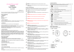
3.2 SETTING UP THE PRODUCT
Controls and indicators
1
2
7
4
5
1
1. On/Off/Volume Knob
2. Working Indicator Light
3. Headset Socket(two)
4. Transducer
5. Battery Compartment Cover
8
4
3
•
Inspect all external connections for loose connectors or frayed cables.
•
Inspect the graphics display for marks, scratches, or other damage.
•
Verify that the safety label on back of the product is clearly legible
INSTRUCTION INSPECT FOR
Examine the case connectors and accessories
Foreign substances
Damage or cracks
RECOMMENDED
REMEDY
Clean the product and its accessories as described.
Examine accessory cables
Foreign substances
Contact Our Customer
Service
Clean the cables as described in the
Section 5
Replace cable if any abnormalities are found.
Broken parts, cracks, damage, or extreme wear, broken or bent connectors and pins, after bending and flexing the cable
Examine disposable accessories
Expired PRODUCT or
Product PADS
Replace any products approaching or past their expiration dates.
WARNING: After the visual inspection, if the product and/or its accessories are damaged please contact our Customer Service.
The product will need to be returned back to us for repair. The accessories should be disposed of appropriately and replacement parts shall be ordered.
4.4 CLEANING PRODUCT AND ACCESSORIES
The following cleaning products may be used to clean the exterior surfaces of the product as well as the batteries.
•
Isopropyl alcohol (70% solution in water)
13
equipment failure and possible health hazards. The manufacturer does not, in any manner, assume the responsibility for performing the recommended maintenance schedule. The sole responsibility rests with the individuals, hospitals, or institutions utilizing the product.
4.1.1 The transducer acoustic surface is frangible and must be handle with care .Gel must be wiped off from the transducer after use. These precautions will prolong the life of the unit.
The user must check that the equipment does not have visible evidence of damage that may affect patient safety or product ’ s capability before use .The recommended inspection interval is once per month or less. If damage is evident, replacement is recommended before use.
4.1.2 To ensure the product is always functional when required, the following maintenance shall be performed.
•
Visual Inspection
•
Cleaning the product and its accessories
•
Check the battery fuel gauge
•
Testing product performance
Correction: manually calculate the FHR with hearing fetal heartbeat sound for qualification.
4.2 RECOMMENDED MAINTENANCE AND CARE
•
It is important that the product is stored at the operating temperature range if it is expected to be used. Optimal battery life will be obtained if stored and operated at room temperature. See Section 5 for temperature specifications.
•
The product requires no calibration.
4.3 VISUAL INSPECTION
The product and its accessories should be carefully inspected prior to installation, once every 12 months thereafter and each time the equipment is serviced.
•
Carefully inspect the equipment for physical damage
12
3.3 BUILD IN BATTERY
1. Open the battery cover. The rear panel is upturned. First, open the cover (5) of battery compartment.
2. Install the battery. Take out the battery connector. Then plug the battery to connector, after that put them into the battery compartment.
3. Close the battery cover. First, along the left of battery compartment latch, put the cover at the right place. Then close the cover (5).
CAUTION:
Remove these batteries if the device is not likely to be used for some time.
WARNING: Irregular treatment of batteries may be result in hazards to health and environment.
3.4 OPERATE KNOB AND INDICATOR LIGHT
There has an 'on/off/volume knob (1)', it's easy to operate. And working indicator light (2) shows working condition.
3.4.1 POWER ON
When the product is not in use, turn the 'on/off/volume knob (1)' to right for switching on the product. Indicator light (2) is on.
3.4.2 POWER OFF
When in use, turn the 'on/off/volume knob (1)' to the end of left for switching off the product. Indicator light (2) is off.
3.4.3 VOLUME ADJUSTMENT
Turn the 'on/off/volume knob (1)' to right; the sound volume will increase.
Contrary, Turn the 'on/off/volume knob (1)' to left, the sound volume will decrease.
9
3.4.4 AUDIO OUT
A socket for audio output can only be connected with a recorder complied with the requirements of IEC 60601-1.
3.5 PREPARATION
Follow these recommendations to prepare for operation:
•
Switching on by turning the 'on/off/volume key (1)'.
•
Apply coupling gel to the faceplate of probe or abdomen
•
Move the transducer slowly over the lower part of the abdomen.
10
3.6 USING PRODUCT TO DETECT
Locate the position of the fetus by hand touching, firstly to find out the best direction to the fetal heart. Place the faceplate of probe at the best position for detecting fetal heartbeat. Adjust the transducer to obtain an optimum audio signal ideally by angling the transducer around. Generally, the site of heart of fetus is 1/3 below of navel line at its earlier stage, it then moves upward with increasing of gestational period, and the site of heart of fetus will be a little deviation to left or right with different fetus. Pls. make sure that the surface of the probe should be contacted fully with the skin. After the sound become clear, it is the proper functioning. If no coupling gel, water can be used.
Gestation
Antepartum
Parturition
SECTION 4: MAINTENANCE & AFTER-SALES SERVICE
Proper maintenance of the product is very simple, yet it is an important factor of its reliability. The section describes the maintenance and service required for the product and its accessories.
4.1 MAINTENANCE
WARNING: Failure on the part of all responsible individuals, hospitals or institutions, employing the use of product, to implement the recommended maintenance schedule may cause
11
advertisement
* Your assessment is very important for improving the workof artificial intelligence, which forms the content of this project
Related manuals

advertisement