advertisement

CheckVideo Gateway for Broadband Networks
Installation Quick Reference
Step One Check Equipment and Network
Before you begin, confirm that you have the necessary equipment and are installing your CheckVideo® Gateway on a network that meets minimum network and equipment requirements. If this CheckVideo device will be monitored by a central station, please contact the central station for a username and password on their existing CheckVideo account. The central station will add the device to their account.
If this device will be self-monitored, you will be creating a CheckVideo account in
Step Four.
Network Requirements
•
Active broadband Internet connection with an upload speed of at least 512 kbps
•
If you have an active firewall, it cannot block outbound traffic on ports 123
(used for network timing), 80 (HTTP), or 443 (HTTPS)
•
DHCP enabled
•
Access to your router configuration may be necessary
Equipment Requirements
•
CheckVideo Gateway
•
CheckVideo Gateway power supply:
9-12V DC, min 1.4 amp
•
Fixed, analog NTSC/PAL cameras (not included)
•
Ethernet cable to connect the CheckVideo Gateway to the network
•
Computer or laptop with broadband access (customer provided)
(Optional:)
•
8 pin Phoenix connector for digital input/output contacts
•
Monitor for viewing live video during camera setup. This can be a
TV connected to a CheckVideo Gateway monitor connector with a BNC to RCA cable.
•
UPS power supply
Step Two Install Cameras
1.
Select a location for each camera. When placing a camera, try to follow as many of the following guidelines as possible.
•
Camera Position: Camera is mounted 8 to 20 feet above the ground and tilts downward at an angle between 15° and 45°.
•
Target Direction of Motion: People and vehicles (i.e.,
“targets”) should mostly travel from left-to-right or rightto-left across the camera view, not directly toward or away from the camera. Targets should remain in full view in the detection zone of the camera view for at least the amount of time specified in the event duration.
•
•
•
Vertical Orientation: Objects in the camera view appear upright (i.e., the camera body is not rotated clockwise or counter-clockwise with respect to the ground plane).
Adequate, Even Lighting: Lighting is constant and adequate for the light requirement of your camera.
Cabling Issues: Confirm that you can see live video from a monitor connected to the Gateway prior to connecting your cameras. Confirm that there is no video split or horizontal bar caused by cable damage, crimping, or extreme length.
•
•
Avoid Physical Obstructions or Distractions: Where possible, avoid physical obstructions and sources of constant motion
(e.g., moving doors).
Avoid Reflections, Glare, or other Extreme Lighting: Where possible, avoid reflective surfaces (e.g., mirrors, window panes, water, or polished floors) or bright lights (e.g., headlight glare, direct sunlight) directed at the camera.
Refer to the
CheckVideo Camera Placement Guide
, available www.checkvideo.net
for more detail and examples.
,
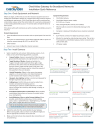
MORE EFFECTIVE - Cameras are at a
15 to 45 degree downward tilt and are mounted 8 to 20 feet high
MORE EFFECTIVE - A target traveling from left to right
LESS EFFECTIVE - Cameras are directly overhead (90 degrees) or parallel to (0 degrees) the target
LESS EFFECTIVE - A target traveling directly toward the camera
2. Extend the cable from the camera location to your Gateway.
Before running cable, make sure that it is of sufficient length and that the appropriate connectors are at each end.
3.
Make sure that all cameras have required video connections and are powered up.
LESS EFFECTIVE - Target not upright
(vertical orientation); camera body is rotated 5 degrees or more
LESS EFFECTIVE - Physical obstructions between the camera and the target
Step Three Connect CheckVideo Gateway
1.
Connect each camera’s video cable to the camera connections on the back of the Gateway.
2. Use an Ethernet cable to connect the Gateway to your network.
3.
Connect the Gateway power supply to the Gateway and plug it in.
4. Wait a few minutes for the power light on the front of the Gateway to flash rapidly.
5. When the flashing slows to one second per pulse, your device is ready for registration.
Cameras
CheckVideo Gateway back panel
Ethernet Power
Step Four Create/Access Your Account
1.
Go to the CheckVideo Dashboard login page: portal.checkvideo.net
Click the Start here link to create your account.
If you have an existing account, log in and skip to the next section to register your CheckVideo devices.
2. Complete the User Information section.
3.
In the Define Notification Methods section, for Contact
Information enter the email addresses that may receive event notifications. For MMS notifications to mobile phones, the address format will vary by carrier (ex: mobile number@
Step Five Add Gateway Device
1.
If camera will be monitored by a central station, contact them to add the device to their account.
2. If self-monitored:
•
On the CheckVideo Dashboard, click on Devices > Add Device.
•
In the Register Device section, enter the serial number found on the underside of the camera and a Device Name.
•
Click the Test Device button to make sure the CheckVideo
Software Service (CVSS) can communicate with the device.
•
(Professional Service only) Authorize service fees.
•
If prompted, update the device firmware.
mms.att.net). Check your carrier’s website for more information.
4. Choose a maximum Video Resolution for each email address. If you intend to use MMS to send video to a mobile phone, do not select a resolution higher than 480p. For 720p or 1080p, send the notifications as an attached video clip to a traditional email address (ex: jdoe@gmail.
com). Use the Test button to confirm that the video resolution is valid for your device/carrier.
5. In the Billing Preferences, choose your Service option. If you choose
Central Service, complete the form and CheckVideo Support will contact you directly.
6.
(Professional Service only) Specify method of payment, authorize service fees, and accept the License Agreement.
4. Select Notification Method - Central Stations: Select a Central
Station type that should receive alert metadata.
5. Select Notification Method - Users: Click the checkbox next to
Enter the serial number from the bottom of the CheckVideo Gateway device
Step Six Configure Device
1.
O n the CheckVideo Dashboard, click on Devices > Configure
Device.
2. Select Device: Select the device and video resolutions for event clips and DVR. CheckVideo will default both resolutions to 240p. You may wish to start with these settings. Your chosen resolution settings will depend upon the upload capacity of your Internet provider.
3.
Configure Events: Click the Edit button to create a zone for a particular object type. Then use your mouse to draw the zone by clicking the left mouse button wherever you want to define a point of the zone. The zone should cover the entire area where you want to detect an event. Enter a time span, event type, zone, and duration and click Add Event button.
Make sure
your browser is set to 100% when drawing your zone.
any user(s) who should receive notifications for this camera and their method of notification.
6.
Click Save.
A zone, defined by eight end points (first point is green; other points are blue)
A completed zone
For more detailed information, refer to the
CheckVideo Gateway for
Broadband Networks Installation Guide (available at www.checkvideo.com under the Support tab.)
© 201 7 CheckVideo, LLC.
CheckVideo is a registered trademark of CheckVideo, LLC. All rights reserved.
7CVCAQ C 000-08.01
advertisement
Related manuals


advertisement