advertisement

GreenArrays
®
Product Data Book DB006
Revised 9/23/12
G144A12
polyFORTH
®
Supplement to DB005
polyFORTH Reference
as of arrayForth
®
Rev 02a
polyFORTH® is a programming environment that runs in memory external to an F18 computer array.
In the hierarchy of programming models for the GreenArrays architecture, polyFORTH is an example of the sort of virtual machine (VM) environment which allows for the largest programs. Running slowly when compared with the internal speed of an F18, the speed is quite high enough for the parts of an application that are bulky but not time-critical. Facilities are provided for tight communication with and control over application code running in high speed node clusters.
The virtual machine was derived from that developed by Bill Muench and John Rible for use by eForth. The VM has been adapted to meet design goals for a different class of applications, and the programming system written for it has been derived from polyFORTH implementations on equipment with similar properties. The VM consists entirely of RAM resident code running in any necessary number of nodes, while the operating system resides in memory external to the chip.
Roles and responsibilities of nodes are assigned dynamically by boot software, and application code may be written in high level Forth or in F18 node level "microcode" as appropriate.
This is a 16-bit, cell addressed system with extended addressing capability up to one megaword of memory when using the SRAM controller. It is very similar architecturally to the polyFORTH system developed for the Novix NC4000P chips. This manual supplements the polyFORTH Reference by documenting this system's departures beyond the model described by that Reference.
This book will familiarize you with the structure, organization, operation, maintenance and use of polyFORTH as provided for the G144A12 chips.
Your satisfaction is very important to us! Please familiarize yourself with our Customer Support web page at http://www.greenarraychips.com/home/support . This will lead you to the latest software and documentation as well as resources for solving problems and contact information for obtaining help or information in real time.
DB006 G144A12 polyFORTH Supplement
Contents
Introduction .............................................................................. 5
The Virtual Machine .................................................................. 8
polyFORTH Model Differences ................................................. 16
Documentation and Source Management Facilities .......................................... 17
2
Copyright© 2010-2011 GreenArrays, Inc. 9/23/12
Copyright© 2010-2011 GreenArrays, Inc. 9/23/12
DB006 G144A12 polyFORTH Supplement
System Features ...................................................................... 21
Creating and Managing BACKGROUND tasks .....................................................27
Creating and Managing TERMINAL tasks ............................................................27
Operation and Maintenance ................................................... 39
3
DB006 G144A12 polyFORTH Supplement
Maintaining the polyFORTH Nucleus ............................................................. 44
Application Extensions ............................................................. 47
Data Book Revision History ...................................................... 49
4
Copyright© 2010-2011 GreenArrays, Inc. 9/23/12
DB006 G144A12 polyFORTH Supplement
1. Introduction
Imagine being able to create a computer, perfectly tailored to meet the requirements before you, in software and then port your favorite operating environment to run on it. It has turned out that this is a very simple and relatively easy thing to accomplish using the GreenArrays architecture.
This system was created to act as the foundation for the Automated Testing System (ATS) used in testing our chips, and for the complete development system running natively on our chips rather than on a host computer. It may also be used as an application platform in its own right, integrating high speed processing in F18 nodes with lower speed, bulkier software (such as Internet Protocols) running on the virtual machine itself.
The system consists of a software-defined virtual machine comprised of several nodes and a suitably sized external
SRAM, and a high level polyFORTH system written to run on that virtual machine. The architecture of this polyFORTH system is very similar to that of the system made for the Novix NC4000 chips.
This manual describes the standard Virtual Machine and polyFORTH operating system underlying the above
GreenArrays environments. When used for other applications the system may be customized in high level software as you wish. In addition, the Virtual Machine itself is open for customization, by adding instructions or by changing the way in which those provided behave. In fact, it is feasible to interactively work with with coprocessor code using the
IDE while the polyFORTH system is actually operating.
This book will familiarize you with the structure, organization, operation, maintenance and use of polyFORTH as provided for the G144A12 chips. The ATS, the F18 development system and any other I/O options and applications based on this system are documented separately.
Installation procedures make use of the arrayForth system; see the System Maintenance chapter at the end of this document. To facilitate installation, a Terminal Emulator is provided; this emulator is actually saneFORTH, a strippeddown Win32 Forth system derived from polyFORTH, provided by ATHENA Programming, Inc., on the same basis as is all the other software distributed by GreenArrays.
1.1 Related Publications
DB005 polyFORTH Reference Manual is the foundation for understanding the polyFORTH model, tools, and development methods. This manual supplements that Reference; it assumes you understand the material in the Reference, documenting only implementation-specific details. We recommend that you familiarize yourself with the Reference before studying this manual.
DB004 arrayForth User's Manual describes the tools and development methods used for working with F18 code. This manual assumes you have familiarized yourself with arrayForth operations.
DB001 F18A Technology Reference serves as the Programmer's Reference for the F18 computers and I/O architecture.
DB002 G144A12 Chip Reference documents the configuration of this specific chip. Both DB001 and DB002 should be understood before you begin programming F18 code.
DB003 Evaluation Board Reference Manual contains information with which every user of this board should be familiar. The polyFORTH release may be adapted for other hardware configurations but is shipped with configuration settings suitable for running on the EVB001 Evaluation Board.
Application Notes exist, or are planned, for many software modules that are either intrinsic to polyFORTH
(such as the SRAM Control Cluster, Snorkel, and Ganglia) or optional (such as the Ethernet NIC.)
Copyright© 2010-2011 GreenArrays, Inc. 9/23/12 5
DB006 G144A12 polyFORTH Supplement
1.2 Getting Started (Quick Setup)
If you wish to run this system before reading all of the recommended documentation, please use this check-list.
1. Ensure that you have downloaded and are using the latest arrayForth release.
2. Perform the initial check-out procedures shown in section 1 of AN004, Getting Started with Eval Board
EVB001. You should have received a printed copy of this document with your board(s), but it's also available from our website. This will ensure that your hardware is working, and that the jumpers are in their standard configurations. If you have not written to your SPI flash, the simple confidence test using eForth (AN004 section 1.5) is a good functional check of that circuitry.
3. Be sure you have edited the COM port numbers for USB ports A and C in arrayForth block 202, and rebooted or warm started arrayForth as described at the end of DB004, arrayForth User's Manual, section 11.2.1. You will be using port A to load polyFORTH or to burn it into flash. Although port C is not required to run polyFORTH, you may as well do this now and get it over with.
4. Initially you will need to use the Win32 terminal emulator provided with arrayForth to talk to polyFORTH and
this terminal emulator. You should check and, as necessary, edit the COM port number in the block named
SERIAL at this time.
1.3 Documentation Conventions
1.3.1 Numbers
Numbers are written in decimal unless otherwise indicated. Hexadecimal values are indicated by explicitly writing
“hex” or by preceding the number with the lowercase letter “x”. In colorForth coding examples, hexadecimal values are italicized and darkened.
1.3.2 Node coordinates
Each GreenArrays chip is a rectangular array of nodes, each of which is an F18 computer. By convention these arrays are visualized as seen from the top of the silicon die, which is normally the top of the chip package, oriented such that pin 1 is in the upper left corner. Within the array, each node is identified by a three or four digit number denoting its
Cartesian coordinates within the array, with the lower left corner node always being designated as node 000. The low order two digits of a node number are its X axis position relative to this corner, and the third and, where needed, fourth digits are its Y position relative to this corner. Thus, for a GA144 chip whose computers are configured in an array of 18 columns and 8 rows, the numbers of the nodes in the lower right, upper left, and upper right corners are
017, 700, and 717 respectively.
1.3.3 Bit Numbering
Binary numbers are visualized as a horizontal row of bits, numbered consecutively right to left in ascending significance with the least significant bit numbered zero. Thus bit n has the binary value 2 n
. The notation P9 means bit 9 of register
P, whose binary value is x200, and T17 means the sign bit of 18-bit register T.
6
Copyright© 2010-2011 GreenArrays, Inc. 9/23/12
DB006 G144A12 polyFORTH Supplement
1.4 Key Properties
Although this system is designed to feel familiar to a programmer acquainted with polyFORTH, it has several individual properties that must be respected. Later sections will detail this system's departures from the generic polyFORTH model, and the operation of major components. Bear this summary in mind while reading the rest of this document.
1. Cell addressing: Main (external) memory is addressed by the "hardware" in 16-bit cells. By default, Forth words produce and consume cell addresses (shown as a in stack comments), and by default string operations such as MOVE take counts in units of cells. Byte addresses (shown as b in stack comments) are produced and consumed only where explicitly indicated; byte string operations such as CMOVE take counts in units of bytes.
The byte address of a cell is obtained by doubling that cell's address; this address denotes the most significant octet of that cell, and incrementing this byte address by 1 denotes the least significant octet of that cell.
2. Memory hierarchy: 1 megaword (2 megabytes) of external memory are supported. The first 32k words, called
"main memory", are both byte and cell addressable in 16 bits. The next 32k words, called "high memory", are only cell addressable in 16 bits. The remainder, called "extended memory", requires a double-precision address. An hierarchy of access and allocation functions exists for these three classes of external RAM.
3. Direct code execution: There is no "code field" as such; instead that position relative to a head is the first VM instruction of actual code executed for any word of any type. Execution tokens (xt) point directly to the start of this VM code. The "parameter field" of a CONSTANT, VARIABLE, or instance of any other word defined using CREATE DOES or CREATE DOES> lies at the cell following the xt address.
4. No Assembler: There is no need for an Assembler as such since the VM instructions are Forth primitives and can all be generated using the Forth Compiler.
5. Optimal coding practices: Execution times of VM primitives are dominated by the number of external SRAM cycles required by each, and thus programming for maximum performance (and minimum energy) will require attention to this detail. For example, a FOR NEXT loop is vastly superior to a DO LOOP .
6. Dictionary Structure: This system uses an "active" compiler such that many Forth primitives have distinct compiling behavior versus interpretation behavior. As a result, each vocabulary is mapped into two logical threads, one for interpretation and the other, where appropriate, for compilation. The dictionary management and search mechanisms are extended accordingly. Additionally, experience has revealed serious flaws in the mixing of truncated and full-length names; this system always uses full-length names.
7. Utilities: Many improvements in programmer tools and utilities have evolved since the era of the model described by the Reference Manual. These improvements are incorporated in this system.
8. I/O Differences: Unlike other computers this one has no interrupts per se, and all I/O is implemented using one of two methods: Polled operations supported by cooperation between I/O nodes and the VM, or memory mapped ("bus mastering") devices communicating with the SRAM cluster. In environments of this sort, the equivalent of an "interrupt" is the direct awakening of a polyFORTH task by a bus mastering node or cluster.
1.5 Compliance with Standards
Our motivation for creating this system was to maximize performance, flexibility and functionality. Compliance with the FORTH-83 Standard would have required byte addressing; compliance with ANS Forth would have required either byte addressing or the storage of characters in cell sized containers. Compliance with any of these most fundamental requirements of either standard would have forced unacceptable trade-offs conflicting with the above motivations.
Therefore, while not unconventional for polyFORTH systems on such hardware, this system cannot comply with either of the Standards named due to its definition of separate cell and byte address spaces and their mapping onto the same memory.
Copyright© 2010-2011 GreenArrays, Inc. 9/23/12 7
DB006 G144A12 polyFORTH Supplement
2. The Virtual Machine
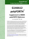
The polyFORTH Virtual Machine (pFVM) is a software-defined CPU consisting of six nodes (005, 006, 105, 106, 205 and
206.) This CPU is one of the three principal clients of the external SRAM control cluster, consisting of four nodes (107,
007, 008 and 009.) In the present version, nodes 205 and 206 are entirely available for application microcode and the basic CPU is implemented by the remaining four nodes. The eight nodes constituting the basic pFVM are shown highlighted with green background in this diagram of their immediate neighborhood:
200 ex4 term
Rx
201 wire
202 wire
203 wire
204 wire
205 optional applic copro- cessor
Exxx
206 optional applic copro- cessor
Axxx
207 optional
SRAM client: snorkel
208 209
100 ex4 term
Tx
000
101 wire
001
102 wire
002
103 wire
003
104 e4 term ctl
004
105 bitsy
Cxxx
005 active coprocessor
Fxxx
106
Stack
(SRAM client)
8xxx
107
SRAM interface
Basic pFVM
108 optional
SRAM client:
NIC
006 active copro- cessor
Bxxx
007
SRAM data bus
008
SRAM ctl lines &
2 addr
109
009
SRAM addr bus
Flows within VM CPU
Flows for legacy terminal interface
SRAM client service
Flows within SRAM control cluster
polyFORTH Virtual Machine for GA144-1.2
The ten nodes of the pFVM may optionally cooperate with nearby nodes depending on the application. The SRAM control cluster may have two other autonomous principal clients (108 and/or 207) shown in pink.
The virtual CPU may be extended with application specific functions that interface through (and may be housed in) nodes 004, 305 and/or 306, shown in lavender, or any nodes that may be reached through these. As noted earlier, nodes 205 and 206 are reserved for application microcode, as is part of the RAM in node 005.
One method of communicating with the pFVM is to use a terminal interface such as the full duplex version shown in yellow; this is not optimal but is simply one way of arranging the necessary “wiring”.
Like any Virtual Machine, the pFVM executes pseudo-instructions from external memory. This chapter describes this virtual machine and its instruction set with sufficient detail to program it in “machine language” or to write compilers or assemblers for the pFVM.
8
Copyright© 2010-2011 GreenArrays, Inc. 9/23/12
DB006 G144A12 polyFORTH Supplement
2.1 Memory Model
External memory is addressed in 16-bit cells using cell addresses and 8-bit bytes using byte addresses. Doubling a cell address yields the byte address of the high order octet of that cell. The addresses consumed and produced by Forth words are either byte addresses or cell addresses based on the lessons learned through years of experience with systems that support both address units. Most byte operations must be programmed in high level VM code.
The principal VM environment exists within the 32K words of memory starting at address zero. Unrestricted high level code and single precision byte addressing work only in this area. Single precision cell addressing, and the ability to execute VM instructions covers the full 64K words of low memory, and double precision cell and byte addressing covers all of physical memory. No form of memory mapping or segmentation is supported.
There may be up to three first-tier Memory Masters; the pFVM is but one of these. One of the special operators that can access all of memory is “compare and exchange”, useful for coordinating the work of memory masters.
Mechanism exists for Masters to suspend operations until stimulated by other Masters.
2.2 Execution Model
The VM microcode functions as a central processor interpreting VM code residing in external memory. Consecutive pseudo-instructions are fetched from external memory and interpreted by the microcode.
2.2.1 Pseudo-registers
The VM maintains several state variables within its nodes; these are referred to by their names in the following sections.
Name
p r i sp t s
Purpose
Instruction Pointer
Return Stack Pointer
Top element of Return Stack
Data Stack Pointer
Top element of Data Stack
Second element of Data Stack
Where Maintained
F18 stack in Bitsy node
F18 stack in Stack node
2.2.2 Pseudo-Instructions
The pFVM fetches 16-bit cells from the instruction stream by reading the memory addressed by p and postincrementing p . When fetched as an instruction, a cell value is interpreted as follows:
15 14 13 12 11 10 9 8 7 6 5 4 3 2 1 0 Function
0 High Level Execution token (external RAM address) Call pFVM code in low external RAM
1 1 0 0
1 1 1 0
1 1 1 1
1 0 0 0
1 0 1 0
1 0 1 1
00 ea F18 RAM/ROM/Port address
Call F18 definition in Bitsy node 105
Call F18 definition in node 205 through
up port of bitsy node
Call F18 defn in node 005 down bitsy
Call F18 definition in Stack node 106
Call F18 defn in node 206 up stack
Call F18 defn in node 006 down stack
Executing a high level execution token is a classical Forth call, pushing p onto the return stack, setting p to the given address, and continuing to fetch and execute instructions based on the new value of p . The other instructions constitute calls to microcoded routines in one of the six accessible nodes.
Copyright© 2010-2011 GreenArrays, Inc. 9/23/12 9
DB006 G144A12 polyFORTH Supplement
2.3 Implementation
The principal nodes comprising the polyFORTH VM are named Bitsy and Stack . The stack node is the true external
RAM client, holding stack pointers and caching the top two elements of the data stack. The bitsy node is the heart of the interpreter, defined by run .
2.3.1 Interaction with RAM control
The SRAM control node 107 accepts requests from three possible clients, of which the polyFORTH stack node is one. It performs atomic operations as requested by its client(s). The set of functions supported is open, and the architecture allows for replacement of this controller with other types as we have done in the past (five-node SDRAM controller).
2.3.2 Interactions among VM nodes
Bitsy embodies the "main program" of the VM. The other five processor nodes only act under the direction of Bitsy.
For stack node instructions, Bitsy sends the following through its left port to the stack node:
The instruction word
@p @p . .
The unshifted instruction word
The instruction word shifted left 3 bits
The instruction word
sco . . .
(a call to the sco decoding routine; subsequent decode and action is the responsibility of the stack node.)
The coprocessor nodes 005 and 205 receive instructions from Bitsy, while 006 206 receive theirs from the stack node.
The protocol is the same in each case.
A coprocessor node perpetually executes a three word routine called idle . It is worthwhile to examine the code:
xqt @b push ex idle @p !b xqt ; / drop !p . . /
Each coprocessor is offering the instruction word
drop !p . . to its controlling node. When the controlling node determines that an instruction is directed at one of its coprocessors, the controlling node has on its stack the original
VM instruction under a shifted copy of the same. The controlling node calls the port leading to the appropriate coprocessor, executing the instruction it finds there. This has the effect of dropping the shifted VM instruction and writing the original VM instruction to the coprocessor.
The coprocessor, meanwhile, has jumped to xqt where it receives the VM command and effectively executes it by calling the memory or port address contained in the instruction. Upon return the coprocessor falls through into idle where it once again presents the above instruction to the controlling node.
While a coprocessor is working on an instruction, its controlling node is effectively enslaved to the coprocessor which may feed instructions to it for port execution, thus giving the coprocessor access to everything known to the controlling node. At the end of the instruction and before returning to idle , the coprocessor must feed a return to the controlling node.
Coprocessors of the stack node have access to sp, t, s, and main memory as well as all the code in the stack node.
Coprocessors of Bitsy have access to r, i, p, and all the code in BItsy, as well as main memory and the stack node's other resources by commanding the stack node through Bitsy.
In addition it is possible for a coprocessor to extend the VM further by using a different idle routine. In that case it would probably wish to accept both shifted and unshifted VM instructions and decode them further as the stack node does; there are two unused bits in the VM instruction that would allow for considerable extension.
10
Copyright© 2010-2011 GreenArrays, Inc. 9/23/12
DB006 G144A12 polyFORTH Supplement
2.3.3 Bitsy Node (105)
The register assignments in the Bitsy node are:
T holds 16-bit instruction pointer p (word address in low 64k words of external RAM.) Address of the next word to execute.
S holds the top element of the external return stack, referred to as i .
Third stack item holds 16-bit Return Stack pointer r (word address in low 64k words of external RAM.) The external return stack grows downward in memory and r holds the address of the next unused cell.
A is the port address (right) for the serial terminal interface node (104).
B is the port address (left) for the stack node (106).
P is normally in bitsy RAM.
The primitives and other routines in the Bitsy node are as follow:
F18 Symbol pF Symbol Function
'else bx@ bx!- dec
@2tos bpshw
'rp@
'lit inc
'con
'var
'exit popi geti bpopw
'tor
'r@
'rfrom
'exe xxt run
'if else
---
(a-x) Fetches a word from external memory by commanding the stack node to do this with its x@ function. bx@ is only used inside F18 code.
(ax-a) Stores x in external memory at a using the x! function of stack node, postdecrementing a . Used internally to push data onto return stack.
---
---
---
RP@ lit
--- lit;
(u-u') Decrements the argument by 1.
(a) Pushes the memory cell at a onto the external stack.
(n) Pushes n onto external stack using the pshw function of the stack node.
(rip-rip) Pushes the address of top element of external return stack onto external stack. Note that this is one less than r .
(rip-rip') Literal fetch. Pushes next word of instruction stream onto external stack.
(u-u') Increments the argument by 1.
(rip-r'i'p') Pushes the contents of the next cell in instruction stream onto the external stack and exits the current definition. Generic primitive for inline constant . var;
EXIT
(rip-r'i'p') Pushes i onto external stack then falls through into 'exit . Generic primitive for inline create .
(rip-r'i'p') The classical exit function. Replaces instruction pointer i with an address popped from the external return stack.
--- (r/p-r'ip) Called with new p on return stack, pops i from return stack and sets up to execute at new p.
(r/p-rip) Like popi but fetches i from return stack, no pop. ---
---
>R
(-w) Pops w from the external stack into our node. Internal use.
(rip-r'i'p) Classical Forth >R . Pops a word from external stack and pushes to external return stack.
(rip-rip) Pushes the top element of external return stack onto the external data stack. I
R> (rip-r'I'p) Classical R> . Pops a word from the external return stack and pushes it onto the external data stack.
EXECUTE (rip-rip) Classical EXECUTE . Executes the VM instruction on top of the external stack (High level or microcode.)
---
(ripx-rip) Executes the VM instruction on top of f18 stack. If a bitsy node instruction, jumps to its address; if another node, decodes far enough to pass along with appropriate protocol. If high level definition, pushes return stack and replaces p with its address. In all
--- if cases returns to the caller of xxt with the op either completed or in progress in another node.
(rip-rip) Main program of VM, Infinite loop. Fetches next word in the external instruction stream addressed by by p and increments p , then interprets the instruction word with xxt .
(rip-rip') Classical Forth IF . Pops external stack; if value nonzero, skips next word of
Copyright© 2010-2011 GreenArrays, Inc. 9/23/12 11
DB006 G144A12 polyFORTH Supplement
'rx?
'tx?
'rp!
RX?
TX?
RP! instruction stream. Otherwise replaces the instruction pointer (p) with that next word.
(-w) Reads a word from the serial terminal interface node and pushes it onto external stack.
(func-result) Plumbing. Commands stack node to send us its T value which is passed to the serial terminal interface node. We then read a word from the serial interface node and send it back to the stack node to replace its prior T value.
(rip-r'i'p) Materializes the cached i onto the external return stack. Pops a word from external stack, increments it and uses it as new return stack pointer r . Pops i from external return stack to cache it locally.
2.3.4 Bitsy Down Node (005)
This node contains overflow functions from Bitsy with room left for application functions. Its register assignments are:
B is the port address (down) for the Bitsy node (105).
A is available for application assignment and will typically contain the address of the right port for communication with node 004..
As a coprocessor node, it is continually executing the idle routine. Its primitives and routines are:
F18 Symbol pF Symbol Function xqt idle
'next
---
--- next
Fetches VM instruction from controlling node and executes it.
Loop that provides service to controlling node.
Classical Forth NEXT which falls through when i is 0.
<49 words of node RAM uncommitted>
2.3.5 Bitsy Up Node (205)
This node is set aside for application microcode. It includes optional routines to facilitate interactive testing whereby the IDE is used to compile and test new microcode on a live polyFORTH system.
B is the port address (up) for the Bitsy node (105).
A is available for application assignment.
As a coprocessor node, it is continually executing the idle routine. Its primitives and routines are:
F18 Symbol pF Symbol Function xqt idle start free
---
---
---
-N205
Fetches VM instruction from controlling node and executes it.
Loop that provides service to controlling node.
Callable from IDE to initiate coprocessor mode.
Terminates idle to allow IDE access to the node.
<57 words of node RAM uncommitted. 61 available if start and free removed.>
12
Copyright© 2010-2011 GreenArrays, Inc. 9/23/12
DB006 G144A12 polyFORTH Supplement
2.3.6 Stack Node (106)
The register assignments in the Stack node are:
T holds the top element of external stack, commented as t .
S holds the second element of external stack, commented as s .
Third stack item holds 16-bit Data Stack pointer sp (shown in stack comments as p ). It is a word address in low 64k words of external RAM.) The external data stack grows downward in memory and sp holds the address of the topmost active cell. The top two elements t and s are not included in the external stack but are pushed there when the stack pointer is replaced.
A is unassigned.
B is the port address (right) for the SRAM interface node.
P is normally the port address (left) for the bitsy node.
In stack comments, p denotes the stack pointer which by default resides underneath S . The external data stack grows downward in memory and the stack pointer holds the address of the topmost active cell.
The primitives and other routines in the Stack node are as follow:
F18 Symbol pF Symbol Function x! ex! x@
---
---
@
(wa-3-) Writes w to external RAM at address 0:a using the SRAM interface node.
(pst-p'54) Writes w to external RAM at address h:a . Ones complemented address signals the SRAM interface that this is a write.
(a-2-w) Classical Forth @ (a-w) .Reads w from external RAM at address 0:a using the SRAM interface node. ex@ cx?
---
---
'1+ mask
'2/ popt
'au! popst pops pop43
'1- psht pshs pshw
'sp!
'drop
'over sco
'qdup
'dup
'swap
'2*
1+
---
2/
---
!
---
---
---
1-
---
---
---
SP!
DROP
OVER
---
---
DUP
SWAP
2*
(ah-w) Reads w from external RAM at address h:a .
(wahx-f) Compare & Exchange. If the word in external RAM at address h:a has the value x , stores w there and returns f as nonzero Otherwise does not alter RAM and returns f as zero.
(n-n') Increments a value by one, modulo 2
16
.
(u-u') Returns modulo 2
16
of its argument.
(t-t') Shifts a 16-bit value right one bit modulo 2
16
with sign extension.
(p-xp't) Pops an item from the external data stack with abandon; x is the stack pointer before incrementation.
(pan-p43) Classical Forth ! (wa).
(p-xxp'st) Pops two items from the external data stack with great abandon.
(pt-xp'st) Pops an item from the external data stack underneath the value t .
(pst-xxp'43st) Pops the next two items from the external data stack underneath the values of s and t with great abandon.
(n-n') Decrements a value by one, modulo 2
16
.
(pt-p') Pushes t onto the external data stack.
(pst-p't) Pushes s onto the external data stack retaining t .
(pstw-p'tw) Pushes w onto the logical stack, pushing s into external RAM.
(ptp'-p"s't') Switches to use data stack whose top address is given. The old t value is saved on the old stack first, then the local cache is refreshed from new stack.
(pst-p'3s) Classical Forth DROP (x).
(pst-p'ts) Classical Forth OVER (ab-aba).
(x3) Finishes decode and execution of a VM instruction x in stack node or one of its coprocessors. Top of stack is x shifted left 3 bits.
(pst-pst|p'tt) Classical Forth ?DUP .
Disabled.
(pst-p'tt) Classical Forth DUP (x-xx).
(pst-pts) Classical Forth SWAP (ab-ba).
(n-n) Doubles a value, modulo 2
16
.
Copyright© 2010-2011 GreenArrays, Inc. 9/23/12 13
DB006 G144A12 polyFORTH Supplement
'or
'xor
'and
'neg
'inv
'zeq
'zlt
'um+
'nop
'-
'+
OR
XOR
AND
NEGATE
INVERT
0=
0<
UM+
NOP
-
+
(pst-p'3w) Classical Forth (inclusive) OR (nn-n).
(pst-p'3w) Classical Forth (exclusive) XOR (nn-n).
(pst-p'3w) Classical Forth AND (nn-n).
(n-n) Classical Forth NEGATE , modulo 2
16
.
(n-n) 1's complement inversion of full 18 bits, modulo 2
16
.
(n-f) Classical Forth 0= (n-t). True is 16 1-bits.
(pst-p'3w) Classical Forth (inclusive) 0< (n-t). True is 16 1-bits.
(uu-uc) 17-bit sum of 16-bit numbers.
Truly does nothing.
(pst-p'3n) Classical Forth - (nn-n).
(pst-p'3n) Classical Forth + (nn-n).
2.3.7 Stack Down Node (006)
This node contains overflow functions from Stack with room left for application functions. Its register assignments are:
B is the port address (down) for the Stack node (106).
A and the carry flag are reserved for math routines and may be used to hold state between commands.
As a coprocessor node, it is continually executing the idle routine. Its primitives and routines are:
F18 Symbol pF Symbol Function xqt idle
''s
43xp pops;
'ex@
'ex!
'cx?
'mk!
'sus
---
---
'S
---
Executes in stack node: 'sp@ (pst-p'tp") Classical Forth 'S (-a). Pushes stack pointer which is the external memory address at which the initial t would be stored.
(op) Internal function that commands stack node to do its pop43 (pst-p43st), then execute the instruction word given (op), and finally pop s from external stack. op is assumed to consume 3 arguments, or to take 4 arguments and return one result.
Ends a coprocessor operation by having stack node perform its pops .
---
XM@
XM!
XCX
(pst-p'3w) External stack (ah-w) . Fetches w from external RAM at address h:a .
(pst-p'54) External stack (wah). Writes w to external RAM at address h:a .
(pst-p'5f) External stack (wahx-f) Compare & Exchange. If the word in external
RAM at address h:a has the value x , stores w there and returns f as nonzero
Otherwise does not alter RAM and returns f as zero.
MK!
(pst-p'54) External stack (msk f 0). f=1 sets SRAM master enable mask to msk .
f=0 posts stimuli for master(s) given by msk . In both cases the port write bits of the mask are significant, all others must be zero. See AN003, SRAM Control Cluster, for more information about this function.
SUSPEND Suspends VM execution, waiting for a stimulus from one of the other masters on the SRAM cluster.
2.3.8 Stack Up Node (206)
This node is set aside for application microcode. It includes optional routines to facilitate interactive testing whereby the IDE is used to compile and test new microcode on a live polyFORTH system.
B is the port address (up) for the Stack node (106).
A is available for application assignment.
As a coprocessor node, it is continually executing the idle routine. Its primitives and routines are:
F18 Symbol pF Symbol Function
14
Copyright© 2010-2011 GreenArrays, Inc. 9/23/12
DB006 G144A12 polyFORTH Supplement xqt idle start free
---
---
---
-N206
Fetches VM instruction from controlling node and executes it.
Loop that provides service to controlling node.
Callable from IDE to initiate coprocessor mode.
Terminates idle to allow IDE access to the node.
<57 words of node RAM uncommitted. 61 available if start and free removed.>
Copyright© 2010-2011 GreenArrays, Inc. 9/23/12 15
DB006 G144A12 polyFORTH Supplement
3. polyFORTH Model Differences
This section parallels the structure of the polyFORTH Reference Manual, detailing differences suitable for coverage in this format and referring to other sections for those requiring more elaborate documentation. Headings are numbered to correspond with those in Chapters 1 through 4 of the Reference Manual for your convenience.
3.1 Chapter 1: Introduction
3.1.1 Forth Language Features
The most pervasive difference lies in the memory model with its mapping of byte and cell address spaces. This has made for a very efficient implementation and in practice does not cause as much trouble as one might think. The basic rule is that by default all addresses are cell addresses, and for words using counts the counts are in the units of the associated addresses. Although it may be redundant, this point is made where relevant in this introductory section.
3.1.1.1 The Dictionary
The Dictionary is linked as in generic polyFORTH and organized into eight logical vocabularies. There are however sixteen chains instead of eight, so that the active compiler may be conveniently supported. Thus the tables in
CONTEXT and GOLDEN are twice the generic length.
WIDTH and tilde ~ do not exist in this system. All word names are stored in the dictionary at their full lengths, up to
31 characters, and dictionary searches always compare all characters.
There is no "code pointer" in this system. Instead the code field is merely the start of executable code. Execution
Tokens, in ANSI paralance, are the addresses of code fields. Parameter fields, if any, follow one cell of code when a definition lies in main memory.
3.1.1.2 Parameter and Return Stacks
The VM supports arbitrarily large stacks, as contrasted with F18 nodes which have strictly limited stack space. Usage is conventional although, of course, S0 and 'S deal in cell addresses. The vocabulary for accessing the return stack is actually a bit richer than stated in 1.1.3 of the Reference Manual.
3.1.1.3 Text Interpreter
The definition shown for INTERPRET is slightly different in this system to account for distinct cell and byte addressing.
Please see the nucleus source code.
3.1.1.4 Numeric Input
The user variable 'NUMBER has a cell address so its follower is 'NUMBER 1+ .
3.1.1.5 Address Interpreter
This system does not have an address interpreter as such, since its "machine language" is designed to directly support
Forth primitives.
3.1.2 polyFORTH Operating System Features
This is a stand-alone, native system, complete with user programmable hardware/firmware, and a sea of available coprocessors for I/O, signal processing, and any other conceivable use.
3.1.2.1 Memory Organization
The basic memory model for polyFORTH systems, as shown in the Reference Manual, applies to the lowest-addressed
32k words of external RAM. This region is fully addressable, both as bytes and cells, using a single precision address.
This system supports two additional classes of external memory: The second 32k words, called "high memory", and then the full 1 megaword, called "extended memory." High memory is accessible with a 16-bit cell address; facilities
16
Copyright© 2010-2011 GreenArrays, Inc. 9/23/12
DB006 G144A12 polyFORTH Supplement are provided for allocating this area for data and also for code that does not contain string literals. Extended memory is accessible in any desired way using double precision addresses.
3.1.2.2 Disk Block I/O
The purposes of this system are served well by very basic support for mass storage. By default there are four block buffers. BLOCK and BUFFER take single precision block numbers and return cell addresses. The infrastructure is extended for 32-bit block addressing when the MMC mass storage is added. The PREV table is customized. Status information is stored in DISK 1+ and the block number just written is stored starting at 'BUFFER 1+ . The mapping of BLOCK address space to devices is configured using a table; PLEAT is not used and this word is not provided.
The coding example shown in the Reference Manual for VIRTUAL assumes a byte addressed virtual memory. By replacing 1024 with 512 in the definition of VIRTUAL the array would be cell addressed and the example would be correct.
3.1.2.3 Multitasking
The multi-tasking architecture in this system is conventional; STATUS contains an instruction and that instruction is either an unconditional jump (else) to the next task's STATUS , or is a call to WAKE which is a short line of VM code.
The prose in 1.2.3 the Reference Manual may imply that STOP puts a task to sleep by storing a jump instruction in its
STATUS . That is not correct; it is WAKE that marks a task asleep, and STOP merely exercises the dispatch loop.
PAUSE on the other hand does store WAKE into STATUS. The extended description of multi-tasking in the Reference
Manual is more clear on this vital point
As is noted elsewhere, this virtual machine has no interrupts as such. A task may be awakened by another task, or by another memory mastering node(s) which knows how to awaken the task by storing directly into its STATUS cell.
3.1.3 The polyFORTH Assembler
There is no need for an Assembler as such in this system. The compiler learns how to generate VM instructions as follows:
Target compilation uses the defining word f18 to make "equates" whose values are f18 instructions. Whenever the
VM node code is changed, new addresses are manually transcribed into the f18 definitions in the nucleus.
The defining word uCODE is given an instruction value and generates an active compiling word (corresponding with
IMMEDIATE in conventional Forth systems) whose behavior is to append that instruction to a definition being compiled. For example, 'drop is the f18 equate for an instruction that drops a word from the VM stack. DROP is a
uCODE definition that causes a 'drop instruction to be compiled. In order for DROP to be usable in interpretive code, the nucleus contains a colon definition as follows:
: DROP DROP ;
3.1.4 System Configuration and Electives
The procedures used for this purpose are conventional, still beginning with block 9, but other blocks in [0..60[ have been rearranged. Read block 9 and the code it loads to see the sequence applicable on this system. In this process you will note other discrepancies with specifics described in the Reference Manual; for example, <CREATE> is defined in
3.1.5 Documentation and Source Management Facilities
This system uses conventional "shadow blocks" for primary code documentation, and the organization and style of the source code is conventional for polyFORTH systems. Some concessions have been made to conserve mass storage space since the primary boot medium on the evaluation board is an SPI flash limited to 1 megabyte of storage.
Copyright© 2010-2011 GreenArrays, Inc. 9/23/12
17
DB006 G144A12 polyFORTH Supplement
The assignment of letters for stack effect comments has been changed to reflect the coexistence of cell and byte addressing:
c
a
b now denotes any octet sized value... a byte, or a character that may fit into a byte. now denotes a 16-bit cell address. now denotes a 16-bit byte address.
See Source Code Management below for the consolidated and updated tools provided with this system.
3.2 Chapter 2: Basic Forth Vocabulary
This implementation uses 16-bit cells, twos complement arithmetic, and by default all addressing is in cell units.
Double cells are stored with most significant cell first in memory. Big-endian byte addressing is simulated as described later. Enhancements are documented later on.
3.2.1 Stack Operations
Parameter stack operations are conventional; note that 'S returns a cell address so offsets into the stack are half what the examples show. PICK and ROLL are deprecated since both are apocryphal and ROLL is abysmally inefficient.
Memory operations are conventional except for the cell addressing and the hierarchy of available memory, as described later. Half-cells do not exist so the half-cell vocabulary does not exist.
Return stack operators are conventional except that R@ is apocryphal and is deprecated.
Conveniences are conventional except that ' (tick) yields an interpretable execution token (executable versions for primitives) and that the execution token is not a parameter field address.
3.2.2 Arithmetic and Logical Operations
Some operations may be available only in compiling forms and may not be interpreted.
Deprecated functions: M-
The division operators will be changed soon. Not all have been tested for full range. Relationals such as < MAX MIN are implemented using the circular model, so are not full range; for full range use U< or WITHIN .
Truth values are conventional for late polyFORTH systems. Any word that consumes a flag will interpret zero as false and any nonzero value as true. Any word that produces a flag will produce "clean" values (0 for false, -1 for true) unless the word is documented to produce a "dirty" value (any nonzero for true.) NOT is equivalent to 0= and therefore will invert the interpretation of any flag, dirty or clean.
3.2.3 Character and String Operations
In general character oriented words produce and consume byte addresses and counts in the manner most natural for their intended uses. For example, WORD places counted strings at HERE 1+ and returns a cell address. COUNT takes a cell address, returning a byte address and byte count. Those words dealing in byte addresses and/or counts are listed in later sections. " is not presently implemented.
3.2.4 Program Structures
FORTH, Inc. systems have always supported flexible program structuring. During compilation, the parameter stack holds cell addresses and is what ANS Forth calls the "control flow stack." These addresses may be manipulated freely to build useful structures, such as multi-exit loops, that are more efficient of code and of execution time than the less flexible alternatives. Please see ANS Forth for examples of what may be accomplished.
18
Copyright© 2010-2011 GreenArrays, Inc. 9/23/12
DB006 G144A12 polyFORTH Supplement
This sytem includes AHEAD which compiles an unconditional jump to be resolved later. In addition, the VM directly supports FOR NEXT loops which are recommended over all forms of DO loops for efficiency. DO loops are still implemented to facilitate quick code conversion, but only as high level code.
Exception handling is facilitated by CATCH and THROW as described in ANS Forth. These are not completely integrated with ABORT yet, but will be eventually in the same way as they've been adopted in saneFORTH.
Per saneFORTH conventions, QUIT does not clear the parameter stack.
Finally, in all the examples in 2.4.8 of the Reference Manual, many examples would require conversion for execution token addresses and address offsets.
3.2.5 Interpreter and Compiler Details
For operation of ['] and other aspects of dictionary searching, see the section on Active Compiler later on. 'HEAD returns xt instead of PFA . CVARIABLE and RECURSE are deprecated.
3.3 Chapter 3: System Functions
3.3.1 Vectored Routines
Generic vectors are supported. This system adds some important ones such as 'IDLE and 'reload .
3.3.2 Disk Driver
Mass storage support is significantly upgraded in this system and is discussed in its own major section below.
3.3.3 Loading Source Blocks
Extensions beyond generic polyFORTH include the functions Load and FINISH as well as (eventually) integration with CATCH and THROW .
3.3.4 Vocabularies
Vocabulary numbers are conventional, with FORTH and EDITOR defined by default. The low order nibble of
CONTEXT is the one to be searched first, and the low order nibble of CURRENT is the one to which definitions will be added. As mentioned earlier, there are actually 16 chains and each vocabulary number actually includes two subvocabularies, one for compiling and one for interpreting.
3.3.5 Calendar Support
Conventional, with support for 21st Century dates.
3.3.6 Clock Support
For minimal systems, the Terminal Emulator includes support for interval timing. Otherwise support is provided for two kinds of clocks, one using a node driving a ceramic resonator and the other assuming a clock input has been wired to a pin. Additional opportunistic clock sources may be used if available.
3.3.7 Terminal Driver
Serial terminal support is conventional except that it is neither memory mapped nor interrupt driven and so is not well suited for demanding, multiprogrammed applications. See discussion below.
3.3.8 Forth Bootstrap
Booting procedures and options are numerous and flexible. See the chapter on System Operation.
3.4 Chapter 4: Multitasking
This system's multiprogrammer is very near to the generic polyFORTH model. The dispatcher loop is implemented in
VM code, with sleeping tasks jumping to the next task's STATUS and awakened tasks calling a routine WAKE which
Copyright© 2010-2011 GreenArrays, Inc. 9/23/12
19
DB006 G144A12 polyFORTH Supplement marks the task asleep, unpacks its stacks and registers, and lets it run. The STOP and PAUSE functions operate conventionally as do GET and RELEASE . GRAB is included and has been present in polyFORTH systems for years.
The options and mechanisms for creating BACKGROUND and TERMINAL tasks are quite similar but include options such as allocating memory for BACKGROUND tasks in high memory. See later sections for details.
Since printers are unlikely to be connected directly to our chips, direct printing is deprecated. See the TCP/IP package for network printing capabilties.
3.5 Chapter 5: Utility Functions
The utility functions are up-to-date with saneFORTH systems.
3.5.1 The Editor
The polyFORTH Editor is compatible with that described in the Reference Manual, with time-tested enhancements.
3.5.2 Program Listing Utility
This is not supported by the basic system. See TCP/IP package.
3.5.3 DISKING Utility
This utility has been upgraded with time-tested enhancements including updated auditing tools.
3.5.4 Other Utilities
The DEBUG utility was deprecated long ago in favor of bottom-up testing of definitions. The separate AUDIT utility has been deprecated since auditing functions were integrated with DISKING . PROM burning is not relevant in this system and has been deprecated. The NETWORK utility is obsolete and has been deprecated.
3.6 The Assembler
No Assembler is required by this system.
3.7 Target Compilation
Full nucleus source and target compiler are included, as they are with all other polyFORTH systems. See the section below on Maintaining the polyFORTH Nucleus for details.
3.8 Data Base Support
The methods described in Chapter 8 of the Reference Manual are not deemed relevant to our primary motivations for creating this system and in fact many of the ideas described have been superseded over the years by improved tools.
Several models are available if needed, but until the need arises we do not plan to select and convert one.
20
Copyright© 2010-2011 GreenArrays, Inc. 9/23/12
DB006 G144A12 polyFORTH Supplement
4. System Features
4.1 Addresses, Data and Arithmetic
The fundamental numeric value, abbreviated n in stack effects, is a 16-bit number. Negative numbers are represented in twos complement and arithmetic is done in twos complement.
The basic address type, abbreviated a in stack effects, is a linear index of 16-bit words in external SRAM.
Double numbers, abbreviated d in stack effects, are stored in RAM with the high order word at the lower address, and are represented on the stack with the high order word on top (at the lower address on the stack, as well.)
The byte address type, abbreviated b in stack effects, is a linear index of 8-bit octets in external SRAM. The high order octet of the word at address 0 is addressable as a byte using byte address zero; the low order octet is addressable as byte address 1.
BYTE (a-b) converts a word address to a byte address by doubling it.
CELL (b-a) converts a byte address to a word address by halving it as an unsigned number.
Division is generally of the round-toward-zero variety.
4.2 Using Memory
The lowest-addressed 32k words of external RAM are called "main memory" and constitute the full scope of memory contemplated by a conventional Forth system. This region is fully addressable, both as bytes and cells, using a single precision address. The second 32k words, called "high memory", is accessible with a 16-bit cell address; facilities are provided for allocating this area for data and also for code that does not contain string literals. The full 1 megaword, called "extended memory", is accessible in any desired way using double precision addresses. The entire external memory with its hierarchy of address spaces is shown in this drawing:
Main memory is allocated by the OPERATOR task using the conventional words as follow:
H A USER variable containing the cell address of the next available word of dictionary.
H 1+ A USER variable containing the cell address to which EMPTY restores H .
H 2 + A USER variable containing the cell address immediately above the task's dictionary.
HERE ( -a) returns the cell address contained in H .
UNUSED ( - n) returns the number of available cells in a task's dictionary area.
Copyright© 2010-2011 GreenArrays, Inc. 9/23/12
21
DB006 G144A12 polyFORTH Supplement
ALLOT ( n) reserves n cells in the dictionary by adding n to H .
table ( n) reserves n cells in the dictionary like ALLOT but erases them all to zero.
TABLE ( n _) creates a named table .
ARRAY ( n) creates a zeroed table of n cells. When executed, an ARRAY takes a zero relative cell index and returns the address of the indexed cell.
2ARRAY ( n) creates a zeroed table of n double cells that executes with double cell indexing.
Normally, all task dictionaries and USER areas are allocated in main memory and so the above words also refer to the main memory allocated to each task. It is possible to allocate selected BACKGROUND tasks such that their USER areas, stacks and dictionaries are all in high memory. In this special case, the above words refer to high memory, and the task must be careful never to execute any code which assumes that any part of its memory is byte-addressable.
4.2.1 Using High Memory
From cell address 32k to 64k, single-precision cell addresses still work for all cell-oriented operations; the only big restriction is that memory in this range may not be the direct destination of a VM call instruction. VM code may still execute in this region, may be the destination of VM jump instructions, and may be the destination of a VM return. As noted above, when a BACKGROUND task is allocated in high memory, its HERE is also in high memory and with the exception of byte addressing it may make any other conventional uses of its dictionary.
Byte access to high memory is supported by the following two words, using high memory byte addresses which are obtained by doubling a high memory cell address:
HC@ ( bh - c) Fetches a byte that must be in high memory.
HC! ( c bh) Stores a byte into high memory.
High memory is allocated by any task using the following words:
'HI A variable containing the cell address of the next available word of high memory.
HIGH ( -a) returns the cell address contained in 'HI .
HCREATE ( _) names a location at HIGH in high memory.
HALLOT ( n) reserves n cells in high memory by adding n to 'HI .
Htbl ( n - a) allocates and returns the address of n cells in high memory, erased to zero.
HTABLE ( n _) creates a named Htbl .
HRAY ( n) creates a zeroed Htbl of n cells. When executed, an HRAY takes a zero relative cell index and returns the address of the indexed cell.
H2RAY ( n) creates a zeroed Htbl of n double cells that executes with double cell indexing.
The basic system allocates a small table at the start of high memory for use with the optional software defined
Ethernet NIC.
4.2.2 Using Extended Memory
The entire 1 megaword external memory is accessible using double precision addresses (da for double cell address, db for double byte address, with the same relationship as in main memory; the byte address of the high order byte of a cell is the cell address times two). Main and high memory are accessible in the first 64k words of this space.
X@ ( da - n) Fetches a cell from an extended, 20-bit cell address.
22
Copyright© 2010-2011 GreenArrays, Inc. 9/23/12
DB006 G144A12 polyFORTH Supplement
X! ( n da) Stores a cell into extended memory.
XC@ ( db - c) Fetches a byte from an extended, 21-bit byte address.
XC! ( c db) Stores a byte into extended memory.
Extended memory is allocated by any task using the following words:
'XHI A 2VARIABLE containing the cell address of the next available word of high memory.
XHI ( -da) returns the double precision cell address contained in 'XHI .
XCREATE ( _) names a location at HIGH in high memory. Returns a da when executed.
XALLOT ( n) reserves n cells in high memory by adding n to 'XHI . Crosses 64k word boundaries.
Memory display is simplified as follows:
~type ( db n) TYPEs a string of n characters from anywhere in memory. Applies printability filter like
>MOVE and crosses any boundary.
XDUMP ( da n) Displays at least n cells of data starting anywhere in memory, in rows of eight cells in the current BASE followed by the same eight cells as sixteen bytes filtered for printability.
DUMP ( a n) Uses XDUMP to display at least n cells from main or high memory.
The basic system allocates only the top 2k words of Extended Memory (starting at hex F.F800) for use as a write buffer by the SPI flash code.
4.2.3 Character Operations
Despite having distinct cell versus byte addresses, usage is affected less than you might expect. Here is a quick tutorial beginning with standard storage areas:
CORE ( -b) returns the byte address of the start of PAD .
TIB ( - b) returns the byte address of the terminal input buffer, two cells above the data stack.
The addresses and counts produced and consumed by standard words are all by default in cell units. The standard words that deal with byte addresses and/or counts are as follow; note that COUNT is a mixed operator, converting the cell address of a counted string into the byte address and length of that string:
CELL ( b - a)
EMIT ( c)
?KEY ( - c)
SPACES ( n)
CMOVE ( s d #)
BYTE ( a - b)
TYPE ( b n)
EXPECT ( b n)
HOLD ( c)
<CMOVE ( s d #)
-TRAILING ( b n - b n)
-MATCH ( d n s n - b t)
?DIGIT ( b - b 0 | b n 1)
C@ ( b - c)
MARK ( b n)
CORE ( - b)
#> ( d - b n)
C! ( c b)
KEY ( - c)
COUNT ( a - b n)
TIB ( - b)
.MOVE ( bs bd n) >TYPE ( b n)
C+! ( c b) (.) ( n - b n)
NUMBER ( b - n | d) FILL ( b n c)
(D.) ( d - b n)
HC@ ( b - n)
CONVERT ( d b - d b)
HC! ( n b)
XC@ ( db - n) XC! ( n db) ~type ( db n) (DATE) ( u - a n)
(YYYY) ( u - a n) (TIME) ( d - a n) INTERPRET ( b n) STRING ( c)
BLANK ( b n)
*DIGIT ( d b n - d b)
Some words occasionally used in a byte-oriented way have been classified as cell operators for greater efficiency, so watch out for them. They are:
MOVE ( as ad n) WFILL ( a n w) ERASE ( a n)
Copyright© 2010-2011 GreenArrays, Inc. 9/23/12
23
DB006 G144A12 polyFORTH Supplement
In practice, the biggest visible difference to the programmer is that since the default address type is cell address, the values we so often add or subtract to offset addresses must be themselves in cell units. Our experience has been that this area is where most of the conversion effort is required in preparing to compile legacy Forth code.
4.3 Using the Active Compiler
4.3.1 Dictionary Structure
The Dictionary actually has sixteen, not eight, chains. Logically these comprise eight vocabularies, but each has two logical chains; one for interpreting, and one for actively compiling words. Therefore, the GOLDEN array, and the table between CONTEXT and CURRENT in the USER area, are each 16 cells long. The use and meanings of the vocabulary numbers is the same, however ASSEMBLER is not normally used since there is no Assembler.
WIDTH does not exist, nor does tilde "~". In this system, all word names are recorded at full length, truncated only at
31 characters. A "head" in this system is structured as shown below:
The high-order bits of the count field d r and s are defined by the compiler; d is reserved for direct substitution, r indicates a remote head, and s is the "smudge" bit. The name field is one or more cells long, padded with space in its last octet if necessary. The high order bit t of the last octet (hex 80 bit in the last cell) is always set, even if the name is only a single character in length. The "code field" does not hold a pointer but is actually executable code; for colon definitions it is simply the first instruction, while for instances made by data defining words it is a single instruction followed by the data (or parameter) field. A word in the dictionary is normally addressed by its "code field", which is equivalent to its "execution token" in ANS Forth parlance.
While remote heads and remote code are provided for in this system's design, neither has yet been implemented in this version.
24
Copyright© 2010-2011 GreenArrays, Inc. 9/23/12
DB006 G144A12 polyFORTH Supplement
Here are examples of a CONSTANT, a VARIABLE, and a colon (same as code) definition for this system:
4.3.2 Vocabularies
This system, following the model we developed for the Novix computer, uses the standard polyFORTH multithreaded dictionary with 8 vocabulary indices, but with 16 actual threads so that each vocabulary index is actually a pair of them; one for IMMEDIATE and one for non-IMMEDIATE words. For primitives such as @ the IMMEDIATE version is used while compiling and the non-immediate when interpreting. By analogy with colorForth, each vocabulary has its independent "forth" and "macro" lists.
4.3.3 Program Structure
The following words enhance the standard polyFORTH capabilities. Note that DO LOOP and variants are all very inefficient on this implementation. FOR NEXT should be used whenever time and energy are important.
AHEAD C( - a) is an IMMEDIATE word that compiles an unconditional jump (typically forward). Leaves its address on the stack during compilation, to be resolved by a matching THEN or equivalent.
FOR ( n) C( - a) is an IMMEDIATE word that begins a NEXT loop by compiling >R to push its induction variable onto the return stack. Leaves its address on the stack during compilation for later use by NEXT or equivalent.
Copyright© 2010-2011 GreenArrays, Inc. 9/23/12
25
DB006 G144A12 polyFORTH Supplement
NEXT C( a) Ends a loop that tests the top of the return stack. If nonzero, the value is decremented by 1 and a jump is made to the address given during compilation. If zero, the value is discarded from the return stack and execution continues. 3 FOR I . NEXT displays 3 2 1 0 .
4.3.4 Compiler Internals
Active compilers require a few additional functions. Here are relevant compiler control functions:
STATE is a USER variable controlling the dictionary search. If 1, we are compiling and the dictionary search checks each IMMEDIATE subvocabulary before it checks the corresponding normal vocabulary. Otherwise it is zero and we ignore the IMMEDIATE subvocabularies. STATE is maintained automatically by the compiler.
IMM is a system variable whose value is odd immediately following a dictionary search if an IMMEDIATE word was found. Note that this value may be changed after a PAUSE .
IMMEDIATE is used after semicolon to move the most recently created definition to the current
IMMEDIATE subvocabulary.
[COMPILE] (_) compiles a call to the following word even if that word is IMMEDIATE .
\ ( _) is shorthand for [COMPILE] .
LITERAL ( n) an IMMEDIATE word that compiles a literal whose value is taken from the compiler's stack.
RECURSIVE is an IMMEDIATE word; used inside a definition to un-smudge the name of that definition so it is findable.
The following internal functions are useful when extending the compiler; the optimization capability has not proven useful and will probably be deprecated soon:
uCODE ( n _) defines a new VM instruction with the value n . It's visible in the regular compiler so that you may name new instructions if you choose to customize the Virtual Machine.
-COMPILE sets STATE to zero.
,C compiles a VM instruction and marks it as optimizable.
a, compiles an address and marks it not optimizable.
-CODE indicates that there is no optimizable instruction.
\\ is shorthand for -CODE .
Functions present on some polyFORTH systems but omitted here: 2LITERAL
4.3.5 Missing Interpretables
In this release, the following primitives are only available in compilation forms.
2+ 2- EXECUTE BYTE
26
Copyright© 2010-2011 GreenArrays, Inc. 9/23/12
DB006 G144A12 polyFORTH Supplement
4.4 Using the Multiprogrammer
One generic polyFORTH word is not described in the Reference Manual:
GRAB ( a) behaves identically with GET except that it lacks the initial PAUSE .
4.4.1 The USER Area
The USER area is allocated in a different order than that shown in the Reference Manual (see the nucleus source), but the meanings and usages are the same, with the following exceptions:
S0
'EMIT
'KEY
2OFFSET
CONTEXT
STATE
?CODE
(SCR)
The TIB occurs two cells above the address in S0.
The EMIT function is vectored on this system.
The KEY function is vectored on this system. The use of 'KEY to hold a datum was deprecated years ago.
Names the cell preceding OFFSET for 32-bit block numbering.
Followed by 16 cells, not 8.
A compiler variable; 1 when compiling, 0 when interpreting.
A compiler variable used by the optimizer.
Saves SCR and CHR for the "other" block active in the EDITOR .
The following, documented in the Reference Manual, are omitted from this system:
TOP
Deprecated.
WIDTH
Deprecated.
4.4.2 Creating and Managing BACKGROUND tasks
Background tasks have full-sized USER areas and may be created using these words. There is no CONSTRUCT table in this system since running from ROM is meaningless:
(Bg) ( ns nr - tdb) Builds a new task that's ready to be ACTIVATEd . The dictionary and stack area will be ns words long, the return stack (and optional TIB ) area will be nr words long, and the
USER area will be #U words long. Makes a Task Definition Block (single cell pointing to the task's
STATUS cell) and returns the address of that tdb .
BACKGROUND ( ns nr _) Builds a named task exactly as does (Bg) but does not return a tdb address.
Instead, returns the address of the tdb when the name is executed.
UP conditions the next use of (Bg) or BACKGROUND to allocate all of the new task's space in high rather than main memory. Such a task may not operate on any of its space with standard words that use single precision byte addresses.
Any task (BACKGROUND or TERMINAL) may be assigned work using ACTIVATE . To put a task firmly to sleep,
ACTIVATE it to NOD . NOD is also the default for 'IDLE and 'TYPE behaviors for a newly created task, and the entire standard user area size #U is copied from the creating task before the necessary changes are applied.
4.4.3 Creating and Managing TERMINAL tasks
TERMINAL tasks will not be relevant unless an I/O option supporting terminals is added. Note that BACKGROUND tasks allocated in main memory have all other TERMINAL task entitlements, including the ability to compile and interpret; the only thing they lack is the set of behaviors connecting them to a terminal device.
Copyright© 2010-2011 GreenArrays, Inc. 9/23/12
27
DB006 G144A12 polyFORTH Supplement
4.5 Additional Entitlements
The following additional vocabulary and facilities are provided in this system. We call them "entitlements" because in deciding to make them resident by default we have permitted their presence to be assumed by other code and documented procedures.
4.5.1 Basic Forth Vocabulary
Memory:
@! ( n a - n) Exchanges the given number with a cell in memory.
TALLY ( a) Increments a single cell value in memory by one.
2TALLY ( a) Increments a double cell value in memory by one.
.MOVE ( bs bd n) Same as CMOVE except nonprintable characters are converted to underscores, thus avoiding inadvertent processing of control characters.
WFILL (a n w) Writes n cells of the value w starting at cell address a .
FILL (b n c) Writes n bytes of the value c starting at byte address b .
Stack, Arithmetic and Logic:
INVERT ( n - n) Inverts all bits in a value. Logical ones complement.
>< ( n - n) Swaps the octets in the given value.
Lo ( n - n) Returns the low order octet of the given value.
Hi ( n - n) Returns the high order octet of the given value.
Up ( n - n) Shifts the given value left 8 bits.
2ROT ( d1 d2 d3 - d2 d3 d1) Rotates the top three double numbers on the stack.
D2* ( d - d) Shifts a double precision value left one bit.
D2/ ( d - d) Arithmetically shifts a double precision value right one bit.
Program Structure and Definition:
DOES Used like DOES> except that the PFA of the instance is on top of the return stack instead of the data stack. Faster than DOES> and should be used in cases when it is inconvenient to have the address on top of the stack right away. See definition of 2ARRAY for an example of this case.
-EX ( t) Exits the calling definition if the flag is false.
'reload Holds the start of a code sequence to be executed before a warm start via RELOAD .
+RELOAD ( a) An IMMEDIATE word that adds code to the start of the existing RELOAD chain as follows:
HERE ] <stuff to do before existing chain> +RELOAD [
Display:
.R ( n w) Displays a signed number right justified in a field of w characters.
>TYPE ( b n) Displays a string of characters after first moving them to PAD and filtering them with
.MOVE .
Compilation and Source Code:
28
Copyright© 2010-2011 GreenArrays, Inc. 9/23/12
DB006 G144A12 polyFORTH Supplement
FH (n-n) "From Here" computes a block number based on a relative distance by adding n to a "current" block. When executed while interpreting from disk, adds n to the block number being interpreted.
When executed from the keyboard, adds n to the editor focus block.
Load ( n blk) Interprets source block blk to its end, but starts n bytes after the start of the block.
AKA ( _old _new) Creates an alternative name new for an existing word old .
.( ( _) ) While interpreting or compiling, immediately displays the following string which is terminated by right parenthesis character, for example .( Temporary Kludge! ) .
{ ( _} ) While interpreting or compiling, skips the following characters until a right curly bracket is encountered. Used for commenting code containing parentheses.
4.5.2 Exception Handling
The exception handling mechanism in ANS Forth is added in some options such as the TCP/IP package. Since it is not supported in the nucleus at present, the resulting implementation is not fully compliant.
Copyright© 2010-2011 GreenArrays, Inc. 9/23/12
29
DB006 G144A12 polyFORTH Supplement
4.6 Source Code Management
Various tools assist in management of source code. To assist in seeing the "big picture" of source code organizaation and navigation, the following are provided:
QX ( n) displays the 60 block index page that contains block n without changing the Editor's focus.
NX displays a QX of the index page following that most recently displayed.
BX displays a QX of the index page preceding that most recently displayed.
SX toggles between the QX most recently displayed and shadows for same.
AX displays a QX of the index page containing the block on which the Editor is focused.
LOCATE (_) If the word following LOCATE is currently defined in the dictionary, displays the source block that defined it, if possible. The EDITOR cursor position is not included in the LOCATE field on this system since its cost is too great in 16-bit environments.
4.6.1 Source Code Organization
The code is grossly organized in "index pages" of sixty blocks, hence the relevance of the above display functions.
Assignments are as follow:
Origin Content
0 Binary nucleus image in [0..8]. 9 is the HI load block. Basic entitlements follow, along with DISKING and nucleus maintenance utilities.
60 Nucleus source for target compilation, including the Editor.
120 Additional entitlements and options. This page and the one at 180 may be re-used for application code if SPI flash is being used as main mass storage in the configuration with 480 blocks of backup.
180 Math routines.
240 Benchmarks and test code, will eventually move to 480.
300 ---
360 ---
420 Reserved for F18 development and testing tools.
480 Test code
540 Networking Package: Mechanism, configuration, Ethernet driver
600
660
720
ARP, IPv4, ICMP, UDP, clients
TCP, Service mechanism
Higher level protocols
780 Net printing
840 to 2400 ---
30
Copyright© 2010-2011 GreenArrays, Inc. 9/23/12
DB006 G144A12 polyFORTH Supplement
4.6.2 Editor
The resident editor is, basically, the venerable character editor which has been standard on polyFORTH systems as well as all ATHENA systems for the past fifteen years or so. It's reentrant, and is small enough to be PROM resident on any machine that can access mass storage and compile source. Most of the Editor words are available in both upper and lower case versions. There have been some recent enhancements.
CLIP Sets EXTENT for 64-character line editing (the default value).
WRAP Sets EXTENT for full 1024-character block editing.
+COPY ( s d) Copies a block with its corresponding shadow.
FINISH Interprets the current Editor focus block starting at the Editor's cursor position.
4.6.2.1 Copying Lines From Another Block
The M function is operationally awkward and error-prone because of its stack arguments and has therefore been deprecated. An alternative uses the normal editor mechanisms for selecting the source to be copied from. To avoid problems, it has been given the name Y . Unlike M , Y takes its source from the Editor's current cursor position in the
"other" block and advances the current position of the "other" block to its next line. In typical usage, the selection is done by normal editor operations that one would do anyway when verifying that the text to copy is what one actually wants.
Procedurally, to grab source from line 5 of block 177:
1.
2.
3.
Look at block 177: 177 LIST .
Select the first line to copy: 5 T
List the block into which you want to insert the text
4.
5.
Put cursor on line under which you want to insert it: n T
Say Y for each line to grab.
Since O does not change the cursor positions you can toggle between the sending and receiving blocks at will with O during the copying operation. To explictly set the source for Y use this word:
SY ( blk n) Sets the "other" block to blk and its cursor position in [0..15] to the start of line n .
4.6.3 DISKING Utility
About three decades ago, we integrated auditing tools with the DISKING utility. The basic DISKING vocabulary is as follows:
BLOCKS ( s d n) Copies n blocks from s to d in the appropriate direction to handle overlapping ranges.
+BLOCKS ( s d n) Copies n blocks and their corresponding shadows.
OBLITERATE ( l h) Wipes a range of blocks blocks [l..h[ (including l and following blocks up to but excluding h ).
+OBLITERATE ( l h) Wipes a range of blocks and their corresponding shadows.
MATCHES ( s d n) Compares n blocks at s with those at d listing the numbers of differing blocks.
+MATCHES ( s d n) Compares n blocks and their corresponding shadows.
SWEEP ( l h) Reads blocks in the range [l..h[ identifying any with errors.
The auditing extensions are as follow:
Copyright© 2010-2011 GreenArrays, Inc. 9/23/12
31
DB006 G144A12 polyFORTH Supplement
MATCHING ( s d) Sets the starting block numbers of two ranges to reconcile. The default range when
DISKING is loaded is presently 0 4800 .
TO ( h) Sets the ending block of source range so that [s..h[ are being compared with [d .
V highlights differences if any between current editor focus block and its counterpart in the other range.
W switches perspective and editor focus to the counterpart block, highlighting differences.
C switches perspective and editor focus to the counterpart block without highlighting.
GIVE copies the current editor focus block to its counterpart.
TAKE replaces the current editor focus block with its counterpart.
G scans for differences starting with the block following the editor focus, stopping on first difference.
QX NX BX AX SX These and their lowercase equivalents are enhanced to highlight differing blocks.
OX and ox Shows the counterpart to the currently displayed index page, with highlights.
32
Copyright© 2010-2011 GreenArrays, Inc. 9/23/12
DB006 G144A12 polyFORTH Supplement
4.7 I/O
There are two I/O systems in use by the basic polyFORTH system on the GA144. One of these is an asynchronous terminal interface using nodes 100 and 102 along with eight more functioning as wire. The other uses the SPI bus to access mass storage on SPI flash and, optionally, dual voltage MMC cards. The SPI devices are accessed using the
Snorkel Mark 1 and Ganglia Mark 1.
In the initial implementation all I/O is accomplished by program I/O with the Asynchronous serial interface. Terminal and disk services are supplied by the terminal emulator.
This system supports standard block I/O in 1 Kbyte units with mapped, linear address space and the standard functions
BLOCK, BUFFER, UPDATE, IDENTIFY, FLUSH, EMPTY-BUFFERS are supported. OFFSET is the low order half of a 32bit 2OFFSET and the buffer manager internally operates on 32-bit absolute block numbers. 2OFFSET 2BLOCK and
2BUFFER will be exposed in systems that support the MMC card.
4.7.1 Mass storage
In this system, the 32-bit BLOCK address space is mapped into devices using a table of four-cell entries called UNITS .
Presently the table has a maximum of four entries. Each table entry defines the mapping of a contiguous range of block numbers. The table is defined in the nucleus and its default settings may be changed by target compilation. The
UNITS table entry is structured as follows:
Offset
+0
+1
Contents
Most significant cell of unit size in blocks. Negative marks end of table.
Least significant cell of unit size.
+2
+3
Absolute offset within device at which unit starts, normally zero.
Address of read/write function vector table.
The selection algorithm interprets a 32-bit block number by walking this table until the unit in which it lies has been found, or the table has been exhausted. The last unit is treated as having effectively infinite size. A unit need not support the full size given; the effect of accessing an unsupported block is not defined and should not be attempted.
The default content of the UNITS table is defined in the nucleus as follows:
CREATE UNITS
( pc serial) 0 , 24000 , 0 , dPC , ( 4800/24000 usable)
( spi flash) 0 , 1200 , 32 , dSF , ( 992 usable)
( spi boot) 0 , 1200 , 0 , dSF , ( 32 usable)
( end/spare) -1 , 0 , 0 , 0 , 0 ,
dPC is the name of the vector table for serial disk provided by the terminal emulator; dSF names the vector for SPI flash operations. The resulting map of BLOCK address space is as follows:
Start Block
0
24000
25200
Size
24000
1200
1200
Usable
9600
992
Unit mapped into
Serial Disk from Terminal Emulator
SPI Flash main area (device block 32)
SPI flash boot stream (device block 0)
The following definitions reflect the above mapping; you may wish to change them to reflect any new mapping you might wish to make:
DRIVE (n) sets OFFSET to the value 1200*n . Thus, 20 DRIVE selects the SPI Flash.
SHADOWS (-n) returns the offset between source and shadows; nominally 2400. The value is set by
DRIVE depending on the drive number n as follows in the default system:
Copyright© 2010-2011 GreenArrays, Inc. 9/23/12
33
DB006 G144A12 polyFORTH Supplement n
0..19
>=20
SHADOWS
2400
480
Remarks
Large disk chunk (4800/2400) n should be 0 mod 4
Small disk chunk (960/480)
In addition, utility defaults such as SEP and HEAD in DISKING are set to correspond with the mapping in use; as distributed, DISKING will compare source at 0 with that at 4800 for a maximum of 300 blocks. You may wish to change these defaults, as well as the definitions of DRIVE and SHADOWS , to suit your intended disk organization.
4.7.1.1 Operations
Experience has led to the following usages, slightly different from both generic polyFORTH and ANS Forth:
FLUSH Writes out all buffers, leaving the data cached in memory. In this release, empties the cache.
FLUSH! Writes out all buffers and empties the cache. In this release, not implemented.
EMPTY-BUFFERS Empties the cache and writes nothing. Use this only in emergencies.
The SAVE-BUFFERS name is deprecated.
Disk read/write status is returned in DISK 1+ where zero means "good".
4.7.1.2 The PREV table
PREV A system variable containing the address of the most recently used PREV table entry
NB A system variable containing the number of entries in the PREV table.
PREV table offset
+0
+1
+2
+3
Remarks
High order cell of 32-bit block number, -1 if empty, MSB set if updated
Low order cell of 32-bit block number, -1 if empty
Address of next less recently used PREV table entry
Cell address of block buffer.
4.7.1.3 Dynamic Reconfiguration
In addition to static configuration using the target compiler, the UNITS table may be changed dynamically during system operation by simply storing into it; to do this safely, ensure that the buffers have been FLUSHed and use caution if making the changes interpretively since they will take effect instantly and if the block being interpreted is remapped interpretation will continue in some other block. In addition, the table will remain in its altered state after
RELOAD .
As noted above, if you reconfigure the BLOCK address space, you may also wish to adjust DRIVE and the defaults for the DISKING utility to reflect your desired organization.
4.7.2 Terminal I/O
Standard polyFORTH functions TYPE, EXPECT, KEY, ?KEY, CR, PAGE, TAB, MARK, CLEAN are supported. None of the extended modes for EXPECT (such as STRAIGHT or emit/straight) are supported. The standard terminal personality interoperates with the simple command set implemented by the terminal emulator and includes color attribute control so that colorForth source code may be displayed on the terminal emulator's console.
The terminal emulator also supports umbilical operations such as disk access and interval timing.
4.7.3 The Snorkel and Ganglia
When polyFORTH is booted, by default all uncommitted nodes on the chip are loaded with Ganglion Mark 1 code in the upper half of their RAM (addresses 20 through 3F). This allows them to support ad hoc internode messaging based on
34
Copyright© 2010-2011 GreenArrays, Inc. 9/23/12
DB006 G144A12 polyFORTH Supplement port execution and a dynamic routing protocol. They may also be temporarily used as IDE wire which inhabits only
RAM at 0 through 1F. Other uses are possible without disturbing high RAM. While a node is programmed for another purpose, one or both of these uses may be precluded. The Ganglion protocol is described in a separate Application
Note, as is the F18 IDE.
Ad hoc communication with other nodes is done using the Snorkel Mark 1 in node 207. The Snorkel, described in a separate Application Note, is a programmable DMA engine that acts as one of the three possible bus masters for the
SRAM cluster. In this system it is used for ad hoc communication with other nodes using the Ganglion protocol, and may also be used to drive the IDE and for other purposes.
The polyFORTH nucleus contains an application interface to the Snorkel that is used to read and write mass storage in the SPI Flash memory in 1 kbyte blocks, using Ganglion protocol to communicate with SPI primitives in node 705. This interface is made available for application use during HI . The interface is still under development and will be documented here as soon as it has been stabilized.
4.8 Clock and Calendar
The generic polyFORTH calendar is enhanced for the 21st Century as follows:
M/D/Y ( d - u) Recognizes both 20th Century dates m/dd/yy and full dates m/dd/yyyy .
(YYYY) ( u - b n) Formats a date with four digits for the year.
The wall time entitlements are:
HOURS ( d) Sets the wall time given a number in the form hh:mm .
@TIME ( - d) Returns current wall time in the specified units.
.TIME ( - d) Displays a wall time in the specified units as hh:mm:ss .
TIME Displays the current wall time.
Interval timing primitives are:
COUNTER ( - d) Starts a measured time interval.
TIMER ( d) Ends a measured time interval since the time at which COUNTER was used, displaying the length of the interval. Units and formats depend upon the clock in use.
Time delays may be produced as follows:
MS ( n) Delays for approximately the given number of milliseconds; the range depends on the interval timer in use.
Wall clock and interval timing are provided in three general forms, depending on how the hardware has been configured and what is loaded by block 9. These forms are as follow:
4.8.1 Serial Clock
In the default EVB001 configuration, there is no clock source connected directly to any pin on the host chip. In this case, block 9 loads the Serial Clock in block 47.
The wall clock entitlement functions are provided but the reported time is always 00:00:00.
MS does not delay. COUNTER and TIMER are supported using the terminal emulator; although these words produce and consume stack items as documented above, those items are meaningless. The time interval is displayed by the terminal emulator itself for greater precision.
Copyright© 2010-2011 GreenArrays, Inc. 9/23/12
35
DB006 G144A12 polyFORTH Supplement
4.8.2 FTDI Clock
By default, the FTDI chips for EVB001 ports A, B and C are configured to produce 6 MHz clock outputs on pins 1 of J8,
J13 and J17 respectively. This release supports use of the 6 MHz clock via node 517. We recommend using port B since it is the port most likely to be connected and powered while running polyFORTH.
It is assumed that nodes 516 and 517 are available for this purpose, and that the Ganglion path from node 207 to 507 to 516 has not been impeded. If you wish to use some other nodes for the clock input, or have impeded the Ganglion path, you will need to change the F18 code and the clock support accordingly. Likewise, if you are using a clock source with a different frequency, you will need to change the scale factors in the clock code.
To enable this clock, do the following:
1. Using arrayForth, include this clock support in the polyFORTH boot. See block 470. The code is distributed with a yellow exit following the comment clock nodes . This prevents processing of the following load descriptors for nodes 517 and 516. Comment this exit by changing it to white.
2. Reinstall the flash boot stream for polyFORTH. Presently this must be done using arrayForth as described in
3. Connect a wire from the clock source (such as J13 pin 1) to the clock pin being used (such as 517.17 on J21 pin
3.) We recommend making this a twisted pair using convenient grounds, for example even pins on barrier strip J1 and one of the grounds adjacent to J21.
4. Boot polyFORTH and install or re-install source code on the SPI flash if you wish.
5. Change polyForth block 9 on whichever disk you say HI to load the FTDI clock. For example, in the following code, comment the serial clock's block range 47 47 and uncomment the FTDI version 31 32 .
7 ( Calendar) 30 LOAD ( Select one of these clocks:)
8 ( Serial) 47 47 ( FTDI 31 32) ( Ether 121 122) THRU
6. Before actually changing block 9 you may wish to simply load the FTDI clock by typing 31 32 THRU to verify that it works.
The resolution supported for interval timing is 166.6... ns and the range is 715.827 seconds. TIMER displays an interval in microseconds with one digit to the right of the decimal point. MS measures its delays with this resolution and range.
The resolution supported for wall time is 10.9226 ms and in addition to wall time a separate, 32-bit free running counter is maintained at this resolution with a wrapping interval of 535 days.
4.8.3 10 MHz Clock
When the optional Ethernet NIC is included in the system, node 417 is connected to either an oscillator or a ceramic resonator to produce the time base for transmitting 10baseT. This time base is also connected to node 517, and a program in nodes 516 and 517 maintain a 32-bit free running counter with 100 ns resolution. Using the snorkel and ganglia, this counter may be interrogated as desired for high precision interval timing, and by arrangement with the
Ethernet driver the counter is also interrogated often enough to keep wall time and date updated. This code is presently in blocks 32 and 32 but will be moved to the index page at 120 in the next release.
The resolution supported for interval timing is 100 ns and the range is 429.49 seconds. TIMER displays an interval in microseconds with one digit to the right of the decimal point. MS measures its delays with this resolution and range.
The resolution supported for wall time is 6.5536 ms and in addition to wall time a separate, 32-bit free running counter is maintained at this resolution with a wrapping interval of 321 days.
36
Copyright© 2010-2011 GreenArrays, Inc. 9/23/12
DB006 G144A12 polyFORTH Supplement
4.9 More Optional Entitlements
Block 120 optionally adds extensions that are necessary for the Networking package. By default these extensions are enabled. The facilities included are:
0. Returns double precision zero.
TRUE ( -t) Returns a clean true flag.
TC_E Returns the starting THROW code for TCP/IP exceptions.
B* ( t n - n) Boolean multiply. Returns n if t is true, 0 if t is false. Dirty flag OK.
B+ ( n t - n) Boolean add. Increments n by 1 if t is true. Dirty flag OK.
B- ( n t - n) Boolean subtract. Decrements n by 1 if t is true. Dirty flag OK.
+USER ( n _) Defines a USER variable of the given size and advances the location counter 'U .
OFS ( n w - n) Defines a named offset in a structure. The name is made a CONSTANT whose value is the given n after which n is advanced by the distance w .
OR! ( n a) ORs the argument onto a cell in memory. Bit set.
-&! ( n a) ANDs the inverted argument onto a cell in memory. Bit clear.
XD ( db n) Dumps octet oriented data, anywhere in memory, in hex, with dump-relative offsets instead of absolute addresses.
4.9.1 String Arrays
A string array is a data type consisting of a 1-D indexed array of strings. It's mechanized using a vector of pointers to counted strings. The vector is indexed 0-relatively; the strings may be of differing lengths.
SARRAY (n) ( i - a n) Defines a string array of n elements, initialized with zero pointers; returns double zero for a nonexistent element. May be initialized by hand (for example, declare with zero length then comma addresses of the strings, but normally initialized using S{ .
S{ ( n _}) Defines element n of the most recent definition, which must be an SARRAY . Usage:
2 SARRAY Y/N 0 S{ No } 1 S{ Yes }
4.9.2 Exception Handling
In this release, a subset of the exception handling mechanism from ANS Forth is added to support TCP/IP. For full compliance it would be necessary to incorporate in the nucleus. This subset provides the following:
DEH This is a system-wide vectored behavior that may be performed before the default action of THROW upon reaching the top level, i.e. THROWing without any more nested CATCH frames.
Rerr A USER variable holding the address of the return stack frame made by the innermost nested CATCH
. The frame consists of (+0) Saved S; (+1) saved Rerr; (+2) Return address to the caller of CATCH .
SUPPLANT Used to completely forget what we were doing. Empties both stacks, switches to interpret state, and empties the CATCH frame stack.
CATCH ( i*w1 xt - j*w2 0 | i*w3 n) Creates a new return stack frame based on the next outer
CATCH if any, making the new frame current, then EXECUTEs the given execution token. If the definition returns normally, the normal output w2 (if any) of the definition is returned, with zero on top. If the definition causes an exception to be THROWn up to this level, instead the stack is returned
Copyright© 2010-2011 GreenArrays, Inc. 9/23/12
37
DB006 G144A12 polyFORTH Supplement with the same depth as it had before the execution token was pushed, with a nonzero exception code on top. In this case the stack content w3 reflects the conditions at the time of THROW .
THROW ( 0 | k*w n - i*w n) If the argument is zero, THROW does nothing. Otherwise it checks to see if a CATCH frame exists; if it does, the stack depth is restored from the frame, the stack of frames is popped, and control is returned to CATCH as above. If there is no CATCH frame active, indicated by zero in Rerr , the DEH procedure (if any) is executed, followed by the default behavior of executing the task's 'IDLE behavior after displaying the exception code.
4.9.3 Unix Time Stamps
Unix time stamps occur in various network protocols. They are 32 bit numbers counting seconds since midnight UTC at the start of 1 January 1900. These time stamps will roll over the 32 bit boundary on 7 February, 2036. Meanwhile this time unit is a standard that we support.
TZONE Returns the time zone offset, in hours, that must be added to UTC to obtain whatever local time the wall clock tracks
Booted ( - d n) Returns values of @TIME and MJD at the time the system was booted. These are approximate unless the networking package is loaded and has successfully obtained a reply from a time server.
[time] ( d n - d) Given @TIME and MJD, returns seconds since 0000Z 1/1/00. This is the time format used by TCP and UDP TIME function. sF's belief that 1900 is leap is corrected. The input arguments are in local time, requiring that TZONE be set properly for this to work.
[now] ( - d) Returns the present time in those units. Also depends upon TZONE .
38
Copyright© 2010-2011 GreenArrays, Inc. 9/23/12
DB006 G144A12 polyFORTH Supplement
5. Operation and Maintenance
This section covers basic and advanced operation of the system. It also covers maintenance activities for both the polyFORTH virtual machine, implemented in F18 code, and the polyFORTH system, implemented in high level Forth compiled to the pseudo-code of the virtual machine.
The polyFORTH distribution for GA144 includes all source code and tools required to completely reproduce all parts of the system from source language.
5.1 Basic Operation
Operation begins by booting the chip with polyFORTH and any desired application code. When polyFORTH has been installed in SPI flash, cold booting is done by resetting the chip (using the reset button, or the reset function of USB port
A when properly configured). If booting is done with the IDE (see below), the chip is left in the same condition as it is after an SPI boot (with the possible exception of node 708, see below.)
The next step is to press the space bar on the terminal connected to USB port B. This sets the baud rate to be used in subsequent communications. The system identifies itself, for example:
pF/G144.01x 7/20/12 hi
Normally, you will respond to this by typing HI which loads block 9.
RELOAD does a warm reboot of the system without resetting the chip or rebooting its nodes, and without refreshing the polyFORTH nucleus in external memory. The 'reload chain is executed to shut down active I/O and the system is restarted, without waiting for the space bar.
?BAUD may be used at any time to wait for a space key and reset the baud rate.
The system may be restarted in other ways in conjunction with polyFORTH nucleus maintenance.
5.2 Installation Procedures
To run the polyFORTH system, two major steps are necessary: Loading F18 code to define the Virtual Machine; and booting the polyFORTH nucleus into external SRAM for the VM to execute. By default, all nodes (except node 708, when booting from the IDE) are set up to support ganglion messaging, with the message routing code in their RAM at hex 20 through 3F, and with a starting address of warm . Such nodes also support IDE operations. This default is overridden by code for the four nodes of the SRAM cluster, the six nodes of the basic VM, the ten nodes of the interim serial terminal, a Mark 1 Snorkel in node 207, and SPI Flash support code in node 705. All of these nodes, except 705 and 206, begin executing their appropriate internal code. Of those that begin so executing, only node 205 may be stopped, using a special VM instruction, without resetting the chip. By default, node 206 is left in warm to facilitate development of VM extensions. Node 705 remains in warm to execute commands delivered by Ganglion messaging, and may be dyamically reprogrammed to perform MMC operations. This is the minimal set of nodes required for polyFORTH to operate as described in this manual.
5.2.1 Customizing the VM using arrayForth
Load descriptors for the VM environment lie in four blocks starting at 470 (the load block).
At the bottom of block 470 are two optional pieces of code: Real-time clock support for nodes 516 and 517, and the
Ethernet cluster. As shipped, each of these sections is preceded by exit . To enable the clock, comment the exit preceding its descriptors. To enable the Ethernet NIC, comment both exit instances (the Ethernet support assumes presence of the clock.)
Block 476 loads the SPI node with functions supporting SPI Flash as a mass storage device. It includes a descriptor line that sets the starting address of node 708 at cold to override the warm start used by all other default nodes. Leave
Copyright© 2010-2011 GreenArrays, Inc. 9/23/12
39
DB006 G144A12 polyFORTH Supplement this line yellow if you wish to be able to work with the chip using the IDE after polyFORTH has booted from SPI flash. If you do not wish to have that capability, comment the line and you may then use node 708 for Ganglion messaging after booting from SPI flash. You may also add descriptors to load node 708 with your own code. All of these options pertain only to SPI flash booting; when booting from the IDE, node 708 is always left running as a boot node so that subsequent IDE operations are possible.
To add your own F18 code for other nodes not used by the polyFORTH VM, first cause them to be compiled by editing block 200 as described in the arrayForth User's Manual, and then load your own boot descriptors for those nodes by adding them to block 476 (or loading your own descriptor block from there). Remember that block 476 is interpreted before the clock and Ethernet options are loaded; if you wish to program any of these nodes, make sure you have disabled them in block 470.
See Application Notes for the development and testing of custom VM extensions, and for programming the Snorkel and
Ganglia.
We recommend that you start with the default settings and familiarize yourself with the system before making changes to the VM configuration.
5.2.2 Loading or Installing polyFORTH
The system may be loaded or installed on an EVB001 Evaluation Board or on an equivalent hardware configuration.
This is presently done using arrayForth. The chip will be booted with F18 code including any customizations you have made above. The polyFORTH nucleus image loaded into SRAM (in the case of IDE boot) or written to flash for later loading (in the case of IDE install) is taken from the first 9 blocks of the pFDISK.blk file. There are two ways in which this may be accomplished:
5.2.2.1 Booting from IDE
For a one-time load of the polyFORTH virtual machine without altering SPI flash, take the following steps:
1. Insert the no-boot jumper on your board (J26 on the EVB001 evaluation board) and ensure that jumper J20 1-
3, enabling reset by USB port A, is installed (this is its default setting).
2. Load arrayForth and ensure that it has been configured for port A access to the host chip (see the arrayForth
User's Manual).
3. Connect a suitable terminal emulator to USB port B. By default this must be the saneFORTH terminal emulator distributed with arrayForth; see the Terminal Emulator section below. If you have moved the system source to another device such as the SPI flash or the MMC card and you do not need to use the serial disk function for backup or updates, any other suitable terminal emulator may be used.
4. In arrayFORTH, type 450 load which will reset the chip, compile the code, boot the chip, write the polyFORTH nucleus to external memory, and leave the system waiting for a space bar on USB port B.
5. Press the space bar using your terminal emulator and proceed as in 5.1, Basic Operation, above.
As stated above, this is a one-time operation. If you crash polyFORTH, cycle power or otherwise reset the board, it will have to be repeated. This method is one way to test new or altered F18 code without disturbing the SPI Flash.
5.2.2.2 Installing using the IDE
Once you are satisfied with the F18 code, you can install the polyFORTH boot in SPI flash so that it will boot whenever the chip is reset by doing the following:
1. Insert the no-boot jumper on your board (J26 on the EVB001 evaluation board) and ensure that jumper J20 1-
3, enabling reset by USB port A, is installed (this is its default setting).
2. Load arrayForth and ensure that it has been configured for port A access to the host chip.
40
Copyright© 2010-2011 GreenArrays, Inc. 9/23/12
DB006 G144A12 polyFORTH Supplement
3. in arrayFORTH, type 460 load and follow instructions. The screen will walk you through steps of inserting and removing the no-boot jumper (J26 on the EVB001 evaluation board) and then begins writing the F18 boot stream into the first 32k bytes of flash. Progress is shown on the screen indicating the phases of erasing,
burning and checking the boot stream. When this part is successful, the screen instructs you to press space
to burn new nucleus. Burning a new nucleus is necessary when installing on fresh hardware or recovering from inadvertent damage to the nucleus, which lies in blocks 0 through 9 of the "disk" area on flash. Because this part erases the first 32 Forth BLOCKs of space, you will only want to do this when it is necessary. If you strike any other key than the space bar, the flash burning procedure is terminated. If you do strike the space bar, the second part of the operation begins and the screen will indicate the phases of erasing, burning and
checking the nucleus; when the display says success the keyboard is returned to your control and the operation is complete.
4. Thereafter you may connect a suitable terminal emulator to USB port B, remove the no-boot jumper if it has
been installed, reset the chip, and proceed as in 5.1, Basic Operation, above.
NOTE: Currently, this procedure erases the entire flash memory.
5.2.3 RESET Boot Procedure from SPI Flash
Once the polyFORTH boot has been installed in SPI flash, it may be used to bring polyFORTH up automatically on chip reset. When the no-boot jumper is removed, the following actions take place on chip reset:
1. A minimal boot frame starting in absolute block zero increases the SPI bit rate for rapid reading. Successive frames are consecutive on flash, occupying absolute blocks 0-31.
2. A second boot frame loads the SRAM cluster and a multi-node program that copies flash into SRAM.
3. This program is executed, transferring 9 kilobytes of polyFORTH nucleus from absolute block 32 on the SPI flash to location zero in external SRAM.
4. A third boot frame is then processed to load all the rest of the chip with the polyFORTH virtual machine and any additional I/O code that's been configured as described above.
5. A fourth boot frame loads the SPI flash disk support routines into node 705.
The polyFORTH virtual machine immediately begins running the nucleus starting at its cold-start entry. By default, this entry point waits for a space bar from USB port B, uses it to auto-baud, and proceeds with normal polyFORTH greeting.
5.2.4 Tethered Operation
Immediately after either booting or installing polyFORTH as above, your system will be operating in a mode where it must be tethered to the Terminal Emulator so that its serial disk support is available. By default, when you type HI to load block 9, this will be done using the disk image files provided by the Terminal Emulator, and you may use the 9600 blocks of file-mapped "disk" as you wish.
5.2.5 Stand-Alone Operation
After installing the polyFORTH boot into SPI flash, you may wish to configure your system for primarily stand-alone operation in which the SPI Flash and, if desired and supported, MMC card, act as your primary mass storage devices while serial disk is relegated to backup, or to merging system updates into your working base.
copying code from serial disk to the stand-alone mass storage devices. polyFORTH is a versatile system and there are many ways to go about things like this. The general procedures documented below are not necessarily optimal; instead, they are designed to create the fewest "traps" for the unwary. You may, of course, use any procedures you wish, but if you are new to this game we recommend that you try our recommended methods first.
Copyright© 2010-2011 GreenArrays, Inc. 9/23/12
41
DB006 G144A12 polyFORTH Supplement
5.2.5.1 General Organizational Recommendations
polyFORTH mass storage utilities work out most conveniently when all devices accommodate the same size major hunks of source code, and when regions of storage are sized in these units so that the point of origin of any hunk occurs on a block address that is zero modulo the hunk size. Over the years, 4800 blocks, of which 2400 are source and
2400 shadows, have proven to be a comfortable and useful size that is sufficient for most development systems and the applications they support. We have chosen this as our default for this system because it will shortly include a substantial TCP/IP package as well as a full suite of development tools for F18 code along with a growing library of F18 source modules, and we don't want to force a change in a relatively short while.
The size of the SPI flash, like old floppies, creates an anomaly in this regard since it violates the rule of uniform hunk sizes. If one decides to use SPI flash for primary mass storage, that is fine, but extra care is required when moving or auditing code between devices or regions where the hunk sizes differ. The extra care pertains mainly to shadows since the offsets to shadows differ between hunks of differing size.
In a system supporting both SPI and MMC, the SPI flash is best used as the boot device and for the first phase of HI until the MMC support has been compiled; we recommend that subsequently the system "hop" up to the MMC card to finish compiling electives and the application. In this case, very little source is actually required on the SPI flash and so one might choose to reserve most of it for data storage. Likewise, in this case, we recommend not worrying about shadows on the SPI flash.
In a system with only SPI flash, it is worth biting the bullet by living with a device specific hunk size. For stand-alone use with only SPI flash as mass storage, we recommend you select one of three basic organizations:
1. A single area of 960 blocks, with 480 as source and 480 as shadows; 32 additional blocks are available at block
960 and may be used, for example, to back up the boot stream area. This configuration gives you the greatest amount of disk space for program development while retaining shadow block documentation. Its main drawback is that the backup for this would have to be maintained on another medium such as serial disk or
MMC card. This is the configuration we show in the first example below.
2. Two areas of 480 blocks each, with 240 as source and 240 as shadows. The second area would serve as backup for the first, allowing about 10x faster auditing than if the backup area is on serial disk. 32 additional blocks are still available at 960. This is a pleasant and safe environment for small applications.
3. A single area of 968 blocks, with 960 as source and 9 as shadows. This gives maximum space for source code at the expense of shadow documentation. 9 blocks of shadows, at 960, are assumed so that you may still maintain the nucleus in this configuration. Unlike the above there are only 23 additional blocks available, starting at 969, for uses such as a partial backup of the boot stream area. Backup, as well as shadows, must be provided by another device. This configuration is also recommended when primary mass storage is the MMC card; in this case, target compilation would typically be done on the MMC images, only copying nucleus object down to the SPI flash when needed. As a result there would be no shadows, as such, on the SPI flash at all.
Finally, if networking code must be used on a system with only SPI flash, this configuration will be needed in order to accommodate the source code required. This configuration is used in the second example below.
5.2.5.2 Example with SPI Flash and Serial Disk
In this example, we are going to use an Evaluation board in stand-alone mode; the working source image of 480 blocks source and 480 shadows will be on SPI flash, with back-up on serial disk. After installing the polyFORTH boot using the
IDE as described above, the following steps will implement this procedure:
1. Boot system and say HI to finish coming up from serial disk. Make sure your pFDISK.blk is backed up and then perform the following steps to reorganize the BLOCK address space in your installed system: a. Working on the serial disk, edit block 101 to move the table entry for serial disk from first to third position, and adjust the size of the SPI Boot area so that the serial disk starts at block 4800, facilitating work within the serial disk area. To arrange for SPI at 0 DRIVE , pFDISK.blk at 4
DRIVE and pFBACK.blk at 8 DRIVE , It will then look something like this:
42
Copyright© 2010-2011 GreenArrays, Inc. 9/23/12
Copyright© 2010-2011 GreenArrays, Inc. 9/23/12
DB006 G144A12 polyFORTH Supplement
CREATE UNITS
( spi flash) 0 , 1200 , 32 , dSF , ( 992 usable)
( spi boot) 0 , 3600 , 0 , dSF , ( 32 usable)
( pc serial) 0 , 24000 , 0 , dPC , ( 4800/24000 usable)
( end/spare) -1 , 0 , 0 , 0 , 0 , b. Edit .NUC in block 61 if you wish to identify your altered system (avoid changing overall message size), then make and test nucleus: COMPILER LOAD CHIP LOAD TESTING LOAD TRY c. You will now be running your new system and the BLOCK address space will have been arranged. If you were to type HI now, you would try to load block 9 from the SPI flash. Instead, finish bringing the system up on serial disk by saying 4 DRIVE HI . d. At this point, it is good to update DRIVE to set SHADOWS correctly for the new organization. Find the definition by saying LOCATE DRIVE and edit its first line to read as follows:
: DRIVE ( n) DUP 4 < IF 480 ELSE 2400 e. To use the new definition, FLUSH the disk and say RELOAD then again 4 DRIVE HI . f. You should now find that SHADOWS is 2400. TESTING LOAD INSTALL will copy the test nucleus from SHADOWS to zero on your serial disk, replacing the nucleus at the start of pFDISK.blk . Just to make sure all is good, COMPILER LOAD CHIP LOAD and then say 50 LOAD HUNT . The utility should run completely without showing any differences. g. At this point, you have changed the nucleus that would be used with the IDE boot procedure above, and also the nucleus that the IDE would install in flash if you asked it to. However, it is much faster and less troublesome to simply copy the new nucleus into flash using polyFORTH, as follows:
DISKING LOAD 0 DRIVE 4800 0 9 BLOCKS
h. Now, you may hit reset, type spacebar on the terminal emulator, and see your new system greet you from flash boot. You will still need to say 4 DRIVE HI to load source from the serial disk because the SPI flash doesn't have any yet.
2. Assuming that all the above was done correctly, you're ready to move the source and shadows down to the
SPI Flash. Boot the new system and say 4 DRIVE HI . Then DISKING LOAD and finally:
0 DRIVE 4800 0 480 BLOCKS 7200 480 480 BLOCKS
0 4800 480 MATCHES 480 7200 480 MATCHES
3. Assuming that MATCHES showed no problems, you are now ready start working on the SPI flash in earnest.
To make sure everything is OK, reset the chip, hit spacebar, and say HI to load block 9 on the flash. It should run fine. Then say SHADOWS . expecting to see 480; say 4 DRIVE SHADOWS . expecting to see 2400. Go back to 0 DRIVE and enjoy a disk ten times faster than the serial version.
4. The reason the target compilation and DRIVE change were done on the serial disk before copying to the SPI flash was to leave you with a single BLOCK mapping and a single source base. Henceforward you will be needing to say 4 DRIVE to offset yourself to the serial disk, no matter how you booted. Less confusion may be expected this way.
5. If you later wish to reconcile your flash with the serial disk, the auditing capabilities of DISKING will work fine for source code but will require extra work for shadows. Check the defaults for SEP and HEAD . SEP is set to
4800 by default and if you want to match more than is shown in HEAD use TO to change it. Thus when you load DISKING at 0 DRIVE you will be set up to match source against the serial disk.
To match shadows you will have to say something like this:
DISKING LOAD 480 7200 MATCHING 960 TO
43
DB006 G144A12 polyFORTH Supplement
... then, examine shadow blocks and you will be comparing them with the serial disk's shadows.
5.2.5.3 Example with MMC, SPI Flash, and Serial Disk
To be completed when MMC support is released.
5.3 Maintaining the Virtual Machine
The F18 code comprising the virtual machine is maintained using arrayForth. The IDE may be used to load and run it interactively, or it may be used to write a boot stream and nucleus image to flash where it will be booted automatically by the SPI node each time the chip is reset.
5.3.1 Walk-through
The source code is presently located in the index page starting with block 360 in arrayForth.
Compilation is defined by block 360, covering all code to be booted as part of loading polyFORTH into a chip.
Code for application nodes would be added here. This code is compiled by default in block 150.
Loading (via IDE or boot stream) is defined by Block 470; again, code for application nodes would be added here. Optional modules occur at the end of this block and are by default skipped via exit .
IDE paths for use once polyFORTH has been booted are not, at present, available in predefined form. You will have to create your own.
Note that the polyFORTH environment includes other modules such as the SRAM cluster, and populates all otherwise unused nodes with ganglia.
5.3.2 Extending the Virtual Machine
For compatibility with future releases, we recommend that you not change nodes 005, 006, 105 or 106. Furthermore, nodes 004 through 000 may be used by the VM in the future. Nodes 205 and 206 are reserved for applications and will only be used if you put code there and reference it with the appropriate instructions.
It's feasible to boot polyFORTH, then use the IDE through USB port A to interact directly with these nodes; code may be laid down and its execution by the VM observed, and even simulated by hand, using the IDE and available facilities.
These methods will be documented in the future, either here or in an Application Note; please contact Customer
Support if you require this capability before that documentation has been published.
5.4 Maintaining the polyFORTH Nucleus
The polyFORTH Nucleus was initially target compiled by a host system but now maintains itself; polyFORTH running on the GA144 target compiles its own nucleus.
5.4.1 Target Compilation Tools
The nucleus source code is in the index page 60-120 and the target compilation tools are in 48-60. If you need the space and do not intend to study or maintain the nucleus, this range of blocks may be salvaged for application use.
These procedures will continually change as the system evolves.
COMPILER LOAD CHIP LOAD Compiles a new nucleus to the eight blocks starting at SHADOWS, known as the target output image.
TESTING LOAD TRY Copies the target output image from SHADOWS to low memory starting at zero and warm-starts it for testing.
TESTING LOAD INSTALL Copies the target output image to the boot image in blocks 0..8.
50 LOAD HUNT Shows differences between the target output image at SHADOWS and the working boot image at block 0 relative to OFFSET .
44
Copyright© 2010-2011 GreenArrays, Inc. 9/23/12
DB006 G144A12 polyFORTH Supplement
The boot image and target output image areas named above refer to the system source presently addressed by
OFFSET . The effects of the above activities depend on what device is addressed there.
When the device is serial disk provided serially by the terminal emulator, its blocks 0..4799 are normally mapped into the file pFDISK.blk by the terminal emulator. When booting the chip using the IDE, the polyFORTH nucleus is copied from blocks 0..8 of the pFDISK.blk file into external SRAM as part of the process. When installing the polyFORTH boot into SPI flash using the IDE, the boot stream is written into blocks 0..31 of the flash and the polyFORTH nucleus is copied from pFDISK.BLK into the flash starting at its absolute block 32. Thus, when you are finished with nucleus changes, if you wish to be able to install them on a fresh system you must remember to write the new nucleus
Installation Procedures, above for more information.
The IDE-based installation procedures must be used initially to commission a new board, but thereafter should be used only in emergencies since they erase the entire SPI flash in the process. Once you have the system in operation, you need only copy the boot image to blocks 32..39 of the SPI flash, and this new nucleus will be used on the next RESET.
Thus, if you are running with basic SPI flash disk such that your current OFFSET lies at block 32 of the SPI flash, simply saying TESTING LOAD INSTALL as above will cause a new nucleus to be used at the next RESET . Thus, only if you are working with a source image somewhere else will you need to consider the extra step of moving the image to the boot area on flash that's used by the boot stream.
5.5 Terminal Emulator
The terminal (and disk/clock) emulator distributed with GA144 polyFORTH is implemented using ATHENA
Programming's saneFORTH system for Win32.
When executed the program identifies itself, for example:
sF386/NT.01b-1 03/07/08 hi
Respond to this by typing HI which loads block 9.
The terminal emulator may then be loaded by typing SERIAL LOAD after which you may type PLUG to connect the keyboard and display logically to a serial port, and may use CTL-X to break that connection and return to the x86 saneFORTH. PLUG and CTL-X may be used repeatedly so long as the SERIAL utility remains loaded.
To initially configure the terminal emulator, type SERIAL LIST then use the standard polyFORTH editor to edit the
PORT phrase for the correct COM port number to which port B of the eval board has been connected. The default version of this phrase will be found in a line looking like this, where 4 is the default COM port number:
10 1 IF{ 4 PORT +DSK VPT 921600 BAUD {ELSE}
To exit the saneFORTH system, break the connection with the chip and type BYE .
The saneFORTH terminal emulator has a BLOCK address space populated as follows:
Start Length File
0 4800 4THDISK
Content x86 saneFORTH source and shadows
24000 4800 4THBACK x86 saneFORTH backup
48000 4800 pFDISK.blk polyFORTH/G144A12 source and shadows
52800 4800 pFBACK.blk polyFORTH/G144A12 backup
The latter two sections are made available to the chip via BLOCK over a transparent serial protocol and the first, pFDISK.blk, is enabled for writing. When using "tethered operation" as described above, this is the only mass storage used by the chip; however, the system is designed for "stand-alone operation" in which the images from these files are copied to SPI flash and/or MMC card for active use.
Copyright© 2010-2011 GreenArrays, Inc. 9/23/12
45
DB006 G144A12 polyFORTH Supplement
To enable writing in pFBACK.BLK you must say 44 48 +WRT to the saneFORTH system. Make the desired changes, say FLUSH on the chip, then say 44 48 -WRT to the saneFORTH system.
Additional protocols allow the terminal emulator to be used as a means for interval timing on systems that lack a clock.
46
Copyright© 2010-2011 GreenArrays, Inc. 9/23/12
DB006 G144A12 polyFORTH Supplement
6. Application Extensions
The basic polyFORTH environment supports a number of optional extensions.
Networking support requires adding a simple Printed Circuit board to the EVB001 to interface the chip directly with a
10baseT Ethernet connection. A node cluster comprising a software-defined 10baseT NIC is then added to the polyFORTH boot, the networking package is loaded as part of polyFORTH, and you will soon be up and communicating with a TCP/IP network.
F18 programming support tools include facilities for compiling F18 code, loading and testing it on host and target chips using the polyFORTH version of the IDE, and building boot streams for our chips.
These extensions are documented separately as is their installation.
Revision History
47
DB006 G144A12 polyFORTH Supplement
7. Data Book Revision History
REVISION DESCRIPTION
120923
Initial release of polyFORTH 2a integrated with arrayForth. Working system with serial disk and timer, snorkel/ganglia for SPI flash and optional interval timer; MMC, Networking, and F18 development tools not released yet. Serial IDE use can interfere with SPI flash mass storage ops.
Revision History
49
GreenArrays
®
Product Data Book DB006
Revised 9/23/12
IMPORTANT NOTICE
GreenArrays Incorporated (GAI) reserves the right to make corrections, modifications, enhancements, improvements, and other changes to its products and services at any time and to discontinue any product or service without notice. Customers should obtain the latest relevant information before placing orders and should verify that such information is current and complete. All products are sold subject to GAI’s terms and conditions of sale supplied at the time of order acknowledgment.
GAI disclaims any express or implied warranty relating to the sale and/or use of GAI products, including liability or warranties relating to fitness for a particular purpose, merchantability, or infringement of any patent, copyright, or other intellectual property right.
GAI assumes no liability for applications assistance or customer product design. Customers are responsible for their products and applications using GAI components. To minimize the risks associated with customer products and applications, customers should provide adequate design and operating safeguards.
GAI does not warrant or represent that any license, either express or implied, is granted under any GAI patent right, copyright, mask work right, or other GAI intellectual property right relating to any combination, machine, or process in which GAI products or services are used. Information published by GAI regarding third-party products or services does not constitute a license from
GAI to use such products or services or a warranty or endorsement thereof. Use of such information may require a license from a third party under the patents or other intellectual property of the third party, or a license from GAI under the patents or other intellectual property of GAI.
Reproduction of GAI information in GAI data books or data sheets is permissible only if reproduction is without alteration and is accompanied by all associated warranties, conditions, limitations, and notices. Reproduction of this information with alteration is an unfair and deceptive business practice. GAI is not responsible or liable for such altered documentation. Information of third parties may be subject to additional restrictions.
Resale of GAI products or services with statements different from or beyond the parameters stated by GAI for that product or service voids all express and any implied warranties for the associated GAI product or service and is an unfair and deceptive business practice. GAI is not responsible or liable for any such statements.
GAI products are not authorized for use in safety-critical applications (such as life support) where a failure of the GAI product would reasonably be expected to cause severe personal injury or death, unless officers of the parties have executed an agreement specifically governing such use. Buyers represent that they have all necessary expertise in the safety and regulatory ramifications of their applications, and acknowledge and agree that they are solely responsible for all legal, regulatory and safetyrelated requirements concerning their products and any use of GAI products in such safety-critical applications, notwithstanding any applications-related information or support that may be provided by GAI. Further, Buyers must fully indemnify GAI and its representatives against any damages arising out of the use of GAI products in such safety-critical applications.
GAI products are neither designed nor intended for use in military/aerospace applications or environments unless the GAI products are specifically designated by GAI as military-grade or "enhanced plastic." Only products designated by GAI as militarygrade meet military specifications. Buyers acknowledge and agree that any such use of GAI products which GAI has not designated as military-grade is solely at the Buyer's risk, and that they are solely responsible for compliance with all legal and regulatory requirements in connection with such use.
GAI products are neither designed nor intended for use in automotive applications or environments unless the specific GAI products are designated by GAI as compliant with ISO/TS 16949 requirements. Buyers acknowledge and agree that, if they use any non-designated products in automotive applications, GAI will not be responsible for any failure to meet such requirements.
The following are trademarks or registered trademarks of GreenArrays, Inc., a Nevada Corporation: GreenArrays, GreenArray
Chips, arrayForth, and the GreenArrays logo. polyFORTH is a registered trademark of FORTH, Inc. ( www.forth.com
) and is used by permission. All other trademarks or registered trademarks are the property of their respective owners.
For current information on GreenArrays products and application solutions, see www.GreenArrayChips.com
Mailing Address: GreenArrays, Inc., 774 Mays Blvd #10 PMB 320, Incline Village, Nevada 89451
Printed in the United States of America
Phone (775) 298-4748 fax (775) 548-8547 email [email protected]
Copyright © 2010 GreenArrays, Incorporated
advertisement
* Your assessment is very important for improving the workof artificial intelligence, which forms the content of this project
Related manuals
advertisement