
advertisement
▼
Scroll to page 2
of 123

PAM_MAC_GMPC(E)
2003.12.9
4:30
페이지1
PM
2003-10
User Manual ( GIPAM�GIMAC-II�GMPC-III )
Safety Instructions
For your safety, please read user’s manual thoroughly before operating.
Contact the nearest authorized service facility for examination, repair,
or adjustment.
Please contact qualified service technician when you need maintenance.
Do not disassemble or repair by yourself!
Any maintenance and inspection shall be performed by the personnel having
expertise concerned.
[email protected]
LG Industrial Trading (Shanghai) Co., Ltd
China
Address: Room1705-1707, 17th Floor Xinda
Commerical Building No 318, Xian Xia Road Shanahai
Tel: 86-21-6252-4291
Fax: 86-21-6278-4372
e-mail: [email protected]
Room 303, 3F
LG Industrial Systems Shanghai Office
China
Address: Room1705-1707, 17th Floor Xinda Commerical Building
No 318, Xian Xia Road Shanahai, China
Tel: 86-21-6278-4370
Fax: 86-21-6278-4301
[email protected]
LG Industrial Systems Guangzhou Office
China
Address: Room 303, 3F, Zheng Sheng Building, No 5-6, Tian He
Bei Road, Guangzhou, China
Tel: 86-20-8755-3410
Fax: 86-20-8755-3408
Specifications in this catalog are subject to change without notice due to
continuous product development and improvement.
[email protected]
User Manual 2003 / (01) 2003.10 Printed in Korea STAFF
User Manual
�GIMAC-II�
�GMPC-III
GIPAM�
GIPAM User Manual
GIPAM USER MANUAL
(Digital Integrated Protection
& Monitoring Equipment)
GIPAM User Manual
CONTENTS
1. Summary ………………………………………………………………………… 3
2. Characteristics …………………………………………………………………. 3
3. Main Features …………………………………………………………………… 4
4. External view and System structure
4.1 External view and part name ……………………………………………………………… 5
4.2 System structure …………………………………………………………………………….. 5
5. Capacities
5.1 Measuring Part ………………………………………………………………………………. 6
5.2 Protection Part ………………………………………………………………………………. 8
6. Operation
6.1 Measuring Part ……………………………………………………………………………….. 9
6.2 Protection Part ……………………………………………………………………………… 12
7. Installation and operation
7.1
7.2
7.3
7.4
7.5
7.6
7.7
7.8
Installation Method ………………………………………………………………………….
Setting method of DIP Switch …………………………………………………………….
Setting communication address number ………………………………………………..
Affirmation of setting ………………………………………………………………………
Connection of input circuit ………………………………………………………………..
External connection drawing ……………………………………………………………..
Cutting dimensions of fixing part ………………………………………………………..
External view and dimensions ……………………………………………………………
23
23
25
25
25
27
28
29
8. Communication
8.1 Specification ………………………………………………………….……………………… 29
8.2 Sequence of Events Function ………………………………….…………………………. 30
8.3 Composition of communication system ………………………………………………… 30
9. Maintenance
9.1 A defect management during the test operation ………………………...…………… 31
9.2 Replacement …………………………………………………………………………………. 32
Appendix(Time Table) ………………………………………………………….. 33
2
GIPAM User Manual
1 Summary
LG Digital Integrated Protection and Measurement device indicates and measures
electricity amount of various kinds such as 3 phases voltage, current, power electricity,
power
factor, frequency,
zero phase voltage and so on. It also has 6 kinds of
function for the protection relay (OCR, OCGR, OVR, UVR, OVGR, SGR). It can be
applied at 1W2P/3P, 3W3P/4P.
2 Characteristics
1) Compact and Simple
- GIPAM is an assortment of equipments for switchgear panel. It includes panel
meters, protection relays, operating and transffering switchs and lamps in one unit.
- Various types of characteristic curves are provided.
- It makes high reliance of protection by adopting . technology of digitail filter
applied 16bit μ-processor.
2) Self Diagnosis Function
GIPAM detects an error of CPU operation or circuit of signal input immediately and
it indicates caution and reason of error. It also has a data transmission function .
3) An outstanding flexibility
GIPAM corresponds suitably to a change of PT ratio, CT ratio and wirings through
setting DIP Switches.
4) Fault & Event Recording
● 255 Faults and Events can be recorded.( a 10ms aberration)
● It is available to analyze an error of system and a daily or monthly record.
3
GIPAM User Manual
3 Main Features
1) High accuracy measuring function
● 3 Phases Voltage/Current
● Power Active(Watt)/Reactive(Vars)
● Energy Active(Wh)/Reactive(Varh)
● Power Factor
● Frequency
● Zero Phase Voltage(Vo)
2) Multi Functional Relays
● OCR (Overcurrent relay)
● OCGR (Overcurrent ground relay)
● UVR (Under voltage relay)
● OVR (Over voltage relay)
● OVGR (Over voltage ground relay)
● SGR (Sensitive ground relay)
3) Indication Function
● Indicates the status of protection relay and circuit breaker on front LED.
● Displaying status via digital LCD and analog bar graph to offer better visual
effect to customer.
● Error message is indicated on front DOT Matrix LED when error occurs.
4) Communication Function
- All data and information can be transferred to a host computer up to 255 sets
of GIPAM with high speed (250kbps) through internal communication module.
4
GIPAM User Manual
4 External view and System structure
4-1 External view and part name
4-2 System structure
5
GIPAM User Manual
5 Spacification
5-1 Metering
1)Input specification
Contents
Rating
Wiring Type
1P2W, 1P3W, 3P3W, 3P4W
Input
Range
Frequency
60Hz
Voltage
AC10~132V/AC20~264V
Current
0.2~6A
2) Range of the metering result
Meter Menu
Metering Value
Displayed Range
Accuracy(%)
Remarks
Voltage(V)
RMS Value
LCD: AC10~154000(V)
Bargraph:0 to 120(%)
± 1.0%
Between Phases
Between phase and
Neutral
Current(A)
RMS Value
LCD: AC0.2~6000(A)
Bargraph:0 to 120(%)
± 1.0%
Each phase
Zero Phase Voltage(Vo) RMS Value
0~190(V)
± 2.5%
Max. Value back up
Power
Energy
Active, Watt
Average Value
LCD: 0~9999(MW)
Bargraph:0 to 120(%)
± 2.0%
Reactive,
Vars
Average Value
LCD: 0~9999(MVars)
Bargraph:0 to 120(%)
± 2.0%
Active, Wh
Accumulated Value 0-999999(MWh)
Reactive, Varh Accumulated Value 0-999999(MVarh)
± 2.0%
± 2.0%
Power Factor, PF
Average Value
Lead/Lag 0-100(%)
± 2.0%
Frequency(Hz)
Average Value
45~65(Hz)
± 0.5%
3) Input/Output Contact
MENU
Contents
Input
CB-ON
CB-OFF
Output
OCR
OCGR
OVR
UVR
OVR
SGR
Alarm
System Error
CB-ON
CB-OFF
REM/LOC
Type
DC110(V)
Rating
Connected Voltage and Current to origin of signal:
DC110V, 5mA Max
Resitance Load: AC250V, 10A
DC 30V, 10A CosΦ=1.0
Zero Voltage
"a" Contact
Induction Load: AC250V, 7.5A
DC 30V, 5A
CosΦ=0.4, L/R=7ms
Switching Capacity: 2.500VA, 300W
"C" Contact
6
GIPAM User Manual
4) Displaying a status of Circuit Breaker and operation
LED Lamp Name
Detail
CB-On (Red)
LED lamp will be on when breaker is "on" position.
CB-Off (Green)
LED lamp will be on when breaker is "Off" position.
Local (Yellow)
When operator select local control, LED lamp will be turned on.
Remote(Yellow)
When operator select remote control, LED lamp will be turned on.
Power (Red)
LED lamp will be on during the system is operated.
Comm (Red)
LED lamp blinks when GIPAM is communicated with host.
Func (Red)
When operator select special function mode, LED lamp will be turned on.
5) Setting a metering part
Setting object
Metamorphosis Ratio
Detail
Location
CT Ratio: DIP Switch(#1) 5bit
PT Ratio: DIP Switch(#2) 4bit
CPU Reset
Reset all data of CPU
Calibration Mode
Set up DIP Switch(#1) by 2bit
Connetion Method
Set up DIP Switch(#2) by 2bit
Communication Address
Set up specific address by 16 bit switch.
Note) Please do not operate no. 7 and no. 8
Upper part of main board
Main Board
of DIP Switch #1.
→ LGIS set up in best condition when it is shipped from the factory. Please do not operate or
change the setting value. In case of reset unwillingly, please refer to appendix.
7
GIPAM User Manual
6) Other specification
Contents
ail
Input burden
Control Power
Data Backup
Temperature
Voltage
Under 0.1 VA
Current
Under 1 VA
Voltage
DC110[V] (93.5~121V)]
Current
Under 15[W]
Over 10 years by adopting NV-RAM.
Operation
-10~55℃
Storage
-25~75℃
Humidity
80% RH(Non-condensing)
Insulated Resistance
Over DC500V 10MΩ, Tested part is the same as impulse voltage.
Power Frequency withstand
Voltage
Withstand
Capacity
Between electrical circuit phase: AC 2,000V/1min.
Between electrical circuit terminal: AC 1,000V/1min.
Lightning Impulse Voltage
Overload
Between electrical circuit ground: AC 2,000V/1min.
Current Circuit
Voltage Circuit
Applied Standard
5kV for 1.2×50μ
3kV for 1.2×50μ
Rated amp.×2 for 3hours
Rated amp.×20 for 2 seconds
Rated volts×1.15 for 3 hours
IEC 60255, KEMC 1120, JEC174C
5-2 Protection
1) INPUT
Contents
Input Range
Detail
Frequency
60Hz
Voltage
PT: 110[V], GPT: 190[V]
Current
CT: 5[A], ZCT:1.5mA
8
GIPAM User Manual
6 Operating
6-1 Measuring Part
6-1-1 Calibration Mode
A calibration mode of metering consists of 2 modes. One is adjusting offset and gain
of A/D converter and the other is selecting the ratings of analog
input signal. (Please do not adjust a calibration mode temporarily. If there are
necessity of adjustment, refer to appendix.)
6-1-2 Measurement display
The measurement result is displayed by pushing the measurement selection key.
Easurement key displays
FUNC + V
:
PT Ratio
A
:
CT Ratio
F
:
Connection
W
:
Comm Address
Var
:
C/B Operatopn
Pf
:
Display All
Wh
:
C/B ON Time
Varh
:
Vo/Vomax
1) Current
Display panel shows current value of phase “R” at the initial status.
Each phase of current measurement value will be displayed continuously
with the “A” unit by repeating to push the touch switch “A”. (It is possible
to check the type of wiring when operator pushes the Function and F
key at the same time.)
Type of wiring
Displayed phase
1P2W
Measurement value of each phase
1P3W
R → N → T
3P3W, 3P4W
R → S → T
9
Remark
GIPAM User Manual
2) Voltage
Each phase of voltage measurement value will be displayed continuously with the “V”
unit by repeating to push the touch switch “V”.
Type of wiring
Displayed phase
Remark
1P2W
Measurement value of each phase
1P3W
RN → TN → RT
3P3W
RS → ST → RT
3P4W
RN → SN → TN →RS → ST → RT
3) Power
Active power is displayed with “W” unit
by pushing touch switch “W” and reactive
power will be displayed with “Var” by pushing touch switch Var.
4) Energy
Active energy is displayed with “WH” unit by pushing touch switch “Wh” and reactive
energy will be displayed with unit “Varh”
pushing touch switch Varh.
5) Power Factor
Power factor is displayed
displayed
by pushing touch switch PF with “%” unit and also
“LEAD” or “LAG”.
6) Frequency
Frequency is displayed by pushing touch switch F with “Hz” unit and it
displays the first decimal place.
6-1-3 Special Function
Pushing the FUNC Switch, it is transferred to special function mode and the switch
lamp is turned on. It shows special function mode continuously during the switch lamp
of FUNC Switch is on. If operator pushes the FUNC Switch again, it will return to
standard mode. If it is changed to special mode, measuring switch function will be
changed and it displays as followings:
1) FUNC+V: It displays PT ratio setting value of DIP Switch.
2) FUNC+A: It displays CT ratio setting value of DIP Switch.
3) FUNC+A: It displays wiring type
10
GIPAM User Manual
4) FUNC+W: It displays a settled own address at telecommunication part of main board.
5) FUNC+Var: It displays the number of operation time of the circuit breaker
which is connected to CB ON input contact.
6) FUNC+PF:
It displays all the measured data by the following sequence in a
row(V → A → W → VAR → WH → VARH → F → PF, Voltage/Current: every
phases have been measured.)
7) FUNC+Wh: It displays the let through time(Hour unit) of the CB which is connected
to the CB ON input contact. When the time is over 9999hours, it displays the time
by the bargraph on the 10000 hours unit.
8) FUNC+VARH: It displays Vo with N1 and Vo max. with N2.
6-1-4. CB operation and local or remote control
1) LOCAL: It is the key for the local operation . If press this button, local output
contact will be on and it makes possible to operate C/B on or off by pressing the
keys on the front.
2) Remote: It is the key for the remote control . If press this button, remote output
contact will be on and it can be possible to operate C/B on or off by
telecommunication at host computer.
3) CB ON/OFF: If press the ON/OFF switch, output contact will be conducted during
from 0.5 to 0.6 seconds. It makes operate CB(ON/OFF Operation) when local
operation switch is selected.
6-1-5. Others
1) Clear switch
. The clear switch in the back plate reset the WH & VARH value to “0”
. The users should press the reset button when you first install the system.
2) CPU Reset button
. The CPU reset switch in the back plate clear all the data in the CPU. When you
found the operations of the equipment is unusual, you can press and restart.
3) COMM LED
During the communication with monitoring computer, it is go on and off.
11
GIPAM User Manual
6-1-6. Display for the system error
Error code will be displayed in case of it is out of order. Error code is
displayed as
followings :
Error 0: PT ratio setting is wrong.
Error 1: CT ratio setting is wrong.
Error 2: Detect voltage error of analog circuit and input circuit.
Error 3: Detect internal telecommunication error.
Error 4: Detect CPU abnormal operation.
6-2 Protection part
6-2-1 Initialization setting
1) DIP switch setting
Set up a use frequency and an assigned function of relay.
2) Calibration of input amount of energy
Please do not adjust a calibration mode temporarily. If there are
necessity of adjustment, please refer to appendix.)
6-2-2. Operation
1) Display of operating status
- After power is on, DOT-matrix and LCD part will be turned on during
1 second. If displayed [Run…], it means normal operating status.
- It displays system error and fault of relay.
- Function of each key
◆ [SET/RUN] : Changing the normal mode to the setting mode or vise versa.
◆ [CHAR] : It is an effective key at setting mode and makes possible to move
among the setting menu of each really facts.
◆ [▼] : It is effective key at setting mode and it makes possible to decrease the
set data.
◆ [▲] : It is effective key at setting mode and it makes possible to increase the
set data.
◆ [ENT] : It is effective key at setting mode and it saves the corrected data.
◆ [RESET] : It is effective key at Normal mode
When remove the
cause of system error and fault, it resets error indication.
12
GIPAM User Manual
2) Protection function setting
Dot Matrix LED displays [Run…] as normal state when control power
is supplied to
GIPAM. Press [Set/Run] key to move to setting mode to set following protection
functions.
Note
1> D2, D4, D8 : Definite time delay (t = 2, 4, 8)
2> SI, VI, EI, LI : Standard Inverse, Very Inverse, Extremely Inverse and Long Inverse
time delay curves, respectively
3> XX, AL, TP : Operation mode setting
(XX : no operation,
3)
AL : alarm mode,
TP : alarm & trip mode)
Display of fault status
◆ Fault LED is turned on in case of error detected each factor
of relay. It displays by blinking the value of operation or the factor of operation.
Fault LED of Relay
LCD Display
Remark
OCR operated
Ir (value)
Ir, Is, It(Over current occurs on phase R,S or T.)
(Value of Indicator) x 5(A) x CT Ratio →
Operated current of OCR.
OCGR operated
I
(value)
(Value of Indicator) x 5(A) x CT Ratio →
Operated current of OCGR.
13
GIPAM User Manual
OVR operated
Ov (value)
(Value of Indicator x 110(V) x PT Ratio →
Operated voltage of OVR.
UVR operated
Uv (value)
(Value of Indicator) x 110(V) x PT Ratio →
Operated Voltage of UVR.
OVGR operated
V
(value)
(Value of Indicator) x 190(V) x GPT Ratio
→ Operated Voltage of OCGR.
SGR operated
SGR
◆ If press the [reset] key after removing the cause of fault, a relay will be on operation.
4) Measuring display of protection relay part
◆ If press the [CHAR] key during the [Run..] is displayed at operating mode,
measurement
value will be displayed with the Ir. If repeat to press the [CHAR] key, it displays
measurement value of each contents in a row as followings. But the fact value of
measurement calculated by formula as table.
(Ir → Is → It → I
→ Ov → Uv → V
Contents
LCD Display
→ Io → Run..)
The fact value
Current of Phase “R”
Ir (value)
Value of indication: 5(A), CT Ratio
Current of Phase “S”
Is (value)
Value of indication: 5(A), CT Ratio
Current of Phase “T”
It (value)
Value of indication: 5(A), CT Ratio
Current of Ground Fault
I
Value of indication: 5(A), CT Ratio
(value)
Ov (value)
Value of indication: 110(V), PT Ratio
Uv (value)
Value of indication: 110(V), PT Ratio
Zero Phase Voltage
V
Value of indication: 190(V), GPT Ratio
Zero Phase Current
Io (value)
Voltage
(value)
Value of indication: 1.5(mA), ZCT Ratio
5) Display of System error
◆ Error code is blinking and displaying when internal trouble occurs. Error codes are
same as followings:
ERR 1 : Detect the analog circuit error of voltage or input circuit.
ERR 2 : Detect damage of back-up data
ERR 3 : Detect obstruction of internal telecommunication(RS-232C)
14
GIPAM User Manual
15
GIPAM User Manual
16
GIPAM User Manual
17
GIPAM User Manual
18
GIPAM User Manual
19
GIPAM User Manual
20
GIPAM User Manual
6-2-3. The formula of Time Characteristic Curve
1) Time Characteristic
t
=
T x TL (sec)
ⓐ "T" is an operating characteristic and it should be one of the following formulas.(Time
Delay
Characteristic, IEC 255-3 is applied)
Standard Inverse (SI)
T=
0.14
( I / Is )
Very Inverse (VI)
T=
0.02
-1
Definite Time (D2)
T=2
Definite Time (D4)
T=4
Definite Time (D8)
T=8
13.5
( I / Is ) - 1
(Vid.: I = Operated Current
Is = Set Current)
Extreme Inverse (EI)
80
T=
( I / Is )
Long Inverse (LI)
T=
2
-1
120
( I / Is ) - 1
ⓑ TD is the value that determines operating time and ranges from 0.05 to 1.00
21
GIPAM User Manual
2) The value of operating characteristic
* The operating time below is the value when TD equals 1.
ⓐ Standard Inverse Time
(I/Is)
(sec)
1.00
--->
2.00
--->
10.029
3.00
--->
6.302
4.00
--->
4.980
5.00
--->
4.280
6.00
--->
3.837
7.00
--->
3.528
8.00
--->
3.297
9.00
--->
3.116
10.00
--->
2.971
11.00
--->
2.850
12.00
--->
2.748
13.00
--->
2.660
14.00
--->
2.583
15.00
--->
2.516
16.00
--->
2.455
17.00
--->
2.401
18.00
--->
2.353
19.00
--->
2.308
20.00
--->
2.267
ⓑ Very Inverse Time
(I/Is)
(sec)
1.00
--->
2.00
--->
13.500
3.00
--->
6.750
4.00
--->
4.500
5.00
--->
3.375
6.00
--->
2.700
7.00
--->
2.250
8.00
--->
1.929
9.00
--->
1.688
10.00
--->
1.500
11.00
--->
1.350
12.00
--->
1.227
13.00
--->
1.125
14.00
--->
1.038
15.00
--->
0.964
16.00
--->
0.900
17.00
--->
0.844
18.00
--->
0.794
19.00
--->
0.750
20.00
--->
0.711
ⓒ Extreme Inverse Time
(I/Is)
(sec)
1.00
--->
2.00
--->
26.667
3.00
--->
10.000
4.00
--->
5.333
5.00
--->
3.333
6.00
--->
2.286
7.00
--->
1.667
8.00
--->
1.270
9.00
--->
1.000
10.00
--->
0.808
11.00
--->
0.667
12.00
--->
0.559
13.00
--->
0.476
14.00
--->
0.410
15.00
--->
0.357
16.00
--->
0.314
17.00
--->
0.278
18.00
--->
0.248
19.00
--->
0.222
20.00
--->
0.201
ⓓ Long Inverse Time
(I/Is)
(sec)
1.00
--->
2.00
--->
120.000
3.00
--->
60.000
4.00
--->
40.000
5.00
--->
30.000
6.00
--->
24.000
7.00
--->
20.000
8.00
--->
17.143
9.00
--->
15.000
10.00
--->
13.333
11.00
--->
12.000
12.00
--->
10.909
13.00
--->
10.000
14.00
--->
9.231
15.00
--->
8.571
16.00
--->
8.000
17.00
--->
7.500
18.00
--->
7.059
19.00
--->
6.667
20.00
--->
6.316
22
GIPAM User Manual
6-2-4. Characteristic Operation Curve
1) SI(Standard Inverse Time)- OCR, OCGR, OVGR
t=
0.14
( I / Is )
0.02
× TL (TL : 0.05 ~ 1.00)
-1
23
GIPAM User Manual
2) VI(Very Inverse Time)- OCR, OCGR
t=
13.5
× TL
( I / Is ) - 1
24
(TL : 0.05 ~ 1.00)
GIPAM User Manual
3) EI(Extremely Inverse Time)- OCR, OCGR
t=
80
2
× TL (TL : 0.05 ~ 1.00)
( I / Is ) - 1
25
GIPAM User Manual
4) LI(Long Inverse Time)- OCR, OCGR
t=
120
× TL (TL : 0.05 ~ 1.00)
( I / Is ) - 1
26
GIPAM User Manual
5) SGR
- Current and voltage in Zone 1 : Vo > Vos, Io > Ios
- RCA : Relay Characteristic Angle
27
GIPAM User Manual
7. Installing & Operating Device
7-1. How to install
1) Set CT/PT Ratio, Wiring and select relays with DIP Switches located on the Main Board
of the device.
2) Set an Address Number with the Address Knob which is deeply inside of the Main Board.
3) Supply the power (DC 110V).
4) Input the Voltage and Current.
5) By pressing the CLEAR S/W on the front, reset CB Operation, CB ON Time etc.
7-2. Set the DIP Switches.
Drawing out the device after taking off the screws on the front, there are four of the DIP
Switches on top of the Main Board as below.
28
GIPAM User Manual
The DIP Switches are set as follows.
1) CT Ratio CODE (Table 1)
2) PT Ratio CODE (Table 2)
Setting Bits
DIP S/W #1
1
2
3
4
5
5 : 5A
1
1
1
1
1
10 : 5A
1
1
1
1
15 : 5A
1
1
1
0
20 : 5A
1
1
1
25 : 5A
1
1
30 : 5A
1
40 : 5A
6
7
DIP S/W #1
8
Setting Bits
1
2
3
4
110 : 110V
1
1
1
1
0
220 : 110V
1
1
1
0
1
380 : 110V
1
1
0
1
0
0
440 : 110V
1
1
0
0
0
1
1
3300 : 110V
1
0
1
1
1
0
1
0
6600 : 110V
1
0
1
0
1
1
0
0
1
11000 : 110V
1
0
0
1
50 : 5A
1
1
0
0
0
13200 : 110V
1
0
0
0
60 : 5A
1
0
1
1
1
13800 : 110V
0
1
1
1
75 : 5A
1
0
1
1
0
22000 : 110V
0
1
1
0
80 : 5A
1
0
1
0
1
22900 : 110V
0
1
0
1
100 : 5A
1
0
1
1
0
33000 : 110V
0
1
0
0
120 : 5A
1
0
0
1
1
66000 : 110V
0
0
1
1
150 : 5A
1
0
0
1
0
154000 : 110V
0
0
1
0
200 : 5A
1
0
0
0
1
250 : 5A
1
0
0
0
0
300 : 5A
0
1
1
1
1
400 : 5A
0
1
1
1
0
500 : 5A
0
1
1
0
1
600 : 5A
0
1
1
0
0
750 : 5A
0
1
0
1
1
800 : 5A
0
1
0
1
0
1000 : 5A
0
1
0
0
1
1200 : 5A
0
1
0
0
0
1500 : 5A
0
0
1
1
1
2000 : 5A
0
0
1
1
0
2500 : 5A
0
0
1
0
1
3000 : 5A
0
0
1
0
0
4000 : 5A
0
0
0
1
1
5000 : 5A
0
0
0
1
0
6000 : 5A
0
0
0
0
1
Wiring
6
1P 2W
0
0
1P 3W
0
1
3P 3W
1
0
3P 3W
1
1
7
8
7
8
3) Selecting Relays CODE (Table 3)
DIP S/W #1
Setting Bits
1
2
3
4
5
6
OCR
0
0
0
0
0
OCGR
0
0
0
0
1
OVR
0
0
0
1
0
UVR
0
0
1
0
0
OVGR
0
1
0
0
0
SGR
1
0
0
0
0
Frequency
60Hz
0
* ON : 1 , OFF : 0
Calibration
Offset/Gain
1
0
Mode
Analog Input
0
1
* ON : 1,
5
* Please contact us if you need to set 50Hz.
OFF : 0
29
GIPAM User Manual
7-3. Setting a Communication Address Number
It is set by the two knobs on top of the Main Board and each knobs has hexa-decimal scale
marks from ‘0’ to ‘F'.
Using these two knobs, it is possible to set 255 Address Numbers from '01' up to ‘FF'. For
example, if '0' is set on the first(left) knob and '1' is set on the second(right) knob,
then Communication
Address of this Device becomes '01'.
7-4. Check the Configuration of device (See 6-1-3.Special Function)
It is possible to check out the configuration data with using
Measurement Keys on the front. When the LED of
FUNC
FUNC
Key among the
Key is on, you can easily
check out the data by pressing V, A, F, or W Key.
1) PT Ratio
Pressing
V
key when the LED of
FUNC
Key is on, PT Ratio is displayed on the LCD.
A
key when the LED of
FUNC
Key is on, CT Ratio is displayed on the LCD.
F
key when LED of the
2) CT Ratio
Pressing
3) Wiring
Pressing
FUNC
Key is on, Wiring is displayed on the LCD.
4) Communication Address
Pressing
F
key when LED of the
FUNC
Key is on, Address Number is displayed on the LCD.
7-5. The Connection with the main line.
It differs with applied wiring systems and is connected as follows.
1) Sigle-Phase Two-Wire System
B09(VR+)
B10(VR-)
B01(IR+)
B02(IR-)
30
GIPAM User Manual
2) Sigle-Phase Three-Wire System
3) Three-Phase Three-Wire System (with 2-CTs)
31
GIPAM User Manual
4) Three-Phase Three-Wire System (with 3-CTs)
* with 3PTs
32
GIPAM User Manual
5) Three-Phase Four-Wire Syste (note.1)
6) Connecting with ZCT
7) Connecting with GPT
33
GIPAM User Manual
7-6. External connection.
1) Avoid parallel connection with other devices that generate noises.
2) Press the CLEAR Switch to initialize all data after installing device.
Warnings!
It must be supplied the well-smooting DC power whose ripple rate is under 6%
34
GIPAM User Manual
3) Terminal Block
7-7. External Dimension(mm)
35
GIPAM User Manual
8. Communication
8-1. Communication Specific.
Serial communication with high speed and reliability using the custom LSI ASIC designed by LGIS.
1) Transmision Speed : 250kbps
2) Cable Lenth : max. 1000m
3) Insulation : Pulse Transformer
4) Connection : 4-wire Multi-drop
5) Signal Modulation : Bipolar
6) Communication Address : 0 ~ 255 (with Hexa-Decimal Switch)
7) Communication Cable : Low Capacitance LAN Interface Cable
- SPEC : LIREV AMESB 22AWG 2-PAIR (1/0.643)
- Impeadance : 10MHz, 120[Ω]
- Termination : Use two terminating resistors(120Ω) at both ends of a cable.
36
GIPAM User Manual
8-2. Sequence of Event Function(Option)
If there is an occurrence of an event such as operating CB, the event is recorded with
the operated time(1ms unit) in sequence so it can be easier to troubleshoot.
1) Event Recording
・when the relays in GIPAM has been operated (OCR, OCGR, OVR, UVR, SGR, OVGR)
・when the CB has been controlled
・when the status of the CB has been changed
2) Synchronization
・Function of synchroinsing among the devices through the communication network.
・The occurrence of an event is recorded by 1ms unit.
8-3. Communication Network Diagram
1) Connecting the communication Port
37
GIPAM User Manual
② GIPAM <---> GIPAM
TX0
TX1
RX0
RX1
TX0
TX1
RX0
RX1
TX0
TX1
RX0
RX1
COM
COM
COM
GIPAM #1
GIPAM #2
GIPAM #3
---------
TX0
TX1
RX0
RX1
Terminal
Resistor
120Ω
COM
9 Maintenance
9-1. Troubleshooting
NO
Condition
Cause
- The supplied power is under
1
If all the indicators on
the front have been off.
the rated Voltage(DC 110V)
- The polarity of power supply
is connected in the opposite.
If one of the Error Code
is displayed on the LCD in
Measuring part as below.
2
- "ERR 0"
- "ERR 1"
- "ERR 2"
- "ERR 3"
- "ERR 4"
If one of the Error Code
is displayed on the LCD in
3
Protection part as below.
- "ERR 1"
- "ERR 2"
- "ERR 3"
4
5
6
7
Inaccuracy of displayed
Voltage
Inaccuracy of displayed
Current
Inaccuracy of displayed
power
If "E.1" is displayed on
the LCD in Measuring part
Proper Step
- Trace to the cause of
Voltage drop
- Check out the polarity
- PT Ratio set is wrong
- Check out DIP S/W #2
- CT Ratio set is wrong
- Check out DIP S/W #1
- Errors of Input circuit or
- Check the Power circuit
the power in Analog circuit
- an obstruction of the
inside communication
- CPU is out of order
- Errors of Input circuit or
the power in Analog circuit
- Errors of the Back-up Data
(Calibration Data)
- an obstruction of the inside
communication (RS-232C)
- PT Fuse is down
- CT rating is inappropriate
- The phase sequence of
voltage or Current is incorrect
- Errors of Data Communication
38
- Check the contact of
Main CPU
- Check out CPU on the main
board or working voltage
- Check out the working
voltage or components
(Clamp Diode etc.)
- Set the calibration
mode again.
- Check the ccontact of
Main CPU]
- Check out PT Fuse
-Check out the CT rating
- Check out the wiring
- Check the contact of
Main Board
GIPAM User Manual
9-2. Replacement
If it is necessary to replace a device for any reason after installation, please follow
the steps below.
1) Switch off the AC power supply.
2) Disconnect the lines.
3) Take off the screws on the front and draw out the device.
4) For installing the device after replacement, take the step three to one.
5) Set CT ratio, PT ratio and wirings with DIP Switches.
6) Supply the control power(DC 110V) and check out the below.
- An input value of the present current is displayed on LCD after all the indicators
are on for a little while(0.5~0.6sec)
- "RUN .. " is displayd on DOT-Matrix LED of the protection part.
10. Ordering Information
GIPAM - 115 N
N
Standard
S
SOE Function
39
GIPAM User Manual
[ Appendix ]
1. TIME CHART
1-1. Time Table for Standard Inverse(SI)
0.10
0.20
0.30
0.40
0.50
0.60
0.70
0.80
0.90
1.00
200%
1.003
2.006
3.009
4.012
5.015
6.017
7.020
8.023
9.026
10.029
300%
0.630
1.260
1.891
2.521
3.151
3.781
4.411
5.042
5.672
6.302
500%
0.428
0.856
1.284
1.712
2.140
2.568
2.996
3.424
3.852
4.280
400%
0.498
0.996
1.494
1.992
2.490
2.988
3.486
3.984
4.482
4.980
500%
0.428
0.856
1.284
1.712
2.140
2.568
2.996
3.424
3.852
4.280
600%
0.384
0.767
1.151
1.535
1.919
2.302
2.686
3.070
3.453
3.837
700%
0.353
0.706
1.058
1.411
1.764
2.117
2.469
2.822
3.175
3.528
800%
0.330
0.659
0.989
1.319
1.648
1.978
2.308
2.637
2.967
3.297
900%
0.312
0.623
0.935
1.247
1.558
1.870
2.181
2.493
2.805
3.116
1000%
0.297
0.594
0.891
1.188
1.485
1.782
2.079
2.376
2.674
2.971
1100%
0.285
0.570
0.855
1.140
1.425
1.710
1.995
2.280
2.565
2.850
1200%
0.275
0.550
0.824
1.099
1.374
1.649
1.923
2.198
2.473
2.748
1300%
0.266
0.532
0.798
1.064
1.330
1.596
1.862
2.128
2.394
2.660
1400%
0.258
0.517
0.775
1.033
1.292
1.550
1.808
2.066
2.325
2.583
1500%
0.252
0.503
0.755
1.006
1.258
1.509
1.761
2.012
2.264
2.516
1600%
0.246
0.491
0.737
0.982
1.228
1.473
1.719
1.964
2.210
2.455
1700%
0.240
0.480
0.720
0.961
1.201
1.441
1.681
1.921
2.161
2.401
1800%
0.235
0.471
0.706
0.941
1.176
1.412
1.647
1.882
2.117
2.353
1900%
0.231
0.462
0.692
0.923
1.154
1.385
1.616
1.846
2.077
2.308
2000%
0.227
0.453
0.680
0.907
1.134
1.360
1.587
1.814
2.041
2.267
1-2. Time Table for Very Inverse(VI)
0.10
0.20
0.30
0.40
0.50
0.60
0.70
0.80
0.90
1.00
200%
1.350
2.700
4.050
5.400
6.750
8.100
9.450
10.800
12.150
13.500
300%
0.675
1.350
2.025
2.700
3.375
4.050
4.725
5.400
6.075
6.750
400%
0.450
0.900
1.350
1.800
2.250
2.700
3.150
3.600
4.050
4.500
500%
0.337
0.675
1.013
1.350
1.688
2.025
2.363
2.700
3.038
3.375
600%
0.270
0.540
0.810
1.080
1.350
1.620
1.890
2.160
2.430
2.700
700%
0.225
0.450
0.675
0.900
1.125
1.350
1.575
1.800
2.025
2.250
800%
0.193
0.386
0.579
0.771
0.964
1.157
1.350
1.543
1.736
1.929
900%
0.169
0.338
0.506
0.675
0.844
1.013
1.181
1.350
1.519
1.688
40
GIPAM User Manual
0.10
0.20
0.30
0.40
0.50
0.60
0.70
0.80
0.90
1.00
1000%
0.150
0.300
0.450
0.600
0.750
0.900
1.050
1.200
1.350
1.500
1100%
0.135
0.270
0.405
0.540
0.675
0.810
0.945
1.080
1.215
1.350
1200%
0.123
0.245
0.368
0.491
0.614
0.736
0.859
0.982
1.105
1.227
1300%
0.112
0.225
0.338
0.450
0.563
0.675
0.788
0.900
1.013
1.125
1400%
0.104
0.208
0.312
0.415
0.519
0.623
0.727
0.831
0.935
1.038
1500%
0.096
0.193
0.289
0.386
0.482
0.579
0.675
0.771
0.868
0.964
1600%
0.090
0.180
0.270
0.360
0.450
0.540
0.630
0.720
0.810
0.900
1700%
0.084
0.169
0.253
0.338
0.422
0.506
0.591
0.675
0.759
0.844
1800%
0.079
0.159
0.238
0.318
0.397
0.476
0.556
0.635
0.715
0.794
1900%
0.075
0.150
0.225
0.300
0.375
0.450
0.525
0.600
0.675
0.750
2000%
0.071
0.142
0.213
0.284
0.355
0.426
0.497
0.568
0.639
0.711
1-3. Time Table for Extreme Inverse(EI)
0.10
0.20
0.30
0.40
0.50
0.60
0.70
0.80
0.90
1.00
200%
2.667
5.333
8.000
10.667
13.333
16.000
18.667
21.333
24.000
26.667
300%
1.000
2.000
3.000
4.000
5.000
6.000
7.000
8.000
9.000
10.000
400%
0.533
1.067
1.600
2.133
2.667
3.200
3.733
4.267
4.800
5.333
500%
0.333
0.667
1.000
1.333
1.667
2.000
2.333
2.667
3.000
3.333
600%
0.229
0.457
0.686
0.914
1.143
1.371
1.600
1.829
2.057
2.286
700%
0.167
0.333
0.500
0.667
0.833
1.000
1.167
1.333
1.500
1.667
800%
0.127
0.254
0.381
0.508
0.635
0.762
0.889
1.016
1.143
1.270
900%
0.100
0.200
0.300
0.400
0.500
0.600
0.700
0.800
0.900
1.000
1000%
0.081
0.162
0.242
0.323
0.404
0.485
0.566
0.646
0.727
0.808
1100%
0.067
0.133
0.200
0.267
0.333
0.400
0.467
0.533
0.600
0.667
1200%
0.056
0.112
0.168
0.224
0.280
0.336
0.392
0.448
0.503
0.559
1300%
0.048
0.095
0.143
0.190
0.238
0.286
0.333
0.381
0.429
0.476
1400%
0.041
0.082
0.123
0.164
0.205
0.246
0.287
0.328
0.369
0.410
1500%
0.036
0.071
0.107
0.143
0.179
0.214
0.250
0.286
0.321
0.357
1600%
0.031
0.063
0.094
0.125
0.157
0.188
0.220
0.251
0.282
0.314
1700%
0.028
0.056
0.083
0.111
0.139
0.167
0.194
0.222
0.250
0.278
1800%
0.025
0.050
0.074
0.099
0.124
0.149
0.173
0.198
0.223
0.248
1900%
0.022
0.044
0.067
0.089
0.111
0.133
0.156
0.178
0.200
0.222
2000%
0.020
0.040
0.060
0.080
0.100
0.120
0.140
0.160
0.180
0.201
41
GIPAM User Manual
1-4. Time Table for Long Inverse(LI)
0.10
0.20
0.30
0.40
0.50
0.60
0.70
0.80
200%
12.000
24.000
36.000
48.000
60.000
72.000
84.000
96.000
108.000 120.000
300%
6.000
12.000
18.000
24.000
30.000
36.000
42.000
48.000
54.000
60.000
400%
4.000
8.000
12.000
16.000
20.000
24.000
28.000
32.000
36.000
40.000
500%
3.000
6.000
9.000
12.000
15.000
18.000
21.000
24.000
27.000
30.000
600%
2.400
4.800
7.200
9.600
12.000
14.400
16.800
19.200
21.600
24.000
700%
2.000
4.000
6.000
8.000
10.000
12.000
14.000
16.000
18.000
20.000
800%
1.714
3.429
5.143
6.857
8.571
10.286
12.000
13.714
15.429
17.143
900%
1.500
3.000
4.500
6.000
7.500
9.000
10.500
12.000
13.500
15.000
1000%
1.333
2.667
4.000
5.333
6.667
8.000
9.333
10.667
12.000
13.333
1100%
1.200
2.400
3.600
4.800
6.000
7.200
8.400
9.600
10.800
12.000
1200%
1.091
2.182
3.273
4.364
5.455
6.545
7.636
8.727
9.918
10.909
1300%
1.000
2.000
3.000
4.000
5.000
6.000
7.000
8.000
9.000
10.000
1400%
0.923
1.846
2.769
3.692
4.615
5.538
6.462
7.385
8.308
9.231
1500%
0.857
1.714
2.571
3.429
4.286
5.143
6.000
6.857
7.714
8.571
1600%
0.800
1.600
2.400
3.200
4.000
4.800
5.600
6.400
7.200
8.000
1700%
0.750
1.500
2.250
3.000
3.750
4.500
5.250
6.000
6.750
7.500
1800%
0.706
1.412
2.118
2.824
3.529
4.235
4.941
5.647
6.353
7.059
1900%
0.667
1.333
2.000
2.667
3.333
4.000
4.667
5.333
6.000
6.667
2000%
0.632
1.263
1.895
2.526
3.158
3.789
4.421
5.053
5.684
6.316
42
0.90
1.00
GIMAC-II User Manual
GIMAC-II USER MANUAL
(Digital Integrated Metering
& Control Equipment)
GIMAC-II User Manual
CONTENTS
1
Presentation
3
2
Features & system diagram
3
2-1 Features
3
2-2 System Diagram
4
Specification
4
3-1 Metering
4
Operational functions
6
4-1 Display
6
4-2 Special function switch
7
4-3 Etc.
7
Installation and operation
8
5-1 Set the CT/PT ratio.
9
5-2 Wiring
10
Odering Information
13
3
4
5
6
;=A57!==IgYfAUbiU`
1 Presentation
GIMAC-II is multi-functional measuring & control equipment adopt and intensify the electronic
technology to the High voltage and medium voltage switchgear.
1) Compact and multi functional measuring equipment
. Measure the following electronic data only by the GIMAC-II.
3phase voltage, 3phase current, Watt, Var, Watt hour, Var hour, power factor, frequency
2) Intensify the circuit breaker control circuit to one body.
. Make the switchgear into compact size by intensify the circuit breaker control switch
and on/off switch to one body.
3) Easy to modify the specification.
. If there is modifications in the main circuit specifications, the GIMAC-II correspond it by resetting
the phase and line types in the electrical system by use of the dip switch.
4) Various display functions by LCD.
. Adopting the custom LCD (6digit + 60seg), both digital type display and analog bar
graph type display are available.
5) Safety protection by the anti mis-operating covers.
. Protect the circuit breaker operation by a careless mistake.
2 Features & system diagram
2-1 Features
1. LCD Display
2. Display Select Key
3. Local Key
4. Remote Key
5. CB ON Key
6. CB OFF Key
7. Fault Reset Key
8. System Check Key
9. Function Key
10. I/O Terminal Block(37Pin)
11. CT Terminal Block(6Pin)
12. Communication Unit
13. Protection Cover
3
;=A57!==IgYfAUbiU`
2-2 System Diagram
CT
OCR
SGR
UVR
OVR
OCGR
OVGR
CB-ON
A/D
Converter
Input
transducer
PT
CB-OFF
Digital
Output
Slight fault
Local
Main
CPU
Remote
Digital
Input
CB-ON
CB-OFF
Power Input
DC110V
Severe fault
Communication
Module
Control
Power
3 Specification
3-1 Metering
1) Input
Item
Rating
Connection
1P2W, 1P3W, 3P3W, 3P4W
Input
Range
Frequency
60Hz
Voltage
AC10 ~ 132V, AC20 ~ 264V
Current
0.2 ~ 6A
2) Display
Item
Voltage
Current
Watt
Var
Watt hour
Var hour
Display
Range
4 LCD
AC 10 ~ 66000V
Bar graph
0 ~ 120 %
4 LCD
AC 0.2 ~ 6000 A
Bar graph
0 ~ 120 %
4 LCD
0 ~ 9999 MW
Bar graph
0 ~ 120 %
4 LCD
0 ~ 9999 Mvar
Bar graph
0 ~ 120 %
0 ~ 999999 MWh
6 LCD
0 ~ 999999 MVarh
Power factor
3 LCD
Lead/Lag 0 ~ 100 %
Frequence
3 LCD
45.0 ~ 65.0 Hz
4
Communication Port
;=A57!==IgYfAUbiU`
3) Setting
* PT Ratio : DIP switch (#1) 4BIT
* CT Ratio : DIP switch(#2) 5BIT
* CLEAR Reset : Watt hour, CB on time, CB operation, Average power factor Æ Data
reset
1
2
3
4
5
6
7
8
ON
1
2
3
4
5
6
7
8
ON
PT ratio
Connetion
Fault
CT ratio
Calibration
Barrery on(Back-up)
[ DIP switch #1]
[DIP switch #2]
4) Specifications
Burden
Control power
Data Back-up
Votage input
Less than 0.1VA
Current input
Less than 1VA
Voltage
DC110V (+10 ~ -15%)
Power
Less than 10W
Operating Temperature Range
Storage Temperature Range
Humidity
Insulation voltage
Min. 3 years (Lithium Battery)
V, A
1.0 %
1.0 %
W, Var
PF
2.0 %
F
0.5 %
2.0 %
Wh, Varh
-10 ~ 55℃
-25 ~ 75℃
80% RH (noncondencing)
AC 2kV(1.5kV) 1min.
Insulation resistance
DC 500V 10 ㏁
Accuracy
5
;=A57!==IgYfAUbiU`
4 Operational functions
4-1 Display
GIMAC-II display the measuring the data by pressing the button in the lower part of the
front surface
of the GIMAC-II first and then selecting the data you want.
1) Voltage
. 1phase 2wire : displays the data by Voltage unit.
. 1phase 3wires: Displays the voltage by Vrn →Vtn →Vrt sequence, at each time you
press the touch switch button.
. 3phase 3wires: Displays the voltage by Vrs →Vst →Vtr sequence, at each time you
press the touch switch button.
. 3phase 4wires: Displays the voltage by Vrn →Vsn
→Vtn →Vrs →Vst →Vtr
sequence, at each time you press the touch switch button.
2) Current
. 1phase 2wires: displays the data by Ampere unit.
. 1phase 3wires: Displays the voltage by Ir →In
→It sequence, at each time you
press the touch switch button.
. 3phase 3wires, 3phase 4wires: Displays the voltage by Ir →Is
→It sequence, at
each time you press the touch switch button.
3) POWER
. Press the touch switch button ‘W’ displays the power (W) and the ‘VAR’ button
displays the power (VAR).
4) WATT HOWER
. Press the touch switch button ‘WH’ displays the WH and the ‘VARH’ button displays
the VARH.
5) Power factor.
. Press the touch switch button ‘PF’ displays the power factor by % unit.
6) Frequency
. Press the touch switch button ‘F’ displays the frequency by 0.1HZ unit.
6
;=A57!==IgYfAUbiU`
4-2 Special function switch
Enter the special function mode by pressing the ‘Func switch’. If you press the ‘Func
switch’ again
the standard mode comes. In the special function mode the followed measuring switches
display the
new data as described below.
1) V switch: Display the PT ratio setting value of the dip switch in the back plate.
2) A switch: Display the CT ratio setting value of the dip switch in the back plate
3) W switch: Display the address setting value of the telecommunication unit. If there is
no communication just display ‘- - ‘.
4) VAR switch: Display the number of operation time of the CB, which is connected to the
CB ON input contact. .
5) WH switch: Display the let through time [hour unit] of the CB, which is connected to
the CB ON input contact. When the time is over 9999 hours, it display the time by the
bargraph on the 10000 hours unit.
6) VARH switch: Display all the measured data by the following sequence at few seconds
intervals.
(V→A→W→VAR→WH→VARH→F→PF)
7) F switch: Display the wire connection type of the measured equipment.
8) PF switch: Display the average power factor, which was calculated by use of value of
the WH & VARH
4-3 Etc.
1) Clear switch
. The clear switch in the backplate reset the WH & VARH value to “0”
. The users should press the reset button when you first install the system.
2) CPU Reset button
. The CPU reset switch in the backplate clear all the data in the CPU. When you found
the operations
of the equipment is unusual, you can press and restart.
3) Fault Reset Switch
The alarm relays open when press ‘Reset switch’, located in front of equipment.
The fault LED turns off, when remove the causes of the fault.
7
;=A57!==IgYfAUbiU`
Input contact 1
Input contact 2
Display LED 1
Display LED 2
Fault output
Reset
5 Installation and operation
1) Set the followings
①CT/PT ratio by use of the DIP switch in the rear part of the equipment.
②Mis-operation display mode
③Wiring connection type
④Communication address (optional) )
2) Apply the control power
3) Turn on the DIP Switch (#2) Bitl (Battery Back-up use) and press the Clear switch to
initialize the
Wh/Varh value.
(When you first use the equipment you should reset the Wh/Varh value and after that
the value is
stored and maintained by the backup power.)
8
;=A57!==IgYfAUbiU`
5-1 Set the CT/PT ratio.
According to the CT/PT ratio, you can set the Dip switch by referring the following table.
The WH/VARH Pulse output is decided by the ratio of the CT/PT ratio.
Dip S/W #1
Bit setting
5
6
7
Dip S/W #2
8
Bit setting
1
2
3
4
2
3
4
5
6
110 : 110V 0
0
0
0
5 : 5A
1
0
0
0
0
0
220 : 110V 0
0
0
1
10 : 5A
0
0
0
0
1
380 : 110V 0
0
1
0
15 : 5A
0
0
0
1
0
440 : 110V 0
0
1
1
20 : 5A
0
0
0
1
1
3300 : 110V 0
1
0
0
25 : 5A
0
0
1
0
0
6600 : 110V 0
1
0
1
30 : 5A
0
0
1
0
1
11000 : 110V 0
1
1
0
40 : 5A
0
0
1
1
0
13200 : 110V 0
1
1
1
50 : 5A
0
0
1
1
1
13800 : 110V 1
0
0
0
60 : 5A
0
1
0
0
0
22000 : 110V 1
0
0
1
75 : 5A
0
1
0
0
1
22900 : 110V 1
0
1
0
80 : 5A
0
1
0
1
0
33000 : 110V 1
0
1
1
100 : 5A
0
1
0
1
1
66000 : 110V 1
1
0
0
120 : 5A
0
1
1
0
0
1P2W Connection
0
0
150 : 5A
0
1
1
0
1
1P3W Connection
0
1
200 : 5A
0
1
1
1
0
3P3W Connection
1
0
250 : 5A
0
1
1
1
1
3P4W Connection
1
1
300 : 5A
1
0
0
0
0
400 : 5A
1
0
0
0
1
500 : 5A
1
0
0
1
0
600 : 5A
1
0
0
1
1
750 : 5A
1
0
1
0
0
800 : 5A
1
0
1
0
1
1000 : 5A
1
0
1
1
0
1200 : 5A
1
0
1
1
1
1500 : 5A
1
1
0
0
0
2000 : 5A
1
1
0
0
1
2500 : 5A
1
1
0
1
0
3000 : 5A
1
1
0
1
1
4000 : 5A
1
1
1
0
0
5000 : 5A
1
1
1
0
1
6000 : 5A
1
1
1
1
0
Battery On
Back-up Off
1
0
Calibration
9
7
After installation
‘ON’
Impossible
0
Possible
1
8
;=A57!==IgYfAUbiU`
5-2 Wiring
10
;=A57!==IgYfAUbiU`
1) 3P4W (3-CT)
2) 3P3W (3CT)
* With 3PTs
11
;=A57!==IgYfAUbiU`
3) 3P3W (2CT)
4) 1P3W
12
;=A57!==IgYfAUbiU`
5) 1P2W
6 Odering Information
13
GMPC-III User Manual
GMPC-III USER MANUAL
(Protocol converter-III)
;AD7!===IgYfAUbiU`
CONTENTS
1
2
Components ································································································3
Overview······································································································4
2.1 General View······························································································································· 4
2.2 Front Face View ·························································································································· 4
2.3 Rear View···································································································································· 5
3
General Description····················································································6
3.1 Introduction ································································································································· 6
4
system Configuration ·················································································7
4.1 Network Diagram ························································································································ 7
4.2 Standards for system configuration ······························································································ 7
5
Functions·····································································································8
5.1 Interfacing with Central control & monitoring system. ································································ 8
5.2 Interface for I-NET communication····························································································· 8
5.3 Synchronization··························································································································· 8
5.4 Displays and Settings··················································································································· 9
6
Expression Of Time Data·········································································· 11
7
8
Environmental Characteristic ·································································· 11
Installation ·································································································12
6.1 Expressing Data of the timer built-in. ························································································ 11
8.1 The first installation··················································································································· 12
8.2 The first settings ························································································································ 14
8.3 MENU TREE ···························································································································· 18
9
Protocols ···································································································19
9.1 Introduction ······························································································································· 19
9.2 Basic structure of data frame for transmission. ·········································································· 19
9.3 Transmitting Junction PROTOCOL ··························································································· 20
9.4 Synchronization PROTOCOL ··································································································· 20
9.5 Internal Setting PROTOCOL····································································································· 24
10 GIMAC-II Protocol ·····················································································27
10.1 Data Request (PC → GIMAC II) ··························································································· 27
10.2 Data Transmission (GIMAC II PC) ·················································································· 27
10.3 Control Command I ················································································································· 29
10.4 Control Command II················································································································ 29
11 GIPAM Protocol·························································································31
11.1 Data communication of GIPAM, SOE GIPAM ········································································ 31
11.2 Control Command ················································································································ 44
11.3 Command for controlling CB on/off ························································································ 46
12 Modbus ······································································································49
12.1 Setting of MODBUS TOPIC···································································································· 49
12.2 ITEM/POINT NAME ·············································································································· 49
12.3 USABLE ADDRESS RANGE in each Device ········································································ 50
12.4 Usable MODBUS OPCODE···································································································· 50
12.5 ADDRESS Setting in each Device··························································································· 50
SOE function is excluded when DEVICE ID is Hex82···································································· 52
13 InTouch and Modbus I/O Server User Manual ········································62
13.1 Setting of Modbus I/O Server ·································································································· 62
13.2 InTouch User Manual ·············································································································· 65
2
;AD7!===IgYfAUbiU`
1 Components
LG»Œ
LG
»Œ
GMPC-III Main Body (1EA)
I-NET CABLE (1EA)
RS232C CABLE (1EA)
POWER CALBE (1EA)
485 Connector
T/M Connector
3
;AD7!===IgYfAUbiU`
2 Overview
2.1 General View
2.2 Front Face View
① Display Window
- Displaying time and setting menu
② SYNC LED
- Being on-and-off while a synchronizing data is transmitting.
③ Time Master LED
- Turned on when Time Master is selected in the setting menu
④ TxD LED
- Turned on while a data is transmitting with RS-232 or RS-485 port
⑤ RxD LED
- Turned on while a data is receiving with RS-232 or RS-485 port
4
;AD7!===IgYfAUbiU`
⑥ RUN LED
- Turned on when there is a data flow on I-Net port
⑦ IDLE LED
- Turned on when there is not any data flow on I-net port
⑧ Error LED
- Turned on when any error is on the internal system
⑨ MENU Key
- Changing the setting menu
⑩ SELECT Key
- Changing the setting value
⑪ ENTER key
- Storing the changed value
2.3 Rear View
① Power Connector & Fuse
② Power Switch
③ RS-232 Serial Port (D-SUB Male 9Pin)
④ RS-485 Port
⑤ Time Master
- The port for synchronization among GMPCs
⑥ I-net port
5
;AD7!===IgYfAUbiU`
3 General Description
3.1 Introduction
GMPC-III is a interfacing equipment which makes possible to communicate between the
devices using I-Net standard (Exclusive communication method or standard of LGIS)
such as GIMAC or GIPAM and the devices using any other communication standard or
protocols. GMPC has RS-232, RS-422 and RS-485 port for it and enables I-Net data to
convert RS-232, RS-422 or RS-485 one, that is, GMPC has a function that makes it
capable to communicate among the devices accepting different protocol with converting
not only a data from remote control system to I-Net data but also converting I-Net one
to the one used remote system.
In particular, GMPC provides MODBUS protocol of MODICON which is widely accepted
in the industry so that it is capable to interface the devices or control & monitoring
system using MODBUS protocol.
GMPC supports the function called S.O.E(Sequence Of Event) of GIPAM. It receives
information about time from Time-Master which is selected on the network and
broadcast it all over the slave devices. GMPC makes the devices maintain to be
synchronized on the I-Net Network and there is no interference except for transmitting
delays within several milli-seconds between I-Net devices and central control &
monitoring system.
6
;AD7!===IgYfAUbiU`
4 system Configuration
4.1 Network Diagram
To be connected
When using S.O.E function
(For synchronization)
RS-232C
GMPC#2
GMPC#1
GMPC#3
Multi-serial
communication Board
I-NET
통신망
GIPAM
#1
GIMAC-II
#2
GIMAC-III
#1
DPR #2
GIMAC-III
#2
DPR #3
DPR #3
GIMAC-III
#3
GIMAC-III
#4
DPR #4
DPR #20
DPR #20
GIMAC-III
#2
GIPAM
#3
GIMAC-II
#4
GIPAM
#20
DPR #1
DPR #1
GMPC#4
U-RTU
#4
U-RTU
#20
4.2 Standards for system configuration
Installation between GMPC and remote control & monitoring system is permitted point to
point topology on the network adopting RS-232 or RS-485 connection.
The Multi-drop network configuration has to be applied between the GMPC.
For synchronization, GMPC is capable to be connected up tp16ea (maximum) and one
of them has to be selected as Time Master.
7
;AD7!===IgYfAUbiU`
5 Functions
5.1 Interfacing with Central control & monitoring system.
GMPC has RS-232 and RS-485 port which applies asynchronous mode for interfacing
with Central control & monitoring system. It is capable to set all parameters about
transmission such as transmission speed for RS-232 and RS-485 port. Because there is
a control signal for modem, it is possible to use external modem via RS-232 port. It is
electrically insulated between the external serial ports(RS-232 or RS-485 port etc.)
and internal electronic circuits to provide accurate environmental condition.
5.2 Interface for I-NET communication
- GMPC has two of serial ports which support multi-connection for I-Net
communication and it is possible to set I-Net address for each devices.
5.3 Synchronization
5.3.1 Synchronizing between GMPC and the remote control system.
GMPC which is set as Time Master receives information about time from the remote
control system and set the timer built-in for the time data received.
- For synchronization, it is capable to use 1[s] or 1[ms] unit one. For more detailed
information refer to section 7.4 “ Synchronization mode.”
5.3.2 Synchronizing between the GMPCs.
By means of broadcasting time data which is stored on the inside timer of Time-master
GMPC, synchronization is carried out among the slaves ones.
All of the slave GMPCs, not selected as the Time-Master, receive time data from the
Time-Master one and synchronize their own timer built-in. The accuracy of
synchronization is within 0.5ms when all of the GMPCs are connected directly.
- There is a separated serial port (RS-485 connection) on the GMPC for this
synchronization .
5.3.3 Synchronizing via I-Net communication
GMPC broadcasts the stored information about time via I-Net serial port frequently so
that it is possible to keep synchronizing all the devices connected on the I-Net network.
For more information about data frame for synchronization via I-Net communication,
refer to Chapter 9.
8
;AD7!===IgYfAUbiU`
5.4 Displays and Settings
5.4.1 GMPC is able to display the items in the table as below.
Displayed Parameters
Details
Status of the Device
Normal or Error Code
The Present Time
Year/Month/Day/Min./Sec.
Selecting a TIME MASTER
Selecting / Remove
SYNC. BROADCAST
Selecting / Remove
I-NET ADDRESS
0x00 ~ 0xFF
Choosing a PROTOCOL
MODBUS / GMPC(I-NET)
RS232 / RS485
RS232 / RS485
Setting the PARITY BIT
No / Odd / Even
Communication Speed
2400 – 57600 bps
Condition of the TIME MASTER
T/M LED
Synchronizing between the GMPCs
SYNC LED
Self-Diagnostic
ERR LED
Communication Status
TXD, RXD LED
Communication Status (I-Net)
RUN, IDLE LED
5.4.1 It is capable to monitor the items in the following table on the Remote
Control Center via GMPC.
Displayed Parameters
Details
Status of the Device
Normal or Error Code
The Present Time
Year/Month/Day/Min./Sec.
Selecting a TIME MASTER
Selecting / Remove
SYNC BROADCAST
Selecting / Remove
Synchronizing between the GMPCs
Selecting / Remove
I-NET ADDRESS
0x00 – 0Xff
RS232 / RS485
RS232 / RS485
Communication Speed
2400 – 57600 bps
9
;AD7!===IgYfAUbiU`
5.4.2 It is capable to set the following items in the table via the front
panel of the GMPC.
Setting Parameters
Setting Range
The Present Time
Year/Month/Day/Min./Sec.
Selecting a TIME MASTER
Selecting / Remove
SYNC BROADCAST
Selecting / Remove
I-NET ADDRESS
0x00 ~ 0XFF
Choosing a PROTOCOL
MODBUS / GMPC(I-NET)
RS232 / RS485
RS232 / RS485
Setting the PARITY BIT
No / Odd / Even
2400
4800
9600
14400
Communication Speed of RS232 / 485
standards.
(8 Data Bits, No Parity, 1 Stop Bit)
19200
28800
33600
38400
56000
57600
5.4.3 It is capable to set the following items in the table via the Remote
Control Center.
Setting Parameters
Setting Range
The Present Time
Year/Month/Day/Min./Sec.
Selecting a TIME MASTER
Selecting / Remove
SYNC BROADCAST
Selecting / Remove
I-NET ADDRESS
0x00 ~ 0XFF
10
;AD7!===IgYfAUbiU`
6 Expression Of Time Data
6.1 Expressing Data of the timer built-in.
6.1.1 Time SYNC. Frame for Time synchronization on I-Net Network.
A time information is displayed 32bits-time data in the form of 0[h] 0[m]0.000[s]
and it is reset once a day.
The form of Sync. Frame is as below.
0XFF(COMMAND)
Time Byte 3(MSB)
Time Byte 2
Time Byte 1
Time Byte 0(LSB)
6.1.2 Time SYNC. Frame for synchronizing between the GMPCs.
Being defined separately
6.1.3 Time SYNC. Data from the computer of remote control system.
If the computer system is selected as a Time master, it provides synchronizing with the
GMPC by means of Time SYNC. Protocol which is defined separately.
If one of the GMPC is selected as a Time Master, computer system provides time data
for GMPC and the GMPC makes inside timer be synchronized with the time data from
the computer system. However the timer built in the GMPC is possible not to be tuned
by the milli-second unit but by the second unit, That is, time data from the computer
system is used for synchronizing by the second unit but it has not influence on
synchronization for all over the computer system.
7 Environmental Characteristic
Items
Control Power
Power Consumption
Operating Temperature
Operating Humidity
Insulation Voltage
Details
AC 110V - 220V±20%, 50/60Hz
< 10 W
-10℃~ 50℃
90 %RH, Non-Condencing
AC 2kV for 1 minute
11
;AD7!===IgYfAUbiU`
8 Installation
8.1 The first installation
8.1.1 Connecting to the power.
GMPC has two different type which means the RACK Type and the UNIT type and both
of them are supplied AC110-220V(Free Voltage) as a control power.
The power cable has to be connected to the plug at the rear of the device.
The rated voltage and current of the fuse which is inside of the Fuse Holder on the rear
of the Unit Type should be checked if it is 220V and 2A.
It has to be checked that the power switch is turned on.
8.1.2 The connection of a communications line.
GMPC has communication ports for transmitting data to the Host System which means
the computer of the Remote Control & Monitoring system and it can be selected either
RS-232 or RS-485.
The port that is above-mentioned is plugged into the connecter(9 PIN D-SUB MALE
TYPE) on the rear.
RS-232 makes use of DTE connection and the rear view is as below.
RS-232 Connector
12
;AD7!===IgYfAUbiU`
8.1.3 The Connection of I-Net cable
GMPC also has communication ports for I-Net communicating with GIMAC and GIPAM
and for wiring, it is necessary to be used Multi-drop network configuration with 4 wires
as below.
TX-0
TX-1
RX-0
RX-1
UNIT Type
1 2 3 4 5 6 7 8
1
TX-0
2
TX-1
7
RX-0
8
RX-1
I-NET Connector
TX-0
RX-0
TX-1
RX-1
RX-0
TX-0
RX-1
TX-1
GMPC-III
GIMAC/GIPAM
DPR/μ-RTU
/#1
RX-0
RX-1
TX-0
GIMAC/GIPAM
DPR/μ-RTU
/#n
TX-1
8.1.4 The connection of auxiliary connectors
GMPC has a function called S.O.E.(Sequence Of Event) which means to synchronize
among a number of GMPCs. In order to use this function, all the TM+/TM- terminals that
each device has should be plugged in with two wires.
13
;AD7!===IgYfAUbiU`
8.2 The first settings
8.2.1 SELF TEST
When GMPC is supplied the power, it carries out a self test within 2 or 3 seconds and
changed into ERROR DISPLAY Mode.
If there is not any errors on the device, it turns over into TIME DISPLAY Mode.
8.2.2 ERROR DISPLAY
It can be only displayed one of the Error Codes on the front window when an error is
on the device.
Error Code
Error 1 : An error while transmitting I-Net Data
Error 2 : An error about time data
Error 4 : An error on Serial communication Line(RS-232/485)
To move to the next menu, press the
[MENU] key.
8.2.3 HOUR/ MINUTE / SECOND DISPLAY
The Front window displays the present hour/minute/second.
Pressing the
[SEL]key once, it is changed from Display Mode to Setting Mode
and the value on the display window goes on and off. To increase this value press
the
[SEL]key.
[ENT]key to move to the next
Reaching the value you wish to change, press
step.
To store all the values changed, press the
[ENT]key at the last menu and then
the display window is changed into Display Mode automatically.
If you press the
[MENU] key while changing the values on the setting menu, all
the values that has been changed are canceled and it is changed into Display Mode.
To move to the next menu on Display Mode, press the
14
[MENU]key.
;AD7!===IgYfAUbiU`
8.2.4 YEAR / MONTH / DAY DISPLAY
The Front window displays the present year/month/day.
Pressing the
[SEL]key once, it is changed from Display Mode to Setting Mode
and the value on the display window goes on and off. To increase this value press
the
[SEL]key.
[ENT]key to move to the next
Reaching the value you wish to change, press
step.
To store all the values changed, press the
[ENT]key at the last menu and then
the display window is changed into Display Mode automatically.
If you press the
[MENU] key while changing the values on the setting menu, all
the values that has been changed are canceled and it is changed into Display Mode.
To move to the next menu on Display Mode, press the
[MENU]key.
8.2.5 TIME MASTER DISPLAY
The front window displays whether it is selected as Time Master or not.
Pressing the
[SEL]key once, it is changed from Display Mode to Setting Mode
and the value on the display window goes on and off. And each time pressing the
[SEL]key, it goes On to Off or vise versa.
To store the status selected between On and Off, press the
If you press the
[ENT]key.
[MENU] key while changing the values on the setting menu, all
the values that has been changed are canceled and it is changed into Display Mode.
To move to the next menu on Display Mode, press the
[MENU]key.
8.2.6 SYNC BROADCAST DISPLAY
The front window displays whether it broadcasts time synchronous data to the
connected devices using I-Net communication or not.
Pressing the
[SEL]key once, it is changed from Display Mode to Setting Mode
and the value on the display window goes on and off. And each time pressing the
[SEL]key, it goes On to Off or vise versa.
15
;AD7!===IgYfAUbiU`
To store the status selected between On and Off, press the
If you press the
[ENT]key.
[MENU] key while changing the values on the setting menu, all
the values that has been changed are canceled and it is changed into Display Mode.
To move to the next menu on Display Mode, press the
[MENU]key.
8.2.7 I-NET ADDRESS DISPLAY
The front window displays an I-Net address of GMPC.
Pressing the
[SEL]key once, it is changed from Display Mode to Setting Mode
and the value on the display window goes on and off. To increase this value press
the
[SEL]key.
Reaching the value you wish to change, press
the
[ENT]key to store it and then
window is changed into Display Mode automatically.
If you press the
[MENU] key while changing the values on the setting menu, all
the values that has been changed are canceled and it is changed into Display Mode.
To move to the next menu on Display Mode, press the
[MENU]key.
8.2.8 Selecting a Protocol
Either MODBUS or I-Net protocol is selected in this menu by means of the one
adopted on the SCADA system.
To move to the menu selecting a protocol, press
pressing the
[MENU]key. And each time
[SEL] key, it displays GPMC or MODBUS on the window one by
one.
To store the one selected between GMPC and MODBUS, press the
If you press the
[ENT]key.
[MENU] key while changing the values on the setting menu, all
the values that has been changed are canceled and it is changed into Display Mode.
To move to the next menu on Display Mode, press the
[MENU]key.
8.2.9 RS-232 / RS-485 DISPLAY
Either RS-232 or RS-485 is selected in this menu for serial communication with the
SCADA system.
16
;AD7!===IgYfAUbiU`
Pressing the
[SEL]key once, it is changed from Display Mode to Setting Mode
and the value on the display window goes on and off. And each time pressing the
[SEL] key, it displays RS-232 or RS-485 on the window one by one.
To store the one selected between RS-232 and RS-485, press the
If you press the
[ENT]key.
[MENU] key while changing the values on the setting menu, all
the values that has been changed are canceled and it is changed into Display Mode.
To move to the next menu on Display Mode, press the
[MENU]key.
8.2.10 Parity Bit Setting
Parity is set in this menu.
To move to the menu setting parity, press
the
[MENU]key. And each time pressing
[SEL] key, it displays no, odd or even on the window one by one.
To store the one selected among them, press the
If you press the
[ENT]key.
[MENU] key while changing the values on the setting menu, all
the values that has been changed are canceled and it is changed into Display Mode.
[MENU]key.
To move to the next menu on Display Mode, press the
8.2.11 BAUD RATE DISPLAY
The front window displays speed for serial communication.
Pressing the
[SEL]key once, it is changed from Display Mode to Setting Mode
and the value on the display window goes on and off. To increase this value press
the
[SEL]key.
Reaching the value you wish to change, press
the
[ENT]key to store it and then
window is changed into Display Mode automatically.
If you press the
[MENU] key while changing the values on the setting menu, all
the values that has been changed are canceled and it is changed into Display Mode.
To move to the next menu on Display Mode, press the
17
[MENU]key.
;AD7!===IgYfAUbiU`
8.3 MENU TREE
Time
Date
Time Master
Sync.
I-NET Address
Protocol
RS-232/RS-485
Parity Bit
Baud rate
9
18
;AD7!===IgYfAUbiU`
9 Protocols
9.1 Introduction
GMPC transfers the data from Central Control & Monitoring system(PC/MODEM)
to subordinate devices such as GIMAC/GIPAM if there is a response from them or vise
versa. And a structure of the data which is communicated between Central Control &
Monitoring System and subordinate devises will be defined in this chapter.
Meanwhile the other type of structure which is necessary to read status or change setting
value of GMPC is also defined in this chapter separately.
9.2 Basic structure of data frame for transmission.
Data that flows between GMPC and the Host system is transmitted frame by frame
and the basic structure of a frame is as follow.
[P1] + [P2] + [DEST] + [E:FN:LEN] + [DATA-0] + … + [DATA-n] + [ECC]
[ ] ; 1 BYTE
NAME
SIZE
VALUE
P1
1 BYTE
0xFF
1st PREAMBLE
P2
1 BYTE
0x00
2nd PREAMBLE
DEST
1 BYTE
0x00 – 0xFF
E
1 BIT
FN
2 BIT
DESCRIPTION
I-NET ADDRESS for a receiving apparatus
0
Normal Response
1
Abnormal Response
00
Transmitting Junction
01
Time Setting
10
Setting Value of GMPC
11
Reserve
LEN
5 BIT
0 - 16
Length of data willing to transmit [Byte]
DATA
n BYTE
0x00 – 0xFF
Details of BINARY DATA
Error Check Code(CHECK-SUM)
ECC
1 BYTE
0x00 – 0xFF
-The residual(The sum of data from [DEST]
to [DATA] / 256)
19
;AD7!===IgYfAUbiU`
9.3 Transmitting Junction PROTOCOL
[P1] + [P2] + [DEST] + [0:00:LEN] + [DATA-0] + … + [DATA-n] + [ECC]
- It is used for transmitting data from the Host system (PC/MODEM) to GIMAC/GIPAM
or vise versa. And FN in the data frame for transmission is 00 at this point.
- E bit in the data frame for transmitting or receiving is always 0.
-The data frame that GMPC has received is discarded when there is ECC error on it .
-The data frame that GMPC has received is also discarded when there is an error in
value on it.
-The structure of the data frame
Host System
Ex.) 0xFF + 0x00 + 0x23 + [0:00:1] + 0x10 + 0x34
GIMAC/GIPAM
GMPC-III
Transmitting Data Frame
I-NET TX
I-NET RX
Receiving Data Frame
9.4 Synchronization PROTOCOL
[P1] + [P2] + [DEST] + [E:01:LEN] + [DATA-0] + … + [DATA-n] + [ECC]
It is used for synchronizing GMPC with the Host system(PC/MODEM). And FN in the
data frame for transmission is 01 at this point.
The data in [DEST] is disregarded.
20
;AD7!===IgYfAUbiU`
The data frame that GMPC has received is discarded when there is ECC error on it .
The data frame that GMPC has received is recognized as abnormal response (E bit =
1) when there is an error in value on it.
There are two different types of synchronization which are ROUGH SYNC and
PRECISION SYNC.
9.4.1 ROUGH SYNC
GMPC-III
Host System
START_ROUGH_SYNC
END_ROUGH_SYNC
/ ERROR
- START_ROUGH_SYNC
PC → GMPC-III
0xFF + 0x00 + 0x?? + 0x27 + 0x00 + year + mon + day +
hour + min + sec + ECC
[DATA-0]
0x00
START_ROUGH_SYNC
[DATA-1]
year
Inputting the last two digits of year as binary
[DATA-2]
mon
Inputting the value of month as binary
[DATA-3]
day
Inputting the value of date as binary
[DATA-4]
hour
Inputting the value of hour as binary
[DATA-5]
min
Inputting the value of minute as binary
[DATA-6]
sec
Inputting the value of second as binary
- END_ROUGH_SYNC
PC ← GMPC-III
[DATA-0]
0xFF + 0x00 + 0x?? + 0x21 + 0x00 + ECC
0x00
END_ROUGH_SYNC
- ERROR
PC ← GMPC-III
0xFF + 0x00 + 0x?? + 0XA0 + ECC
21
;AD7!===IgYfAUbiU`
9.4.2 PRECISION SYNC
GMPC-III
Host System
A1
START_PRECI_SYNC
B1
B2
A2
REQUEST_ADJUST
TIME_ADJUST
END_PRECI_SYNC
The Host system transmits START_PRECI_SYNC frame to GMPC. And The Host system
stores the time when the first frame and the first bit is started transmitting (A1) at this
point.
GMPC stores the point that the first frame and the first bit of START_PRECI_SYNC frame
is received (B1).
GMPC transmits REQUEST_ADJUST frame to the Host system. And GMPC stores the
time when the first frame and the first bit is started transmitting (B2) at this point.
The Host system stores the point that the first frame and the first bit of
REQUEST_ADJUST frame is received (A2)
The Host system transmits TIME_ADJUST frame to GMPC. And this frame includes the
starting point that TIME_ADJUST frame is transmitted and the time data (A1,A2) which
has already been stored.
RTC (Real Time Clock), inside of GMPC, is calibrated by using the time data A1,A2
which have been received and B1,B2 stored in GMPC.
ADJ = ((A2 – A1) – (B2 – B1)) / 2
T_NEW = T_OLD + ADJ
22
;AD7!===IgYfAUbiU`
If there is an error on the data that GMPC received, GMPC requests restarting SYNC
SEQUENCE via transmitting REQUEST_RESTART_SYNC frame to the Host system.
Since the Host system receives REQUEST_RESTART_SYNC frame from GMPC, it restarts
SYNC SEQUENCE as requested.
If there is an error on the data that the Host system received, the Host system restarts
SYNC SEQUENCE via transmitting SYNC_PRECI_SYNC frame to GMPC.
START_PRECI_SYNC
PC → GMPC-III
[DATA-0]
0xFF + 0x00 + 0x?? + 0x21 + 0x01 + ECC
0x01
START_PRECI_SYNC
REQUEST_ADJUST
PC ← GMPC-III
[DATA-0]
0xFF + 0x00 + 0x?? + 0x21 + 0x01 + ECC
0x01
REQUEST_ADJUST
TIME_ADJUST
PC → GMPC-III
0xFF + 0x00 + 0x?? + 0x2C + 0x02 + year + mon + day +
A2(4) + A1(4) + ECC
[DATA-0]
0x02
Time_Adjust
[DATA-1]
year
Inputting the last two digits of year as binary
[DATA-2]
mon
Inputting the value of month as binary
[DATA-3]
day
Inputting the value of date as binary
[DATA-4 - 7]
A2
Inputting the value of millisecond(Long Word, 4-Byte)
[DATA-8 – 11]
A1
Inputting the value of millisecond(Long Word, 4-Byte)
END_PRECI_SYNC
PC ← GMPC-III
[DATA-0]
0xFF + 0x00 + 0x?? + 0x21 + 0x02 + ECC
0x02
END_PRECI_SYNC
23
;AD7!===IgYfAUbiU`
9.5 Internal Setting PROTOCOL
[P1] + [P2] + [DEST] + [E:10:LEN] + [DATA-0] + … + [DATA-n] + [ECC]
It is used for monitoring status of GMPC or changing the setting information. And FN in
the data frame for transmission is 10 at this point.
The data in [DEST] is disregarded.
The data frame that GMPC has received is discarded when there is ECC error on it .
The data frame that GMPC has received is recognized as abnormal response (E bit = 1)
when there is an error in value on it.
The internal setting PROTOCOL is as follow.
GMPC-III
Host System
READ_STATUS etc.
Normal Response
/ ERROR
9.5.1 READ_STATUS
PC → GMPC-III
[DATA-0]
PC
← GMPC-III
0xFF + 0x00 + 0x?? + 0X41 + 0x01 + ECC
0x01
READ_STATUS
0xFF + 0x00 + 0x?? + 0X4E + 0x01 + year + mon + day + hour
+ min + sec + err + t/m + sync_en + is_sync + inet_addr +
rs232/485 + baud_num + ECC
24
;AD7!===IgYfAUbiU`
[DATA-0]
0x01
Read_Status
[DATA-1]
year
The value of year that GMPC displays at present
[DATA-2]
mon
The value of month that GMPC displays at present
[DATA-3]
day
The value of day that GMPC displays at present
[DATA-4]
hour
The value of hour that GMPC displays at present
[DATA-5]
min
The value of minute that GMPC displays at present
[DATA-6]
sec
The value of second that GMPC displays at present
[DATA-7]
err
Error check on GMPC (0 ; No Error, 1 ; Error)
[DATA-8]
t/m
0 ; Non Time Master, 1; Time Master
[DATA-9]
sync_en
0 ; GIMAC Sync Disable, 1 ; Enable
[DATA-10]
is_sync
0 ; Sync Disable between GMPCs, 1 ; Enable
[DATA-11]
inet_addr
I-NET Address for GMPC
[DATA-12]
rs232/485
0 ; RS-485, 1 ; RS-232
[DATA-13]
baud_num
Transmission speed
0 ; 2400 bps
1 ; 4800 bps
2 ; 9600 bps
3 ; 14400 bps
4 ; 19200 bps
5 ; 28800 bps
6 ; 33600 bps
7 ; 38400 bps
8 ; 56000 bps
9 ; 57600 bps
9.5.2 WRITE_TIME_MASTER
PC → GMPC-III
0xFF + 0x00 + 0x?? + 0X42 + 0x02 + ON/OFF + ECC
[DATA-0]
0x02
Write_Time_Master
[DATA-1]
0x00
Off
0x01
On
25
;AD7!===IgYfAUbiU`
PC ← GMPC-III
0xFF + 0x00 + 0x?? + 0X42 + 0x02 + ON/OFF + ECC
[DATA-0]
0x02
WRITE_TIME_MASTER
[DATA-0]
0x00
OFF
0X01
ON
9.5.3 WRITE_SYNC_ENABLE
PC → GMPC-III
0xFF + 0x00 + 0x?? + 0X42 + 0x03 + ON/OFF + ECC
[DATA-0]
0X03
WRITE_SYNC_ENABLE
[DATA-1]
0X00
OFF
0X01
ON
PC ← GMPC-III
0xFF + 0x00 + 0x?? + 0X42 + 0x03 + ON/OFF + ECC
[DATA-0]
0x03
WRITE_SYNC_ENABLE
[DATA-1]
0x00
OFF
0x01
ON
9.5.4 WRITE_INET_ADDRESS
PC → GMPC-III
0xFF + 0x00 + 0x?? + 0X42 + 0x04 + inet_address + ECC
[DATA-0]
0x03
WRITE_INET_ADDRESS
[DATA-1]
inet_addr
I-NET Address for GMPC
PC ← GMPC-III
0xFF + 0x00 + 0x?? + 0X42 + 0x04 + inet_address + ECC
[DATA-0]
0x03
WRITE_INET_ADDRESS
[DATA-1]
inet_addr
I-NET Address for GMPC
26
;AD7!===IgYfAUbiU`
10 GIMAC-II Protocol
10.1 Data Request (PC → GIMAC II)
COMMAND
Description
Details
10h
Requesting Status data
Status of Input/Output points
11h
Requesting Phase Current data
IR,IS,IT
12h
Requesting Line Voltage data
VRS,VST,VTR
13h
Requesting PF, W, Var data
PF,W,VAR
14h
Requesting F, Wh, Varh data
FREQ,WH,VARH
15h
Requesting Phase Voltage data (3P4W)
VRN,VSN,VTN
10.2
Data Transmission (GIMAC II
PC)
10.2.1 STATUS Data
BYTE
1
2
3
4
5
6
7
RECEIVE
00h
81h
FFh
FFh
17h
0Fh
checksum
“ Ex.”
a) 1st. byte : 00h ⇒ requested COMMAND CODE (requesting STATUS Data)
b) 2nd. byte : 81h ⇒ DEVICE ID (signifying GIMAC- II with SBO function)
c) 3rd. byte : FF ⇒ Status of fault input at present (Latch Signal)
(MSB)
BIT7
BIT6
BIT5
BIT4
BIT3
BIT2
BIT1
BIT0
d) 4th byte :
e) 5th.byte
:
1
:
:
:
:
:
:
:
:
1 1 1 1 1 1 1
Heavy Fault Output
Light Fault Output
Heavy Fault input for
Heavy Fault input for
Heavy Fault input for
Heavy Fault input for
Heavy Fault input for
Heavy Fault input for
(LSB)
OVGR
OCGR
OVR
UVR
SGR
OCR
FF ⇒ Status of fault input at present
(MSB) 1 1 1 1 1 1 1 1 (LSB)
BIT7
: Heavy Fault Output
BIT6
: Light Fault Output
BIT5
: Heavy Fault input for OVGR
BIT4
: Heavy Fault input for OCGR
BIT3
: Heavy Fault input for OVR
BIT2
: Heavy Fault input for UVR
BIT1
: Heavy Fault input for SGR
BIT0
: Heavy Fault input for OCR
17 ⇒ Status of CB
27
;AD7!===IgYfAUbiU`
(MSB) 0 0
BIT7,6,5
BIT
4
BIT
3
BIT
2
BIT
1
BIT
0
0 1
0 1 1 1 (LSB)
: Null
: CB ON Output
: CB OFF Output
: 0 = LOCAL , 1= REMOTE
: CB ON Input
: CB OFF Input
f) 6th. byte : 0F ⇒ Status of RESET
(MSB) 0
BIT7~4
BIT3
BIT2
BIT1
BIT0
0 0 0 1 1 1 1 (LSB)
: Null
: REMOTE FAULT RESET
: LOCAL FAULT RESET
: REMOTE WH RESET
: LOCAL WH RESET
g) 7th. byte : (1st BYTE + …. + 6th BYTE) % 0x100
Note) Status of bit ⇒ 0 : SET
10.2.2
Command
CODE
01H
02H
03H
04H
05H
*
Measuring Data
2,3,4,5(byte)
6,7,8,9(byte)
R Phase
Current(Ir)
Line Voltage
between R and S
Phase (Vrs)
S Phase
Current(Is)
Line Voltage
between S and
T Phase (Vst)
10,11,12,13(byte)
14
Remarks
T Phase Current (It)
Line Voltage
between T and R
Phase (Vtr)
Volt-Ampere
Power
Watt
Reactive
Frequency
Wh
Varh
R Phase
S Phase
T Phase
Voltage(Vrn)
Voltage(Vsn)
Voltage(Vtn)
Checksum = (1st BYTE + … + 13th BYTE ) % 0x100
Check
Sum
3P4W
Note) This data is transmitted from LSB to MSB one after another
Representation of FLOATING POINT
BIT31
SIGN
BIT 30 ~ 23
BIT 22 ~ 0
EXPONENT
FRACTION
- The representation follows IEEE 754.
- It is available to read by High Level Programming Language such as C or FORTRAN, if
4 bytes of data is stored into FLOATING POINT Variable.
28
;AD7!===IgYfAUbiU`
Ex.)
< C­Program >
char
RxBuffer[16];
float
IR,IS, IT;
int
I;
for(I=0;I<4;I++){
((char *)(&IR))[I] = RxBuffer[I+1];
((char *)(&IS))[I] = RxBuffer[I+5];
((char *)(&IT))[I] = RxBuffer[I+9];
}
10.3 Control Command I
COMMAND(1BYTE) +SUBCOMMAND(1BYTE)+CHECKSUM(1BYTE)
* COMMAND : 0x20
** SUBCOMMAND : See the table below.
*** CHECKSUM = (COMMAND+ SUBCOMMAND) % 0x100
SUB COMMAND
Description
42h
WH/VARH RESET
43h
FAULT RESET
44h
RESET the Number of times of CB operation
45h
RESET accumulated time when CB is on
10.4 Control Command II
10.4.1 Command of selecting control point
COMMMAND(1BYTE) +
SUBCOMMAND(1BYTE)+
Control CODE1(1 BYTE) + Control CODE2(1 BYTE) + CHECK SUM(1BYTE)
* COMMAND : 0x2e
** SUBCOMMAND : 0xaa
*** Control CODE1, Control CODE2 : See the table below
****CHECKSUM=(COMMAND + SUBCOMMAND + Control CODE1 + Control CODE
2) % 0x100
29
;AD7!===IgYfAUbiU`
Control CODE1
Control CODE2
Description
60h
96h
Selecting CB ON
61h
69h
Selecting CB OFF
00h
FFh
Cancel Selecting CB Control
10.4.2 Command of operating Control point
COMMMAND(1BYTE) +
SUBCOMMAND(1BYTE)+
Control CODE1(1 BYTE) + Control CODE2(1 BYTE) + CHECK SUM(1BYTE)
* COMMAND : 0x2d
** SUBCOMMAND : 0x55
*** Control CODE1, Control CODE2 : See the table below
****CHECKSUM=(COMMAND + SUBCOMMAND + Control CODE1 + Control CODE2)
% 0x100
Control CODE1
Control CODE2
Description
9fh
69h
Operating CB ON
9eh
96h
Operating CB OFF
10.5 ACK/NAK Response for Control Command I / II
10.5.1 ACK
It responds when the Control Command I / II is operated successfully.
A0h
Command Field of Control Command operated
SubCommand Field of Control Command operated
Checksum
*Checksum : (0xa0 + Command Field + SubCommand Field ) % 0x100
10.5.2 NAK
A1h
Error Code
Checksum
* Error Code
01 : Abnormal Command
02 : Not being operated at present
03 : Abnormal Control Command
04 : CB Control in Remote Bypassing in LOCAL MODE
** Checksum : (0xa1 + Command Field + Error Code ) % 0x100
30
;AD7!===IgYfAUbiU`
11 GIPAM Protocol
11.1 Data communication of GIPAM, SOE GIPAM
Device ID is GIPAM (GIPAM-115N : 82), SOE GIPAM (GIPAM-115S : 83)
GIPAM-115N does not respond to requesting data which is related to SOE function
or responds “ NAK Message” .
11.1.1 Status Data of GIPAM, SOE GIPAM
- Requesting status information
Command
10h
Sub Command
-
- Status Data
Command
00h
Device ID
82h or 83h
Operating Status of
Relays
Ir>
Is>
It>
In>
Ir>>
Is>>
It>>
In>>
OVR
UVR
VG>
SGR
VG>>
1
1
Sys.
CB Status
-
-
-
ON out
OFF out
Local*
On in
OFF in
Status of Reset/Clear
SOE
R’y Set
L-Rst
R-Rst
Local*
Clear Command Code**
Error Code in GIPAM
Data Check Sum
Check Sum
* ‘1’ : Remote, ‘0’ : Local
** Clear Command Code
*** Checksum(1Byte) = ((Command 1Byte + Device ID 1Byte + Data 6Byte) / 256) ⇒ The residual
※ Checksum is the sum of each bytes not to include OVERFLOW
Clear Command Code
0000
Wh Clear
0001
Varh Clear
0010
SOE Buffer Clear
0011
CB ON Counter Clear
0100
CB ON Time Clear
0101
V0 Max. Clear
0110
All Clear
0111
1xxx
Clear Nothing
31
;AD7!===IgYfAUbiU`
- 1 : off, 0 : on ⇒ All Status bit
- 1 : on, 0 : off ⇒ ON out, OFF out Status
- Ir> : Time Delay Characteristic of OCR (R Phase)
- Ir>> : Instantaneous Characteristic of OCR (R Phase)
- VG> : Time Delay Characteristic of OVGR
- VG>> : Instantaneous Characteristic of OVGR.
- Sys. : Internal Error of GIPAM
- SOE = 1(ON) : Data exists in SOE Buffer at present.
11.1.2 CURRENT
- Requesting Current Information
Command
11h
Sub Command
-
- Current Data
Command
01h
MSB (Byte 3)
Byte 2
R Phase Current
Byte 1
LSB (Byte 0)
MSB (Byte 3)
Byte 2
S Phase Current
Byte 1
LSB (Byte 0)
MSB (Byte 3)
Byte 2
T Phase Current
Byte 1
LSB (Byte 0)
Data Check Sum
Check Sum
- The representation follows IEEE Standards (4 Byte Floating Point Number)
- Checksum(1Byte) = (Command 1Byte + Data 12Byte) / 256 ⇒ The residual
※ Checksum is the sum of each bytes not to include OVERFLOW
11.1.3 Line Voltage
- Requesting Line Voltage Information
Command
12h
Sub Command
-
32
;AD7!===IgYfAUbiU`
- Line Voltage Data
Command
02h
MSB (Byte 3)
Byte 2
Voltage between R and S phase
(1P3W : Between R and N Phase)
Byte 1
LSB (Byte 0)
MSB (Byte 3)
Byte 2
Voltage between S and T phase
(1P3W : Between S and N Phase)
Byte 1
LSB (Byte 0)
MSB (Byte 3)
Byte 2
Voltage between T and R phase
(1P3W : Between T and N Phase)
Byte 1
LSB (Byte 0)
Data Check Sum
Check Sum
- The representation follows IEEE Standards (4 Byte Floating Point Number)
- 1P2W : 2nd data(S-T)& 3rd data(T-R) become null
- Checksum(1Byte) = (Command 1Byte + Data 12Byte) / 256 ⇒ The residual
※ Checksum is the sum of each bytes not to include OVERFLOW.
11.1.4 Power
- Requesting Power Information
Command
13h
Sub Command
-
- Power Data
Command
03h
MSB (Byte 3)
Byte 2
Power Factor
Byte 1
LSB (Byte 0)
MSB (Byte 3)
Byte 2
Watt
Byte 1
LSB (Byte 0)
33
;AD7!===IgYfAUbiU`
MSB (Byte 3)
Byte 2
Volt-Ampere Reactive
Byte 1
LSB (Byte 0)
Data Check Sum
Check Sum
- The representation follows IEEE Standards (4 Byte Floating Point Number)
- (Reactive Power) = SQRT{(Apparent Power)2 – (Active power)2}
- Checksum(1Byte) = (Command 1Byte + Data 12Byte) / 256 ⇒ The residual
※ Checksum is the sum of each bytes not to include OVERFLOW.
11.1.5 Frequency / Watt Hour
- Representing Frequency & Watt hour Information.
Command
14h
Sub Command
-
- Frequency & Watt hour Data
Command
04h
MSB (Byte 3)
Byte 2
Frequency
Byte 1
LSB (Byte 0)
MSB (Byte 3)
Byte 2
Active Power
Byte 1
LSB (Byte 0)
MSB (Byte 3)
Byte 2
Reactive Power
Byte 1
LSB (Byte 0)
Data Check Sum
Check Sum
- The representation follows IEEE Standards (4 Byte Floating Point Number)
- Checksum(1Byte) = (Command 1Byte + Data 12Byte) / 256 ⇒ The residual
※ Checksum is the sum of each bytes not to include OVERFLOW.
34
;AD7!===IgYfAUbiU`
11.1.6 Phase Voltage
- Requesting Phase Voltage Information
Command
15h
Sub Command
-
- Phase Voltage Data
Command
05h
MSB (Byte 3)
Byte 2
R Phase Voltage (R-N)
Byte 1
LSB (Byte 0)
MSB (Byte 3)
Byte 2
S Phase Voltage (S-N)
Byte 1
LSB (Byte 0)
MSB (Byte 3)
Byte 2
T Phase Voltage (T-N)
Byte 1
LSB (Byte 0)
Data Check Sum
Check Sum
- The representation follows IEEE Standards (4 Byte Floating Point Number)
- This is available only if “ 3P4W” is set
- Checksum(1Byte) = (Command 1Byte + Data 12Byte) / 256 ⇒ The residual
※ Checksum is the sum of each bytes not to include OVERFLOW.
11.1.7 Zero Phase Voltage
- Requesting Zero Phase Voltage Information
Command
16h
Sub Command
-
- Zero Phase Voltage Data
Command
06h
V0
MSB (Byte 3)
Byte 2
Byte 1
35
;AD7!===IgYfAUbiU`
LSB (Byte 0)
MSB (Byte 3)
Byte 2
Vo max.
Byte 1
LSB (Byte 0)
Data Check Sum
Check Sum
- This is supported only if OVGR enables.
- The representation follows IEEE Standards (4 Byte Floating Point Number)
- Checksum(1Byte) = (Command 1Byte + Data 8Byte) / 256 ⇒ The residual
※ Checksum is the sum of each bytes not to include OVERFLOW.
11.1.8 SOE Data
GIPAM-115N does not respond to requesting data which is related to SOE
function or responds “ NAK Message” .
- Requesting SOE Data
Command
19h
Sub Command
0
0
0
0
0
0
Clear
Req.
- Req. Bit : Requesting Data Frame 1
- Clear Bit : Canceling one frame of the data in Buffer at present
a) Requesting the data in Buffer
Command
19h
SubCommand
01h
b) Canceling one frame of the data in Buffer
Command
19h
SubCommand
02h
c) Requesting the next data after canceling the present data in buffer
Command
19h
Sub Command
03h
Command
09h
- SOE Data
00 : SOE Buffer Empty
01 : Information of occurring Fault
02 : Information of setting Relays
03 : Information of CB status / Clearing Data
Sub Command
36
;AD7!===IgYfAUbiU`
Device ID
83h
Fault occurred Time
4 Byte msec Time
Status Information
1 ~ 4 Byte
Data Check Sum
Check Sum
- Checksum = (Command 1Byte + Sub Command 1Byte + Device ID 1byte + Fault
occurred t time 4Byte + Data 1~4Byte) / 256 ⇒ The residual
※ Checksum is the sum of each bytes not to include OVERFLOW.
- SOE Event is classified and presented on the last 7 bits of Sub Command
- The MSB (Bit 7) of Sub Command is EOD which stands for End Of Data
EOD=0 : The present frame is the last SOE data
EOD=1 : Other SOE data exists in the buffer
- Fault occurred time : It is the value of 4 Byte Long Integer and represents time that
present status has been changed as 32bit Binary Number (0hou. 0min. 0.000sec.)
- The MSB (Bit 31) of Fault occurred time is Time-Valid Flag (1:Null)
- 1 : off, 0 : on ⇒ All Status bit
a) SOE Buffer Empty – No SOE Data exists
Command
09h
SubCommand
00h
b) Information of Fault
Command
SubCommand
09h
EOD
01h
Device ID
Fault occurred
Time
Status of Relays
83h
T-Valid
T30
T29
T28
T27
T26
T25
T24
T23
T22
T21
T20
T19
T18
T17
T16
T15
T14
T13
T12
T11
T10
T9
T8
T7
T6
T5
T4
T3
T2
T1
T0
Ir>
Is>
It>
In>
Ir>>
Is>>
It>>
In>>
OVR
UVR
VG>
SGR
VG>>
1
1
Sys.
-
Null
-
Data Check Sum
Check Sum
- Checksum(1Byte) = (Command(1Byte) + SubCommand(1Byte) + Device ID(1byte)
+Fault occurred time(4Byte) + status of Relay (2Byte) + Null(2Byte)) / 256 ⇒ The residual
37
;AD7!===IgYfAUbiU`
※ Checksum is the sum of each bytes not to include OVERFLOW.
c) Information of setting Relays
Command
09h
Sub Command
EOD
02h
Device ID
83h
Fault occurred
Time
Relay Setting
T-Valid
T30
T29
T28
T27
T26
T25
T24
T23
T22
T21
T20
T19
T18
T17
T16
T15
T14
T13
T12
T11
T10
T9
T8
T7
T6
T5
T4
T3
T2
T1
T0
1
1
1
1
Remote
Local
Remote
Fault Reset
Local
Fault Reset
Data Check Sum
Check Sum
- Checksum(1 Byte) = (Command(1Byte) + Sub Command(1Byte) + Device ID(1Byte) +
Fault occurred time(4Byte) + Relay Setting(1Byte) / 256 ⇒ The residual
※ Checksum is the sum of each bytes not to include OVERFLOW.
d) Information of CB status & Data clear
Command
Sub Command
09h
EOD
03h
Device ID
Fault occurred
Time
CB Status
Changing of
CB status
Local Clear
Remote Clear
83h
T-Valid
T30
T29
T28
T27
T26
T25
T24
T23
T22
T21
T20
T19
T18
T17
T16
T15
T14
T13
T12
T11
T10
T9
T8
T7
T6
T5
T4
T3
T2
T1
T0
Local
ON
Local
ON
Power
ON Rst
Local
OFF
Local
OFF
Remote
ON
Remote
ON
1
1
ON
OFF
0
0
ON
OFF
1
V0 Max
V0 Max
SOE
Buffer
SOE
Buffer
Wh
1
CB ON
Counter
CB ON
Counter
varh
1
Remote
OFF
Remote
OFF
CB ON
Time
CB ON
Time
varh
Wh
Data Check Sum
Check Sum
- Output of CB status(Local ON/OFF, Remote ON/OFF) is recorded only the moment
that CB is closed but Input of CB status is recorded in both moment closed and open.
- It represents that CB status has been changed when each bit is ‘ 1’
- Checksum(1Byte) = (Command(1Byte) + Sub Command(1Byte) + Device ID(1byte) +
38
;AD7!===IgYfAUbiU`
Fault occurred time(4Byte) + Data(4Byte)) / 256 ⇒ The residual
※ Checksum is the sum of each bytes not to include OVERFLOW.
.
11.1.9 GIPAM Setting Data
- Requesting the set Data
Command
1D
00h : Measuring Part Setting
01h : OCR/OCGR Setting
02h : OVR/UVR Setting
03h : OVGR/SGR Setting
04h : SOE Data Setting
Sub Command
a) Requesting the Set Data of Measuring Part
Command
1Dh
Sub Command
00h
b) Requesting the Set Data for OCR / OCGR
Command
1Dh
Sub Command
01h
c) Requesting the Set Data for OVR / UVR
Command
1Dh
Sub Command
02h
d) Requesting the Set Data for OVGR / SGR
Command
1Dh
Sub Command
03h
e) Requesting information of enabling SOE and status of Timer
Command
1Dh
Sub Command
04h
- Setting Data
Command
0Dh
00h : Measuring Part Setting
01h : OCR/OCGR Setting
02h : OVR/UVR Setting
03h : OVGR/SGR Setting
04h : SOE Data Setting
Sub Command
Setting Data
~ 11 Byte
Data Check Sum
Check Sum
39
;AD7!===IgYfAUbiU`
a) Set Data of Measuring Part
Command
0Dh
Sub Command
00h
Setting CT Ratio
Refer to setting DIP Switch in the GIPAM Manual
Setting PT Ratio
Refer to setting DIP Switch in the GIPAM Manual
Setting System wiring
Setting Relay enables
Number of CB operation
Accumulated time
that CB is closed (100msec)
Data Check Sum
Check Sum
- Checksum(1Byte) = (Command(1Byte) + Sub Command (1Byte) + Data(10Byte) / 256
⇒ The residual
※ Checksum is the sum of each bytes not to include OVERFLOW.
b) OCR/OCGR Setting Data
Command
0Dh
Sub Command
01h
Current value of
Time Delay char. for OCR
X.X
Current value of
Instantaneous char. for OCR
XX
Time/Char. Curve for OCR
0X
0X (Up to a decimal point )
Operating time for OCR
.XX (Down to a decimal point)
Current value of
Time Delay char. for OCGR
.XX
Current value of
Instantaneous char. for OCGR
X.X
Time/Char. Curve for OCR
0X
0X (Up to a decimal point)
Operating time for OCR
.XX (Down to a decimal point)
Selecting OCGR Function
0X
Data Check Sum
Check Sum
- Each item is represented as BCD that has a decimal point.
40
;AD7!===IgYfAUbiU`
- Checksum(1Byte) = (Command(1Byte) + Sub Command(1Byte) + Data(11Byte) / 256
⇒ The residual
※ Checksum is the sum of each bytes not to include OVERFLOW
- Time Characteristic Curve for OCR/OCGR
Data
T/C Curve
00
Definite 2sec
01
Definite 4sec
02
Definite 8sec
03
Standard Inverse
04
Very Inverse
05
Extremely Inverse
06
Long Inverse
- Selecting the Relay operation(OCGR)
Data
Selecting the Relay Operation
00
Disable
01
Alarm Only
02
Alarm & Trip
c) OVR/UVR Setting Data
Command
0Dh
SubCommand
02h
0X (Up to a decimal point)
Operating Voltage for OVR
.XX (Down to a decimal point)
XX (Up to a decimal point)
Operating Time for OVR
.X0 (Down to a decimal point)
Selecting OVR Function
0X
Operating Voltage for UVR
.XX
XX (Down to a decimal point)
Operating Time for UVR
.X0 (Up to a decimal point)
Selecting UVR Function
0X
Data Check Sum
Check Sum
- Each item is represented as BCD that has a decimal point.
41
;AD7!===IgYfAUbiU`
- Checksum(1Byte) = (Command(1Byte) + Sub Command(1Byte) + Data(11Byte) / 256
⇒ The residual
※ Checksum is the sum of each bytes not to include OVERFLOW.
- Selecting the Relay operation(OVR/UVR)
Data
Selecting the Relay Operation
00
Disable
01
Alarm Only
02
Alarm & Trip
d) OVGR/SGR Setting Data
Command
0Dh
Sub Command
03h
Voltage value of
Time Delay char. for OVGR
.XX
Voltage value of
Instantaneous char. for OVGR
.XX
0X (Up to a decimal point)
Operating Time for OVGR
.XX (Down to a decimal point)
Selecting OVGR Function
0X
Operating Current for SGR
X.X
Operating Voltage for SGR
X.X
XX (Up to a decimal point)
Operating Time for SGR
.X0 (Down to a decimal point)
Selecting SGR Function
0X
Reserved
(Setting External Trip Operation)
0X
Data Check Sum
Check Sum
- Each item is represented as BCD that has a decimal point.
- Checksum(1Byte) = (Command(1Byte) + Sub Command(1Byte) + Data(11Byte) / 256
⇒ The residual
※ Checksum is the sum of each bytes not to include OVERFLOW
42
;AD7!===IgYfAUbiU`
- Selecting the Relay operation (OVGR/SGR)
Data
Selecting the Relay operation
00
Disable
01
Alarm Only
02
Alarm & Trip
e)Information of enabling SOE and status of Timer
Command
0Dh
SubCommand
04h
Enabling Event of
Relay operation
Ir>
Is>
It>
In>
Ir>>
Is>>
It>>
In>>
OVR
UVR
VG>
SGR
VG>>
- (Ext.)
0
Sys.
Enabling Event of
CB Status
Enabling Event of
Reset/Clear
Local
ON
Relay
Setting
Local
OFF
Fault
Reset
Remote
ON
Remote
OFF
CB ON
Time
0
0
ON
OFF
CB ON
Counter
SOE
Buffer
Varh
Wh
V0 Max
Calibrating the timer
in GIPAM
Time error of former
synchronous code
When received
A cycle of former
synchronous code
When received
Data Check Sum
Check Sum
- Checksum(1Byte) = (Command(1Byte) + Sub Command(1Byte) + Data(11Byte) / 256
⇒ The residual
※ Checksum is the sum of each bytes not to include OVERFLOW
Event Enable
It decides to make SOE Data about the event occurred.
SOE data is made when there is an event occurring which is set ‘1.’
Value for calibrating the timer inside GIPAM
It is calibrating value to synchronize the timer with System Time.
It indicates a number of clocks (0.4 ㎲)as a 2Byte-Signed Integer.
Time error of former synchronous code when received.
It indicates time gap between the time in the synchronous code and
the one that stored timer inside GIPAM when the last synchronous
code is received and it is also described as a 2Byte-signed integer.
A cycle of former synchronous code when received.
It indicates time gap between the last synchronous code and the
previous to the last one as a 2Byte-unsgned Integer .
If this value is ‘FFFF’, it means synchronization fail because the
synchronizing cycle exceeds the tolerance limit.
43
;AD7!===IgYfAUbiU`
11.1.10 Device ID
Requiring Device ID
Command
1Eh
Sub Command
-
Device ID Data
Command
0Eh
Device ID
82h or 83h
Device Name / Version
ASCII String within12Byte
Data Check Sum
Check Sum
- Checksum(1Byte) = (Command 1Byte + Device ID 1Byte + Data 12Byte) / 256
⇒ The residual
※ Checksum is the sum of each bytes not to include OVERFLOW
11.2 Control Command
11.2.1 Control Command
Command
Sub
Command
Data
Data Check
Sum
Bit 7
Bit 6
Bit 5
Bit 4
Bit 3
0
0
1
0
Reply
Bit 2
Bit 1
Bit 0
Command ID
1 Byte
0 ~ 9 Bytes
Check Sum
- Checksum(1Byte) = (Command 1Byte + Sub Command 1Byte + Data 0~9Byte) / 256
⇒ The residual
※ Checksum is the sum of each bytes not to include OVERFLOW.
ㄱ) Reply (Bit 3)
It shows whether ACK response is requested by Control Command.
‘1’ : Requesting ACK response. ‘0’ :Not necessary.
ㄴ) Command ID (Bit 2 ~ Bit 0)
It shows a type of Control Command.
000 : Controlling a Point
It is a Command to control each point such as Controlling CB
OPEN/CLOSE, Wh Reset etc.
Sub Command designates a point which wills to be controlled.
011 : Setting SOE Event
The event is set as SOE Event.
Sub Command has to be ‘0x00’.
100 : Setting the Remote
The protection relay part of GIPAM is set on the remote.
Sub Command designates a relay which wills to be set.
ACK/NAK Response
a) ACK
It replies when the control command of which Reply Bit is set executed completely.
44
;AD7!===IgYfAUbiU`
Command
A0h
Sub Command
Field of the control command executed
Sub Command 2
Field of the control command executed
Data Check Sum
Check Sum
Command
A1h
Error Code
01 ~ 04
Data Check Sum
Check Sum
b) NAK
Error Code
01 : Wrong control command, 02 : Not being able to execute
03 : Lack of Data,
04: DATA range is incorrect
11.2.2 Command for controlling a point
Command
Not requiring ACK Signal
Requiring ACK Signal
20h
28h
Sub Command
Control Point
Data Check Sum
Check Sum
- Checksum(1Byte) = (Command 1Byte + Sub Command 1Byte + Data 0~9Byte) / 256
⇒ The residual
※ Checksum is the sum of each bytes not to include OVERFLOW.
Control Point
02 : Relay Fault Reset
03 : Clear Wh
04 : Clear varh
05 : Clear All SOE Data
06 : Clear CB ON Counter
07 : Clear CB ON Time
08 : Clear V0 Max.
09 : Clear All Backup Data
11.2.3 Command for setting SOE event.
Command
SubCommand
Not requiring ACK Signal
Requiring ACK Signal
23h
2Bh
00h
Fault #1
Fault #2
Data
CB
Reset
45
;AD7!===IgYfAUbiU`
Setting Data
Bit 7
Bit 6
Bit 5
Bit 4
Ir>
Is>
It>
In>
(1)
(1)
(1)
(1)
OVR
UVR
VG>
SGR
Fault #2
(1)
(1)
(1)
(1)
Local
Local
Remote Remote
CB
ON
OFF
ON
OFF
(0)
(0)
(0)
(0)
CB ON
Relay
Fault
V0 Max
Setting /
Time
Setting
Reset
(0)
Reset
(0)
(0)
(0)
* ‘1’; Enable, ‘0’; Disable.
* The value between the brackets is a default.
Fault #1
Bit 3
Bit 2
Bit 1
Bit 0
Ir>>
(1)
VG>>
(1)
Is>>
(1)
It>>
(1)
(1)
0
In>>
(1)
Sys.
(1)
0
0
ON
(1)
OFF
(0)
CB ON
Counter
(0)
SOE
Buffer
(0)
Varh
(0)
Wh
(0)
11.3 Command for controlling CB on/off
To control CB on/off on remote, it transmits the command for selecting control point and
for operating control point sequentially.
11.3.1 SBO (Select Before Operate)
It applies to command for CB Open/Close.
Transmitting the command for selecting control point to GIPAM.
GIPAM replies with ACK Signal.
Transmitting the command for operating the point selected before
time’s up.
GIPAM replies with ACK Signal as well as outputs the control
signal.
11.3.2 Reacting to other command after receiving the command for
selecting control point.
Disregarding a command to control other CB.
Canceling the selected point to control CB in the event of receiving the
command to control other one.
Canceling the selected point if there is something wrong with the
command.
Responding to a command that requests Measurement data normally.
46
;AD7!===IgYfAUbiU`
11.3.3 Control Command
11.3.3.1 Command selecting control.
Bit 7
Bit 6
Bit 5
Bit 4
Bit 3
Command
2Eh
Sub Command
AAh
Bit 2
Bit 1
Bit 0
selecting Data 1
Data
selecting Data 2
Data Check
Sum
Check Sum
Selecting Data
Selecting Data 1
Selecting Data 2
60h
96h
– Selecting CB Close.
61h
69h
– Selecting CB Open.
00h
FFh
– Canceling the selected point to
Control CB.
- Checksum(1Byte) = (Command 1Byte + Sub Command 1Byte + Data 0~9Byte) / 256
⇒ The residual
※ Checksum is the sum of each bytes not to include OVERFLOW.
11.3.3.2 Control Command
Bit 7
Bit 6
Bit 5
Bit 4
Bit 3
Command
2Dh
Sub Command
55h
Control
Point
Control Point 1
Bit 2
Bit 1
Bit 0
Control Point 2
Data Check
Sum
Check Sum
Control Data (Reversing all data of command which is selected to control CB)
Control Point
Control Point 1
Control Point 2
9Fh
69h
–
CB Close
9Eh
96h
– CB Open
- Checksum(1Byte) = (Command 1Byte + Sub Command 1Byte + Data 0~9Byte) / 256
⇒ The residual
※ Checksum is the sum of each bytes not to include OVERFLOW.
47
;AD7!===IgYfAUbiU`
11.3.4 Setting Time-out of SBO (Added to the Command for setting SOE Event)
11.3.4.1 Setting Time-out data.
Not requiring ACK Signal
Requiring ACK Signal
23h
2Bh
Command
SubCommand
11h
Time-out (High Byte)
Data
Time-out (Low Byte)
Time-out data is displayed in 10ms and the length is 16 bits.
Default value of Time-out is 5 seconds.
It has to be set over than 1 second.
11.3.4.2 Reading Time-out data (Added to the Data for setting GIPAM)
Requiring Timeout Data
Command
1Dh
SubCommand
05h
Timeout Data
Command
0Dh
SubCommand
05h
SBO Timeout
Data Check Sum
-
Check Sum
Checksum(1Byte) = (Command 1Byte + Sub Command 1Byte + Data 0~9Byte) / 256
⇒ The residual
※ Checksum is the sum of each bytes not to include OVERFLOW..
48
;AD7!===IgYfAUbiU`
12 Modbus
12.1 Setting of MODBUS TOPIC
All of the following examples are applied to WONDERWARE MODICON MODBUS I/O
SERVER
- MAX COIL READ COUNT
:8
- MAX COIL WRITE COUNT
:8
- MAX REGISTER READ COUNT
:8
- MAX REGISTAER WRITECOUNT
:8
12.2 ITEM/POINT NAME
12.2.1 SIGNED REGISTER
It has a value of decimal 0 ~ 65535 range when WONDERWARE MODICON MODBUS
I/O SERVER is used. It has a name of "REGISTER_NAME"+ " "+ "S" when its data type is
signed integer.
Example) 3001
:UNSIGNED REGISTER (0 ~ 65535)
Example) 3001 S
:SIGNED REGISTER (-32,768 ~ 32767)
12.2.2 LONG INTEGER
It consists of two registers and is type of 32BIT-SIGNED INTEGER. Its name is
"REGISTER_NAME" + " " + "L
Example)30001 L
:30001 and 30002 are used
12.2.3 FLOATING POINT
It consists of two registers and is type of IEEE 32 Bit Floating Point Number. Its name is
"REGISTER_NAME" + " " + "F
Example) 30001 F
:30001and 30002are used.
12.2.4 BIT IN REGISTER
Following Examples are applied
Example)30001:1
: MSB(MOST SIGNIFICANT BIT) of INPUT REGISTER
Example)30008:16
: LSB(LEAST SIGNIFICANT BIT) of INPUT REGISTER
* Two of the most significant bytes and the list significant bytes in float-pointing data
49
;AD7!===IgYfAUbiU`
are swapped and transmitted on GMPC III MODBUS communication.
For example when GMPC III receives the data which is a type of Floating point as below
from other devices such as GIMAC II, GIPAM, and so forth.
" 01h 02h 03h 04h "
It transmits the data changed as follow to the master station.
" 03h 04h 01h 02h "
12.3 USABLE ADDRESS RANGE in each Device
Device
NAME
COIL
CONTACT
INPUT
REGISTER
HOLDIG REGISTER
GIMAC-II
41 ~ 101
Unused
30001 ~ 30105
40001~43341
u-RTU
Unused
Unused
31001 ~ 31024
41001 ~ 41101
u-RTU II
Unused
Unused
31501 ~ 31545
41501 ~ 41641
GIMAX III
2001 ~ 2141
Unused
32001 ~ 32246
42001 ~ 42025
GIPAM
3041 ~ 3381
Unused
33001 ~ 33321
43001 ~ 43361
DPR
4001 ~ 5000
Unused
34001 ~ 36647
44001 ~ 44106
39900
49900
GMPC III
12.4 Usable MODBUS OPCODE
OP CODE
READ/WRITE
Description
04h
READ
INPUT REGISTER
05h
WRITE
COIL
06h
WRITE
HOLDIG REGISTER(u-RTU)
10h
WRITE
HOLDIG REGISTER
12.5 ADDRESS Setting in each Device
12.5.1 GIMAC-II
OP CODE
Description
DATA TYPE
ADDRESS
Description
Status Data QUERY
04h
DEVICE ID
BYTE
30001
* Lower 1 BYTE
04h
Fault Status Data
INT
30002
BIT Operation
Example) 30002 :8
50
;AD7!===IgYfAUbiU`
OP CODE
Description
DATA TYPE
ADDRESS
Description
0 – Bit7 : Heavy Fault Output
(Previous Status)
Bit6 : Light Fault Output(Previous 8 – Bit7 : Heavy Fault Output(Current Status)
9 – Bit6 : Light Fault Output(Current Status)
Status)
2 – Bit5 : OVGR Fault Input(Previous 10 – Bit5 : OVGR Fault Input(Current Status)
Status)
11 – Bit4 : OCGR Fault Input(Current Status)
3 – Bit4 : OCGR Fault Input(Previous 12 – Bit3 : OVR Fault Input(Current Status)
Status)
13 – Bit2 : UVR Fault Input(Current Status)
4 – Bit3 : OVR Fault Input(Previous Status)
14 – Bit1 : SGR Fault Input(Current Status)
5 – Bit2 : UVR Fault Input(Previous Status)
15 – Bit0 : OCR Fault Input(Current Status)
6 – Bit1 : SGR Fault Input(Previous Status)
7 – Bit0 : OCR Fault Input(Previous Status)
CB,RESET Status
BIT Operation
04h
INT
30003
Data
Example) 30003:8
1 –
0,1,2 – Bit7,6,5 : Reserved
3 – Bit4 : CB ON Output Status
4. – Bit3 : CB OFF Output Status
5 – Bit2 : 0 = LOCAL, 1=REMOTE
6 – Bit1 : CB ON Input Status
7 – Bit0 : CB OFF Input Status
04h
04h
04h
04h
04h
8 – Bit7,6,5,4 : Reserved
9 – Bit3 : REMOTE FAULT RESET
10 – Bit2 : LOCAL FAULT RESET
11 – Bit1 : REMOTE WH RESET
12 – Bit0 : LOCAL WH RESET
3 Phase Current
IR
FLOAT
30021
Example) 30021 F
IS
FLOAT
30023
Example) 30023 F
IT
FLOAT
30025
Example) 30025 F
VRS
FLOAT
30041
Example) 30041 F
VST
FLOAT
30043
Example) 30043 F
VRT
FLOAT
30045
Example) 30045 F
PF
FLOAT
30061
Example) 30061 F
W
FLOAT
30063
Example) 30063 F
VAR
FLOAT
30065
Example) 30065 F
FREQ
FLOAT
30081
Example) 30081 F
WH
FLOAT
30083
Example) 30083 F
VARH
FLOAT
30085
Example) 30085 F
Line-To-Line Voltage
Power Factor, Active
Power, Reactive
Power
Frequency, Active
Energy, Reactive Energy
Phase Voltage
51
;AD7!===IgYfAUbiU`
OP CODE
Description
DATA TYPE
ADDRESS
Description
VRN
FLOAT
30101
Example) 30101 F
VSN
FLOAT
30103
Example) 30103 F
VTN
FLOAT
30105
Example) 30105 F
05h
WH/VARH RESET
41
Control Command
05h
FAULT RESET
61
Control Command
05h
CB Operation Count
RESET
81
Control Command
05h
CB Run Time RESET
101
Control Command
06h
CB ON/OFF SBO
40001
06h
CB ON/OFF
40021
Example) To send CB ON SBO command to GIMAC II with station address number 1
1st Step) Send CB ON Select Command : 01 06 00 00 60 96 21 A4
2nd Step) After receiving ACK response, Send CB ON Operate Command
: 01 06 00 14 9F 69 60 10
Example) To send CB OFF SBO command to GIMAC II with station address number 1
1st Step) Send CB OFF Select Command: 01 06 00 00 61 69 60 74
2nd Step) After receiving ACK response, Send CB OFF Operate Command
: 01 06 00 14 9E 96 21 C0
SBO Cancel
Command
Example) To send SBO cancel command to GIMAC II with station address number 1
after sending SBO select command
QUERY) 01 06 00 00 00 FF C9 8A
06h
CB SBO CANCEL
40001
12.5.4 GIPAM (When DEVICE ID is Hex82, Hex83)
SOE function is excluded when DEVICE ID is Hex82
OP CODE
Meaning
O4h
Status Data Request
DATA TYPE ADDRESS
Description
DEVICE ID
BYTE
33001
Lower 1 BYTE
RELAY Operation Status
BYTE
33002
BIT Operation
52
;AD7!===IgYfAUbiU`
OP CODE
Meaning
DATA TYPE ADDRESS
15 - Ir>
14 – Is>
13 – It>
12 – In>
11 – Ir>>
10 – Is>>
9 – It>>
8 – In>>
7
6
5
4
3
2
1
0
CB Status
7
6
5
4
–
–
–
–
BYTE
0
0
0
ONout
3
2
1
0
–
–
–
–
-
–
–
–
–
GIPAM Internal
ERROR CODE
04h
04h
33003
BIT Operation
(Lower 1 BYTE)
OFFout
Local
ONin
OFFin
33004
SOE
R’ y Set
L-Rst
R-Rst
Local
04h
OVR
UVR
VG>
SGR
VG>>
1
1
SYS
BIT Operation
(Lower 1 BYTE)
2,1,0 – Clear Command Code
000 : wh clear
001 : varh clear
010 : SOE buffer clear
011 : CB ON counter clear
100 : CB ON time clear
101 : Vo max. clear
110 : all clear
111,xxx : clear nothing
RESET/CLEAR Status
7
6
5
4
3
–
–
–
–
–
–
–
–
Description
33005
Reserved
Current QUERY
R Phase Current
FLOAT
33021
Example)33021 F
S Phase Current
FLOAT
33023
Example)33023 F
T Phase Current
FLOAT
33025
Example)33025 F
R-S
FLOAT
33041
Example)33041 F
S-T
FLOAT
33043
Example)33043 F
T-R
FLOAT
33045
Example)33045 F
Line-To-Line Voltage
Power Factor, Active
53
;AD7!===IgYfAUbiU`
OP CODE
Meaning
DATA TYPE ADDRESS
Description
Power, Reactive Power
04h
04H
04h
PF
FLOAT
33061
Example)33061 F
W
FLOAT
33063
Example)33043 F
VAR
FLOAT
33065
Example)33045 F
Frequency
FLOAT
33081
Example)33081 F
Active Energy
FLOAT
33083
Example)33083 F
Reactive Energy
FLOAT
33085
Example)33085 F
R Phase Voltage
FLOAT
33101
Example)33101 F
S Phase Voltage
FLOAT
33103
Example)33103 F
T Phase Voltage
FLOAT
33105
Example)33105 F
Vo
FLOAT
33121
Example)33121 F
Vo MAX
FLOAT
33123
Example)33123 F
Frequency, Active
Energy, Reactive Energy
Phase Voltage
Zero Sequence Voltage
The meaning is different according to SUB COMMAND value.
SUB COMMAND = 1
04h
SOE DATA (FAULT Event)
SUB COMMAND
BYTE
33141
Lower 1 BYTE
DEVICE ID
BYTE
33142
Lower1 BYTE
Time Tag
LONG
33143
Example)33143 L
* RELAY Operation
Status
INT
33145
BIT Operation
54
;AD7!===IgYfAUbiU`
OP CODE
Meaning
DATA TYPE ADDRESS
15 - Ir>
14 – Is>
13 – It>
12 – In>
11 – Ir>>
10 – Is>>
9 – It>>
8 – In>>
7
6
5
4
3
2
1
0
* Reserved
–
–
–
–
–
–
–
–
INT
Description
OVR
UVR
VG>
SGR
VG>>
1
1
SYS
33146
Reserved
SUB COMMAND = 2
SOE DATA
(Relay SETTING
Information)
04h
SUB COMMAND
BYTE
33141
Lower 1 BYTE
DEVICE ID
BYTE
33142
Lower 1 BYTE
Time Tag
LONG
33143
Example)33143 L
* RELAY SETTING
INT
33145
BIT Operation
(Lower 1 BYTE)
7,6,5,4 : 1
3 : remote Setting
2 : Local Setting
Reserved
1 : remote fault reset
0 : local fault reset
INT
33146
Reserved
SUB COMMAND = 3
04h
7
6
5
4
:
:
:
:
SOE DATA
(CB Status and DATA
CLEAR Information)
SUB COMMAND
BYTE
33141
Lower 1 BYTE
DEVICE ID
BYTE
33142
Lower 1 BYTE
Time Tag
LONG
33143
Example)33143 L
* CB Status
BYTE
33145(H)
BIT Operation
(Higher 1 BYTE)
local on
local off
remote on
remote off
* CB Status Change
3,2 : 1
1 : on Input
0 : off Input
BYTE
55
33145(L)
BIT Operation
(Lower 1 BYTE)
;AD7!===IgYfAUbiU`
OP CODE
7
6
5
4
:
:
:
:
Meaning
DATA TYPE ADDRESS
local on
local off
remote on
remote off
3,2 : 0
1 : on Input
0 : off Input
* LOCAL CLEAR
BYTE
7,6 : 1
5 : Vo max
4 : CB ON time
3 : CB ON counter
33146(H)
BIT Operation
(Higher 1 BYTE)
2 : SOE buffer
1 : varh
0 : wh
* REMOTE CLEAR
BYTE
7,6 : 1
5 : Vo max
4 : CB ON time
3 : CB ON counter
05h
Description
33146(L)
BIT Operation
(Lower 1 BYTE)
2 : SOE buffer
1 : varh
0 : wh
SOE DATA Remove
3401
Control Command
* Command for requesting the next data after removing the present data in SOE buffer with
single query is not supported
04h
Measurement Part
SETTING DATA Query
Setting
04h
CT Ratio
BYTE
33201
Lower 1 BYTE
Setting PT Ratio
BYTE
33202
Lower 1 BYTE
Setting System Wiring
BYTE
33203
Lower 1 BYTE
Setting Relay Enable
BYTE
33204
Lower 1 BYTE
CB Operation Count
INTEGER
33205
CB Run Time(SEC)
INTEGER
33206
CB Run Time(1000h)
BYTE
33207
Lower 1 BYTE
BCD
33221(H)
X.X
(Higher 1 BYTE)
OCR/OCGR SETTING
DATA
Operating Current Value
in Time Delay char. of
56
;AD7!===IgYfAUbiU`
OP CODE
Meaning
DATA TYPE ADDRESS
Description
OCR
Operating Current Value
in Instantaneous char. of BCD CODE
OCR
OCR CURVE
BCD CODE
33222
0X (Lower 1BYTE)
Operating Time of OCR
BCD CODE
33223
Operating Current Value
in Time Delay char. of
OCGR
BCD CODE
33224(H)
.XX
(Higher 1 BYTE)
Operating Current Value
in Instantaneous char. of BCD CODE
OCGR
33224(L)
X.X
(Lower 1 BYTE)
33225
0X(Lower 1BYTE)
33226
0X.XX
Higher BYTE : 0X
Lower BYTE : .XX
33227
0X(Lower 1BYTE)
BCD CODE
Operating Time of OCGR BCD CODE
Selecting OCGR
Function
04h
XX
(Lower 1 BYTE)
0X.XX
Higher BYTE : 0X
Lower BYTE : .XX
OCGR CURVE
04h
33221(L)
BCD CODE
OVR/UVR SETTING
OVR Operating Voltage
BCD CODE
33241
0X.XX
Higher BYTE : 0X
Lower BYTE : .XX
OVR Operating Time
BCD CODE
33242
XX.X0
Higher BYTE : 0X
Lower BYTE : .XX
Selecting OVR Function
BCD CODE
33243
0X(Lower 1 BYTE)
UVR Operating Voltage
BCD CODE
33244
.XX(Lower 1 BYTE)
UVR Operating Time
BCD CODE
33245
XX.X0
Higher BYTE : 0X
Lower BYTE : .XX
Selecting UVR Function
BCD CODE
33246
0X(Lower 1 BYTE)
OVGR/SGR SETTING
57
;AD7!===IgYfAUbiU`
OP CODE
Meaning
Operating Voltage Value
in Time Delay char. of
OVGR
04h
7
6
5
4
:
:
:
:
:
:
:
:
33261(H)
.XX(Higher 1 BYTE)
Operating Voltage Value
in Instantaneous char. of BCD CODE
OVGR
33261(L)
.XX(Lower 1 BYTE)
OVGR Operating Time
BCD CODE
33262
0X.XX
Higher BYTE : 0X
Lower BYTE : .XX
Selecting OVGR
Function
BCD CODE
33263
0X(Lower 1 BYTE)
SGR Operating Current
BCD CODE
33264(H)
X.X(Higher 1 BYTE)
SGR Operating voltage
BCD CODE
33264(L)
X.X(Lower 1 BYTE)
SGR Operating Time
BCD CODE
33265
XX.X0
Higher BYTE : 0X
Lower BYTE : .XX
Selecting SGR Function
BCD CODE
33266
0X(Lower 1 BYTE)
RESERVED
BCD CODE
33267
0X(Higher 1 BYTE)
RELAY Operation EVENT
ENABLE
INT
33281
BIT Operation
CB Status Change
EVENT ENABLE
INT
33282
BIT Operation
(Lower 1 BYTE)
SOE ENABLE and TIMER
Status Information
local on
local off
remote on
remote off
3,2 : 0
1 : on Input
0 : off Input
INT
relay setting
fault reset
Vo max
CB ON time
04h
Description
BCD CODE
RESET/CLEAR EVENT
ENABLE
7
6
5
4
DATA TYPE ADDRESS
3
2
1
0
33283
:
:
:
:
CB ON counter
SOE buffer
varh
wh
GIPAM Internal TIMER
Calibration
INT
33284
DEVICE Name and
STRING
33301
58
BIT Operation
(Lower 1 BYTE)
Example)33301-33306 M
;AD7!===IgYfAUbiU`
OP CODE
Meaning
DATA TYPE ADDRESS
Description
VERSION Information
04h
SBO ARM TIME Read
INT
33321
Example) To send Query for reading SBO ARM TIME to SOE GIPAM with station address
number 1
QUERY : 01 04 0C F8 00 01 B3 6B
05h
RELAY FAULT RESET
3041
Control Command(No ACK)
05h
CLEAR WH
3061
Control Command(No ACK)
05h
CLEAR VARH
3081
Control Command(No ACK)
05h
CLEAR ALL SOE DATA
3101
Control Command(No ACK)
05h
CLEAR CB ON COUNT
3121
Control Command(No ACK)
05h
CLEAR CB ON TIME
3141
Control Command(No ACK)
05h
CLEAR Vo MAX
3161
Control Command(No ACK)
05h
CLEAR ALL BACKUP
DATA
3181
Control Command(No ACK)
05h
RELAY FAULT RESET
3241
Control Command(With ACK)
05h
CLEAR WH
3261
Control Command(With ACK)
05h
CLEAR VARH
3281
Control Command(With ACK)
05h
CLEAR ALL SOE DATA
3301
Control Command(With ACK)
05h
CLEAR CB ON COUNT
3321
Control Command(With ACK)
05h
CLEAR CB ON TIME
3341
Control Command(With ACK)
05h
CLEAR Vo MAX
3361
Control Command(With ACK)
05h
CLEAR ALL BACKUP
DATA
3381
Control Command(With ACK)
06h
CB ON/OFF Select
43341
06h
CB ON/OFF Operate
43361
Example) To send CB ON SBO command to SOE GIPAM with station address number 1
1st Step) Send CB ON Select Command : 01 06 0D 0C 60 96 E3 0B
2nd Step) After receiving ACK response, Send CB ON Operate Command
: 01 06 0D 20 9F 69 23 72
Example) To send CB OFF SBO command to SOE GIPAM with station address number 1
1st Step) Send CB OFF Select Command: 01 06 0D 0C 61 69 A2 DB
2nd Step) After receiving ACK response, Send CB OFF Operate Command
: 01 06 0D 20 9E 96 62 A2
59
;AD7!===IgYfAUbiU`
OP CODE
Meaning
06h
CB SBO CANCEL
DATA TYPE ADDRESS
43341
Description
SBO Cancel Command.
Example) To send SBO cancel command to SOE GIPAM with station address number 1
after sending SBO select command
QUERY) 01 06 0D 0C 00 FF 0B 25
06h
SBO ARM TIMER
SETTING
43021
With ACK
Example) To send SBO ARM TIMER setting command to SOE GIPAM with station
address number 1(With ACK)
QUERY) 01 06 0B CC 07 D0 48 7D
06h
SBO ARM TIMER
SETTING
43001
No ACK.
Example) To send SBO ARM TIMER setting command to SOE GIPAM with station
address number 1(No ACK)
QUERY) 01 06 0B B8 07 D0 08 67
10h
10h
SOE EVENT SETTING
FAULT #1
43001
No ACK
FAULT #2
43002
No ACK
CB
43003
No ACK
SETTING / RESET
43004
No ACK
FAULT #1
43021
With ACK
FAULT #2
43022
With ACK
CB
43023
With ACK
SETTING / RESET
43024
With ACK
SOE EVENT SETTING
17.5.8 GMPC III
OP CODE
Meaning
DATA TYPE ADDRESS
10h
Year
49801
00 - 99
Mon
49802
0 - 12
60
Description
;AD7!===IgYfAUbiU`
OP CODE
04h
Meaning
DATA TYPE ADDRESS
Day
49803
0 - 31
Hour
49804
0 - 24
Min
49805
0 - 60
Sec
49806
0 - 60
Year
39801(H)
00 – 99
Mon
39801(L)
0 – 12
Day
39802(H)
0 – 31
Hour
39802(L)
0 - 24
Min
39803(H)
0 - 60
Sec
39803(L)
0 - 60
err
39804(H)
0 = no errer, 1 = error
T/M
39804(L)
0 = no t/m, 1 = t/m
39805(H)
GIMAC SYNC
0 = Sync Disable,
1 = Sync Enable
is_sync
39805(L)
Between GMPC III s
0 = Sync Disable
1 = Sync Enable
Inet_addr
39806(H)
I-NET Address
RS232/485
39806(L)
0 = RS485, 1 = RS232
Baud_num
39807
GMPC III Baud Rate
0 – 2400 BPS
1 – 4800 BPS
2 – 9600 BPS
3 – 14400 BPS
4 – 19200 BPS
5 – 28800 BPS
6 – 33600 BPS
7 – 38400 BPS
8 – 56000 BPS
9 – 57600 BPS
Write_time_master
49821
0 = off, 1 = on
Write_sync_enable
49841
0 = off, 1 = on
I-NET Address
49861
I-NET Address, 0 - 255
Sync_en
06h
Description
61
;AD7!===IgYfAUbiU`
13 InTouch and Modbus I/O Server User Manual
13.1 Setting of Modbus I/O Server
13.1.1 Main View of Modbus I/O Server
13.1.2 Com Port Setting
- Setting COM port to connect with GMPC III MODBUS
①
②
③
① Select COM port to connecting with GMPC III MODBUS
② Setting the Timeout period when there is no response from Device
③ Setting the Baud rate
62
;AD7!===IgYfAUbiU`
13.1.3 Topic Definition
- Creating New Topic and Modification of setting variables in created Topic
①
②
① Creating new Topic
② Modification of setting variables in created Topic
①
②
③
④
⑤
① Setting the name of Topic.(The name must be the same name of Access Name in
Topic Name)
② Select COM Port
63
;AD7!===IgYfAUbiU`
③ Select Slave ID of Modbus
④ Coil Read : Set maximum number of Coil Registers in a query to 8
Coil Write : Set maximum number of Coil Registers in a command to 8.
Register Read : Set maximum number of Registers in a query to 8
Register Write : Set maximum number of Registers in a command to 8.
⑤ Set time Period between queries.
13.1.4 Server Setting
- Setting I/O Server
①
②
① Set data processing period in Server
② I/O server starts its operation automatically when Windows NT is initialized
64
;AD7!===IgYfAUbiU`
13.2 InTouch User Manual
13.2.1 Definition of Tag
- Definition of Tag
②
①
③
④
⑤
⑥
⑦
⑧
① Define new Tag
② Select old Tag
③ Type the name of the Tag
④ Select type of the Tag
⑤ Type the comments of the Tag 의 주석을 입력합니다.
⑥ Type initial value of the Tag
⑦ Type Access Name of Tag
⑧ Type Address of the Tag
65
;AD7!===IgYfAUbiU`
13.2.2 Setting Tag Type
- A tag with Tag Name starting with “ Memory” is internal tag and a tag with Tag Name
starting with “ I/O” is external tag
- Discrete : Binary Type, 1bit
- Integer : Integer Type, 32bit
- Real : Floating Point Type, 32bit
- Message : String Type, 131Byte in max
13.2.3 Setting Access Name
①
②
③
① Type the same Topic Name of ③
② Type name of I/O Server(Modbus)
③ Type the Topic Name in Topic Definition of I/O Server.
66
PAM_MAC_GMPC(E)
2003.12.9
4:30
페이지1
PM
2003-10
User Manual ( GIPAM�GIMAC-II�GMPC-III )
Safety Instructions
For your safety, please read user’s manual thoroughly before operating.
Contact the nearest authorized service facility for examination, repair,
or adjustment.
Please contact qualified service technician when you need maintenance.
Do not disassemble or repair by yourself!
Any maintenance and inspection shall be performed by the personnel having
expertise concerned.
[email protected]
LG Industrial Trading (Shanghai) Co., Ltd
China
Address: Room1705-1707, 17th Floor Xinda
Commerical Building No 318, Xian Xia Road Shanahai
Tel: 86-21-6252-4291
Fax: 86-21-6278-4372
e-mail: [email protected]
Room 303, 3F
LG Industrial Systems Shanghai Office
China
Address: Room1705-1707, 17th Floor Xinda Commerical Building
No 318, Xian Xia Road Shanahai, China
Tel: 86-21-6278-4370
Fax: 86-21-6278-4301
[email protected]
LG Industrial Systems Guangzhou Office
China
Address: Room 303, 3F, Zheng Sheng Building, No 5-6, Tian He
Bei Road, Guangzhou, China
Tel: 86-20-8755-3410
Fax: 86-20-8755-3408
Specifications in this catalog are subject to change without notice due to
continuous product development and improvement.
[email protected]
User Manual 2003 / (01) 2003.10 Printed in Korea STAFF
User Manual
�GIMAC-II�
�GMPC-III
GIPAM�
advertisement
* Your assessment is very important for improving the workof artificial intelligence, which forms the content of this project
Related manuals
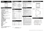
advertisement