advertisement

ENSTROM F-28F/280F SERIES MAINTENANCE MANUAL
Revision 11, dated Oct 25/19, applies to the Enstrom F-28F/280F Series Maintenance Manual,
1985 Edition/1990 2 nd Edition. Place this cover sheet behind the “Record of Revisions” card after removing and inserting the pages listed below.
Remove Pages Insert Pages iii through x xiii through xiv
MM-1-3 through MM-1-4
MM-2-11 through MM-2-20
MM-4-3 through MM-4-4
MM-4-9 through MM-4-12
MM-4-21 through MM-4-22
MM-4-31 through MM-4-32
MM-4-47 through MM-4-48
MM-4-51 through MM-4-56
MM-4-65 through MM-4-66
MM-4-77 through MM-4-78
MM-6-1 through MM-6-8
MM-8-35 through MM-8-36
MM-9-1 through MM-9-48
MM-10-1 through MM-10-50
MM-12-1 through MM-12-71
None
MM-13-31 through MM-13-32
MM-13-35 through MM-13-38
MM-13-49 through MM-13-50
MM-13-67 through MM-13-72
MM-13-93 through MM-13-100
MM-21-15 through MM- 21-16
None
MM-24-7 through MM-24-8 iii through x xiii through xiv
MM-1-3 through MM-1-4
MM-2-11 through MM-2-20
MM-4-3 through MM-4-4
MM-4-9 through MM-4-12
MM-4-21 through MM-4-22
MM-4-31 through MM-4-32
MM-4-47 through MM-4-48
MM-4-51 through MM-4-56
MM-4-65 through MM-4-66
MM-4-77 through MM-4-78
MM-6-0.1 through MM-6-8
MM-8-35 through MM-8-36
MM-9-1 through MM-9-48
MM-10-1 through MM-10-68
MM-12-1 through MM-12-80
MM-13-0.1 through MM-13-0.2
MM-13-31 through MM-13-32
MM-13-35 through MM-13-38
MM-13-49 through MM-13-50
MM-13-67 through MM-13-72
MM-13-93 through MM-13-100
MM-21-15 through MM-21-16
MM-24-0.1 through MM-24-0.2
MM-24-7 through MM-24-10
........................................................................... End of List ...........................................................................
INTENTIONALLY LEFT BLANK
ENSTROM F-28F/280F SERIES MAINTENANCE MANUAL
TABLE OF CONTENTS
Section 1 – Introduction
Table of Contents ...................................................................................... MM-1-1
1-3.
1-4.
1-5.
1-6.
Maintenance Manual Supplements ........................................................... MM-1-3
Maintenance Manual Changes and Revisions .......................................... MM-1-3
Service Document Publications ................................................................ MM-1-4
Application of Warnings, Cautions, and Notes .......................................... MM-1-5
Section 2 – General Information
Table of Contents ...................................................................................... MM-2-1
2-1. General MM-2-3
2-11.
2-12.
Rotor MM-2-10 tail Rotor Assembly ................................................................................. MM-2-10
Operating Limitations and Restrictions ................................................... MM-2-10
2-17. Consumable Parts List ............................................................................ MM-2-20
Section 3 – Airworthiness Limitations
Log of Revisions ........................................................................................ MM-3-2
Table of Contents ...................................................................................... MM-3-3
3-2. Mandatory Inspection Items ...................................................................... MM-3-5
Section 4 – Servicing, Recommended Overhauls, Inspections, and General Maintenance
Table of Contents ...................................................................................... MM-4-1
4-6. Engine Oil System ................................................................................... MM-4-26
ENSTROM F-28F/280F SERIES MAINTENANCE MANUAL
4-14. Tail Rotor Transmission .......................................................................... MM-4-30
Servicing ....................................................................... MM-4-32
4-25.
4-27.
4-29.
4-31.
4-35.
4-37.
4-39.
4-41.
4-45.
4-48. Daily MM-4-40
4-49.
4-50.
4-51.
4-52.
Periodic Inspection Checklists ................................................................ MM-4-40
50 Hour Inspection Guide .............................................................. MM-4-41
100 Hour/Annual Inspection Guide ................................................ MM-4-42
200 Hour Inspection Guide ............................................................ MM-4-57
4-53.
4-54.
400 Hour Inspection Guide ............................................................ MM-4-58
Special Scheduled Inspection Guide ............................................. MM-4-59
4-57.
4-58.
Lower Pulley (Jackstrut) Bearing ............................................................ MM-4-34
Main Rotor Blade Grip .......................................................................... MM-4-34.1
Main Rotor Flapping Bearings ................................................................. MM-4-36
Tail Rotor Pitch Control Bearing .............................................................. MM-4-36
Lubrication, Method
Upper Pulley (Jackstrut) Bearing ............................................................ MM-4-37
Collective Guidetube Bearing .................................................................. MM-4-37
Cyclic Swashplate Bearing ...................................................................... MM-4-37
Idler Pulley Bearings ............................................................................... MM-4-38
Lubrication, Method
Recommended Overhaul Cycles ............................................................ MM-4-39
Main Rotor Blade Strike/Sudden Stoppage (Minor) ....................... MM-4-60
Main Rotor Blade Strike/Sudden Stoppage (Major) ....................... MM-4-61
4-59.
4-62.
4-65.
4-67.
ENSTROM F-28F/280F SERIES MAINTENANCE MANUAL
Tail Rotor Blade Strike/Sudden Stoppage ..................................... MM-4-62
Main or Tail Rotor Transmission Chip Indication ........................... MM-4-64
Maintenance Ground Run ....................................................................... MM-4-66
Ground Handling Wheels ........................................................................ MM-4-68
4-76. Aircraft Preservation and Storage ........................................................... MM-4-73
4-78. Usage
4-79.
4-80.
Storage up to 45 Days ................................................................... MM-4-74
Storage from 45 Days to 6 Months ................................................ MM-4-75
4-81.
4-82.
Storage for longer than 6 Months .................................................. MM-4-75
Preventive Maintenance for Corrosion Control ....................................... MM-4-76
4-84.
4-85.
Scheduled Field Preventive Maintenance Program ................................ MM-4-76
Component Preservation and Storage .................................................... MM-4-77
Section 5 – Weight and Balance
5-1. General MM-5-1
5-2.
5-3.
Approved Center of Gravity Envelopes ..................................................... MM-5-1
Weighing the Helicopter ............................................................................ MM-5-3
Section 6 – Electrical System
6-9.
6-10.
6-13.
6-14.
Clutch Disengage Warning Light ............................................................. MM-6-16
Manifold Pressure Overboost Caution Light ........................................... MM-6-16
Ammeter – Charging System .................................................................. MM-6-18
Instrument Cluster Troubleshooting ........................................................ MM-6-19
ENSTROM F-28F/280F SERIES MAINTENANCE MANUAL
Section 7 – Instruments
7-4.
7-5.
7-6.
7-7.
7-8.
7-10.
7-11.
7-12.
7-13.
7-14.
7-15.
Engine and Rotor Tachometer .................................................................. MM-7-5
Fuel Quantity Indicator .............................................................................. MM-7-5
Engine Oil Pressure Gauge ...................................................................... MM-7-6
Main Rotor Transmission Temperature Indicator ...................................... MM-7-7
Engine Oil Temperature Indicator ............................................................. MM-7-7
Cylinder Temperature Indicator ................................................................. MM-7-9
Exhaust Gas Temperature Indicator (EGT) .............................................. MM-7-9
Manifold Pressure and Fuel Flow Indicator ............................................. MM-7-11
Outside Air Temperature Indicator .......................................................... MM-7-12
Magnetic Compass (F-28F) .................................................................... MM-7-12
Magnetic Compass (280F) ...................................................................... MM-7-12
7-18.
7-19.
Replacement of Instruments ................................................................... MM-7-13
Inspection of Instruments ........................................................................ MM-7-15
Section 8 – Structures
8-2. Windshields and Windows ........................................................................ MM-8-4
8-3. [Reserved]
8-5. [Reserved]
8-6. [Reserved]
8-7.
8-8.
Seat Belts – Lap Type ............................................................................. MM-8-17
Seat Deck and Bulkheads ....................................................................... MM-8-18
8-12. Tailcone MM-8-42
8-12.1.
8-12.2.
Tubular Tail Rotor Guard ........................................................................ MM-8-44
Tail Rotor Driveshaft Cover ..................................................................... MM-8-45
8-13.
8-14.
8-15.
8-16.
Torque Tube Extension ........................................................................... MM-8-46
Horizontal Stabilizers (F-28F Pre-1986) .................................................. MM-8-48
Horizontal Stabilizers (280F) ................................................................... MM-8-49
Horizontal and Vertical Stabilizers (F-28F Post 1986; 280FX) ................ MM-8-50
Section 9 – Main Rotor
9-4. Universal Block Assembly ....................................................................... MM-9-31
ENSTROM F-28F/280F SERIES MAINTENANCE MANUAL
Section 10 – Tail Rotor
10-1. Tail Rotor Assembly ................................................................................ MM-10-3
10-3.
10-4.
10-5.
10-6.
Tracking and Dynamic Balance ............................................................ MM-10-27
Tail Rotor Pitch Control Assembly ........................................................ MM-10-37
Tail Rotor Gearbox ................................................................................ MM-10-45
Tail Rotor Driveshaft and Flex Coupling ............................................... MM-10-48
10-7.
10-8.
Tail Rotor Control System ..................................................................... MM-10-60
Tail Rotor Control Cables ...................................................................... MM-10-61
Section 11 – Drive Belt System
11-1. Clutch Control Rigging ............................................................................ MM-11-1
11-3.
11-4.
Clutch Control Lever ............................................................................... MM-11-8
Jackstrut and Pulley Assembly ............................................................... MM-11-9
11-7.
11-8.
11-9.
Overrunning Clutch and Pulley Assembly ............................................. MM-11-26
Idler Pulley – Troubleshooting ............................................................... MM-11-36
Belt Tension Assembly .......................................................................... MM-11-53
Section 12 – Flight Controls
12-1.
12-2.
12-3.
12-4.
12-5.
12-6.
12-7.
12-8.
12-9.
12-10.
12-11.
12-12.
Troubleshooting the Articulated Rotor System ........................................ MM-12-3
Main Rotor Blade Tracking ...................................................................... MM-12-5
Collective Pitch Control Stick ................................................................ MM-12-19
Collective Trim System ......................................................................... MM-12-22
Cyclic Pitch Control Stick ...................................................................... MM-12-27
Lateral and Longitudinal Trim Actuators ............................................... MM-12-28
Flight Control Rigging ............................................................................ MM-12-34
Cyclic Azimuth Check ........................................................................... MM-12-42
Cyclic Trim Springs Rigging Procedure ................................................ MM-12-44
Lower Swashplate Assembly ................................................................ MM-12-46
Upper Swashplate Assembly ................................................................ MM-12-58
Main Rotor Push Pull Rods ................................................................... MM-12-70
Section 13 – Powerplant and Associated Systems
13-1. Powerplant (General Information) ........................................................... MM-13-1
13-3.
13-4.
Engine Exhaust System ........................................................................ MM-13-19
Fuel Injection System ............................................................................ MM-13-23
13-6.
ENSTROM F-28F/280F SERIES MAINTENANCE MANUAL
Turbocharger Static Air Fuel Nozzle Pressure System ......................... MM-13-49
Section 14 – Utility Systems
MAINTENANCE MANUAL SUPPLEMENT 280FX & 1986 F-28F – SECTIONS 15 THROUGH 25
Section 15 – Supplemental Procedures
15-2.
15-3.
Table of Contents .................................................................................... MM-15-1
Manual Changes and Revisions ............................................................. MM-15-1
Section 16 – [Reserved]
Section 17 – [Reserved]
Section 18 – Powerplant
Section 19 – Main Rotor Transmission
19-2. Main Rotor Gearbox Chip Detector ......................................................... MM-19-1
Section 20 – Belt Drive System
Section 21 – Electrical Systems and Components
21-2. Combined Anticollision and Navigation Lights ........................................ MM-21-1
21-4. Anticollision and Navigation Light and Annunciator Panel
21-5.
21-6.
Lamp/Assembly Replacement Guide Chart ............................................ MM-21-8
Ampere Load Conditions ......................................................................... MM-21-8
21-7. Hi/Lo Rotor RPM Warning System ........................................................ MM-21-11
21-8. Schematic MM-21-14
ENSTROM F-28F/280F SERIES MAINTENANCE MANUAL
Illuminated Collective Switch Panel ............................................. MM-21-33
Illuminated Switch and Circuit Breaker Panel .............................. MM-21-35
Section 22 – [Reserved]
Section 23 – [Reserved]
Section 24 – Instruments
24-4. Programming Alarm Limits ............................................................ MM-24-2
24-7.
24-9.
Outside Air Temperature Indicator (OAT) ............................................... MM-24-7
24-8. Magnetic MM-24-7
Rotor RPM Magnetic Pickup ................................................................... MM-24-8
Section 25 – Tail Rotor Drive Assembly
25-2.
25-3.
Tail Rotor Driveshaft ............................................................................... MM-25-1
Tail Rotor Gearbox Chip Detector ........................................................... MM-25-1
ENSTROM F-28F/280F SERIES MAINTENANCE MANUAL
INTENTIONALLY LEFT BLANK
ENSTROM F-28F/280F SERIES MAINTENANCE MANUAL
REV. NO APPROVED
10 Feb 7/19
Cover ix, xiii, xiv
MM-4-40, MM-4-42
MM-8-0 through MM-8-0.2
MM-8-12 through MM-8-16.2
MM-12-18 through MM-12-22
MM-21-1 through MM-21-4
MM-21-6 through MM-21-8, MM-21-14
MM-21-33 through MM-21-58
MM-24-7 through MM-24-8
Cover iv through vii, ix, xiii
MM-1-3
MM-2-11, MM-2-12
MM-2-14 through MM-2-20
MM-4-3, MM-4-9, MM-4-11
MM-4-22, MM-4-32
MM-4-47, MM-4-51 through MM-4-56
MM-4-65, MM-4-66, MM-4-77, MM-4-78
MM-6-0.1, MM-6-0.2
MM-6-1 through MM-6-8
MM-8-36
MM-9-1 through MM-9-48
MM-10-1 through MM-10-68
MM-12-1 through MM-12-80
MM-13-0.1, MM-13-0.2, MM-13-31
MM-13-35, MM-13-37, MM-13-49
MM-13-67 through MM-13-71
MM-13-93 through MM-13-100
MM-21-15, MM-21-16
MM-24-0.1, MM-24-0.2
MM-24-8 through MM-24-10
N/A N/A
N/A N/A
ENSTROM F-28F/280F SERIES MAINTENANCE MANUAL
INTENTIONALLY LEFT BLANK
ENSTROM F-28F/280F SERIES MAINTENANCE MANUAL
SECTION 1
INTRODUCTION
1-1. Maintenance Manual Arrangement
The maintenance manual sections divide the aircraft into major systems and related subsystems to provide maintenance procedures required for proper system function and optimum component service life. Each section details the following maintenance functions for the associated subsystems and components, if applicable:
Troubleshooting
Adjustment/Rigging
Removal
Disassembly
Inspections (other than Periodic Inspections)
Repair
Assembly
Installation
The maintenance data presented in this manual is applicable to all F-28F, 280F, and 280FX model Enstrom helicopters with standard equipment. Optional equipment maintenance procedures are included in the F-28F/280F Series Maintenance Manual for common optional equipment that is installed before aircraft delivery (This does not include avionics installations).
1-3. Maintenance Manual Supplements
Maintenance procedures for optional equipment may be provided in maintenance manual supplements. These supplements are part of the F-28F/280F Series Maintenance Manual when an aircraft is equipped with optional equipment which requires a maintenance manual supplement. The following optional equipment supplements are applicable to the F-
28F/280F Series Maintenance Manual.
Supplement 1: Avionic Systems, Revision 8, Dated: Jan 15/19.
1-4. Maintenance Manual Changes and Revisions
Subsequent to the publication of the initial issue of the Enstrom F-28F/280F Series
Maintenance Manual, changes in aircraft equipment, support concepts and procedures, as well as information developed by experience, may affect the contents of the manual. To ensure that coverage in the manual continues to reflect such changes, revised information is released by one of the following methods:
(1) Revision - A revision alters portions of the manual by replacement, addition, and/or deletion of pages. A revision cover page lists the page(s) to be removed and/or inserted.
ENSTROM F-28F/280F SERIES MAINTENANCE MANUAL
(2) Reissue - Where large numbers of changes are involved, a complete reissue of the manual is warranted. Preceding issues of the manual then become obsolete and should be discarded.
1-5. Service Document Publications
(1) Service Directive Bulletins – Used to direct the owner/operator and/or maintenance personnel to make mandatory changes, improvements, or inspections to the aircraft applicable to the entire fleet or a segment of the fleet that are typically safety/airworthiness related. The information provided in the Service Directive
Bulletins will be incorporated in the maintenance manual as needed at a later date. At the time of incorporation, the Service Directive Bulletin is superseded by the maintenance manual, and accomplishment or sign-off of the Service Directive Bulletin in the maintenance records book is no longer required. A detailed entry should be made in the maintenance records to indicate that the Service Directive Bulletin is superseded by the maintenance manual.
(2) Service Information Letters – Used to transmit information, recommendations, and general service instructions to the aircraft owner/operator and/or maintenance personnel applicable to the entire fleet or a segment of the fleet. The information provided in the Service Information Letters will be incorporated into the maintenance manual as needed at a later date.
(3) Service Instructions – Used to provide the owner/operator and/or maintenance personnel with information that is applicable to specific aircraft and does not meet the criteria of a Service Information Letter or Service Directive Bulletin. Service
Instructions will not be distributed to the entire fleet.
Service Information Letters and Service Directive Bulletins incorporated into the maintenance manual are logged in the Service Information Letter Index or the Service
Directive Bulletin Index (as appropriate) located on the Enstrom Helicopter website: www.enstromhelicopter.com (follow the applicable link under the Tech Publications section of the Technical Support page). Each index numerically lists all Service Information Letters and Service Directive Bulletins, respectively, and identifies those which have been incorporated into the maintenance manual. All Service Information Letters and Service
Directive Bulletins are also located under the Tech Publications section of the website.
Enstrom distributes maintenance manual reissues and revisions in hardcopy form via mail to owners and operators who are registered with Enstrom. Notice of recently released
Service Information Letters and Service Directive Bulletins is provided via a postcard mailing. Registration to receive publication mailings can be coordinated through Enstrom
Product Support.
ENSTROM F-28F/280F SERIES MAINTENANCE MANUAL
2-14. Vendor Information
The following components listed in Table 2-2 are to be maintained I/A/W the manufacturer's instructions to ensure the continued airworthiness of the aircraft. The owner/operator is responsible for ensuring that current maintenance publications are available to ensure continued airworthiness of the aircraft.
Table 2-2. Vendor Contact Information
Manufacturer*
Engine M/N
Textron-Lycoming
625 Oliver Street
Williamsport, PA 17701
(570) 327-7049 www.lycoming.com
Magneto SYS P/N 66E21585-70
Alternator
Fuel Pump
P/N 10-682605-13
P/N 32C19553 (24V)
P/N ALX-8521LS (12V)
P/N ALU-8521LS (24V)
P/N 62D26035
Hartzell Engine Technologies
2900 Selma Highway
Montgomery, AL 36116
(877) 359-5355 www.hartzell.aero
Starter Vibrator
Fuel Servo
Fuel Boost
Pump
Scavenge Oil
Pump
Starter
EGT Indicator
Graphic Engine
Monitor
P/N 600700-0000
P/N 10-382780-123
(12V)
P/N 10-400608-243
(24V)
M/N RSA-5AB1
P/N 2524858-5
P/N A-10019-D (12V)
P/N A-10019-E (24V)
P/N 101678-0002
P/N 149-12HT (12V)
P/N 149-24HT (24V)
P/N RG24-11M (24V)
P/N 45817
M/N GEM 603
M/N GEM 610
M/N EDM-700
Teledyne Continental Motors
2039 Broad Street
Mobile, AL 36615
(630) 513-9599 www.aviall.com
Precision Airmotive Corporation
14800 40th Avenue, North East
Marysville, WA. 98271
Weldon Pump
640 Golden Oak Parkway
Oakwood Village, Ohio 44146
Kelly Aerospace Power Systems
1404 E. South Blvd.
Montgomery, AL 36116
Sky-Tec
350 Howard Clemmons Road
Granbury, TX 78230
(360) 651-8282 www.precisionairmotive.com
(440) 232-2282 www.weldonpumps.com
(877) 359-5355 www.hartzell.aero
(877) 359-5355 www.hartzell.aero
(800)757-0303 www.concordebattery.com
2009 San Bernardino Road
West Covina, CA 91790
Alcor
300 Breesport
San Antonio, TX 78216
Insight Instrument Corporation
Box 194
Buffalo, NY 14205-0194
J. P. Instruments Inc.
P.O. Box 7033
Huntington Beach, CA 92646
(800) 354-7233 www.alcorinc.com
(905) 871-0733 www.insightinstruments.com
(800) 345-4574 www.jpinstruments.com
ENSTROM F-28F/280F SERIES MAINTENANCE MANUAL
Table 2-2. Vendor Contact Information
Tension-Torson
(TT) Straps
P/N AA-ECD-084-280
(STC SR03465CH)
Manufacturer*
Airwolf Aerospace LLC
15369 Madison Rd.
Middlefield, OH 44062-8404
(440) 632-1687
(440) 632-1685 Fax www.airwolfaerospace.com [email protected]
* The manufacturer of the component may differ depending on the time the aircraft was manufactured or overhauled. Refer to the manufacturer’s data plate affixed to the component for accurate part number information.
ENSTROM F-28F/280F SERIES MAINTENANCE MANUAL
2-15. Special Tools
The special tools listed in Table 2-2 are used for removal, installation, and overhaul of components used on the F-28F/280F series aircraft:
NOTE
The special tools listed in Table 2-2 are available through Enstrom’s Tool Rental
Program. Contact Enstrom Helicopter Product Support for details.
Table 2-3. Special Tools
Part Number
T-0003
T-0005
T-0009
T-0011
T-0013
T-0014
T-0016
T-0017
T-0022
T-0026
T-0027
T-0029-SET
T-0035
T-0036
T-0044
T-0045-1
T-0048
T-0051-3
T-0054
T-0056-3
T-0057
T-0068-3
T-0078
T-0079-1
Nomenclature
Main Rotor Lead/Lag Lower Nut Tool
Damper Rod End Removal Tool
Main Rotor Blade Bolt Guide Bullet
Main Rotor Hoist Sling
Main Rotor Lamiflex Nut Socket
Needle Point Grease Adapter
Lower Swashplate Gimbal Tool
Transmission Hoist Eye
Collective Spring Capsule Retainer Tool
Main Rotor Blade Tab Bending Tool
Main Rotor Blade Tab Angle Tool
Idler Assembly/Disassembly Tool
Oleo Disassembly Tool
Blade Grip Seal Installation Tool
Pulley Alignment Tool
Lower Swashplate Dogleg Puller
Main Rotor Mast Nut Tool
Main Rotor Flapping Nut Tool
Swashplate Dogleg Alignment Tool
Tail Rotor Thrust Bearing Retention Nut Tool
Damper Bleeding Fixture
Tail Rotor Transmission Output Shaft Runout Tools
Engine Adapter Installation Tool
Bearing Swagging Tool
ENSTROM F-28F/280F SERIES MAINTENANCE MANUAL
Table 2-3. Special Tools
Part Number
T-0080
T-0086
T-0087-15
T-0088
T-0092-5
Nomenclature
Tail Rotor Rigging Tool
Upper Guidetube Nut Tool
Tail Rotor Assembly Static Balance Mandrel
Tail Rotor Driveshaft Alignment Tool
Taper Pin Removal Tool
T-0100-1
T-0102-1-SET
T-0104-1
T-0111-SET
T-0121-1
T-0127
T-0133-1
T-0134
T-0135-1-SET
T-0140
T-0151-1
T-0152
T-0156
T-0160-1
T-0168-1
T-0169-1
Swashplate DU Bushing Removal Tool
Guidetube Disassembly Tool
Swashplate Bushing Installation Tool
Correlator Rigging Tool
Tail Rotor Static Balance Stand
Magnetic Pickup Bracket
Pulley Restraint Tool Assembly
Plate Assembly (Lower Swashplate Assembly)
Main Rotor Transmission Pinion Crows Foot
Tail Rotor Rigging Tool
Universal Block Bearing Tool Set (Grease Lubricated)
Tail Rotor Balance Tool (Photo Cell Bracket)
Oil Filler Tube Adapter Wrench
Damper Ring Seal Installation Tools
Tail Rotor Assembly Holder
Oleo Disassembly Tool
T-0179
T-0197-7
T-0198-11
T-0204
Magneto Spring Installation Tool
MR Hub Nut Torque Multiplier Wrench
Enabler, Oil Drain MRGB
Fan Shroud Alignment Tool
ENSTROM F-28F/280F SERIES MAINTENANCE MANUAL
Part Number
T-1575
T-1709
Table 2-3. Special Tools
Nomenclature
Swashplate Centering Tool
Guidetube Bearing Collar Tool
*
T-1775
T-1794
T-2893
T-2896-1
*
*
*
ATP761
Cyclic Centering Rigging Tool
Weight and Balance Datum Tool
Tail Rotor Needle Teeter Bearing Removal/Installation Tool Kit
Damper Bleeding/Servicing Tool (2 Required)
Main Rotor Transmission Stand
Main Rotor Hub Stand
Sprag Clutch Purge Tool
Digital Mast Torque Multiplier
Contact the Enstrom Helicopter Product Support for assistance in obtaining these tools.
ENSTROM F-28F/280F SERIES MAINTENANCE MANUAL
2-16. Torque Data
Unless specified in Table 2-4 and/or in this manual’s maintenance procedures or as called out in the component manufacturer’s specifications, all hardware should be torqued to standard torque values listed in Tables 2-5 through 2-12.
Table 2-4. Special Torque Values
5.
6.
7.
8.
1.
2.
3.
4.
Main rotor mast nut
Main rotor transmission pinion nut
Main rotor blade attachment nuts
Main rotor blade drag link nuts
Main rotor damper pivot nut
Main rotor hub U-block lower nut
Main rotor hub U-block upper nut
Lamiflex bearing retention nut
9. Upper swashplate guidetube nuts
10. Engine mount nut
11. Tailcone attachment bolts
12. Tail rotor assembly retention bolt
13. Tail rotor blade grip nuts 1
14. Tail rotor thrust bearing retention nut
15. Lower engine pulley to crankshaft bolts
16. Pitch change bellcranks
a. Push/pull rod bolt
b. Push/pull rod bolt with floating bushing
17. Landing gear pivot points (all)
18. Landing gear oleo pivots points (all)
19. Tail rotor driveshaft taper pins
20. Dogleg nut
21. Dogleg to swashplate nut
22. Idler yoke/shaft jam nut
23. Fuel pump and fuel injector attach nuts
24. Main Rotor Transmission Magnetic Pick-up
1 Foot-Pound (ft-lb) = 1.3558 Newton Meter (Nm)
1 Inch-Pound (in-lb) = 0.113 Newton Meter (Nm)
1 Nm = 0.7376 ft-lb
1 Nm = 8.851 in-lb
1 Torque for oversize bolts: 140 in-lb/15.9 Nm maximum.
2 Refer to paragraph 8-9.D.5.
400 ft-lb/542.3 Nm
250 ft-lb/339 Nm
50 ft-lb/68.2 Nm
140 in-lb/15.9 Nm
190 in-lb/21.6 Nm
50 ft-lb/67.8 Nm
20 ft-lb/27.1 Nm
12-15 in-lb/1.4-1.7 Nm
240 in-lb/27.1 Nm
460-500 in-lb/52-56.5 Nm
240 in-lb/27.3 Nm
300 in-lb/34.1 Nm
80-90 ft-lb/108.5-122.0 Nm
50 ft-lb/67.8 Nm
40 in-lb/4.5 Nm
75 in-lb/8.5Nm
40-60 in-lb/4.5-6.8 Nm
2 lb/0.9 kg drag ( 2 )
25 in-lb/2.8 Nm
130-140 in-lb/14.7-15.9 Nm
40-60 in-lb/4.5-6.8 Nm
40-45 in-lb/4.5-5.1 Nm
204 in-lb/23.1 Nm
60-65 in-lb/6.8-7.3 Nm
ENSTROM F-28F/280F SERIES MAINTENANCE MANUAL
Table 2-5. Torque Values for Nuts and Bolts
CAUTION THE FOLLOWING TORQUE VALUES ARE DERIVED FROM OIL FREE CADMIUM PLATED THREADS.
Thread Size Tension type nuts
MS20365 and AN310
(40,000 psi in bolts)
FINE THREAD SERIES
TORQUE LIMITS RECOMMENDED FOR INSTAL-
LATION (BOLTS LOADED PRIMARILY IN SHEAR)
(inch-pounds)
Shear type nuts MS20364 and AN320 (24,000 psi in bolts)
8-36
10-32
1/4-28
5/16-24
3/8-24
7/16-20
1/2-20
9/16-18
5/8-18
3/4-16
7/8-14
1-14
1-1/8-12
1-1/4-12
12-15
20-25
50-70
100-140
160-190
450-500
480-690
800-1000
1100-1300
2300-2500
2500-3000
3700-5500
5000-7000
9000-11,000
7-9
12-15
30-40
60-85
95-110
270-300
290-410
480-600
600-780
1300-1500
1500-1800
2200-3300*
3000-4200*
5400-6600*
MAXIMUM ALLOWABLE TIGHTENING
TORQUE LIMITS
(inch-pounds)
Nuts MS20365 and
AN310 (90,000 psi in bolts)
Nuts MS20364 and
AN320 (54,000 psi in bolts)
20
40
100
225
390
840
1100
1600
2400
5000
7000
10,000
15,000
25,000
COARSE THREAD SERIES
8-32
10-24
1/4-20
5/16-18
3/8-16
7/16-14
1/2-13
12-15
20-25
40-50
80-90
160-185
235-255
400-480
9/16-12
5/8-11
3/4-10
7/8-9
500-700
700-900
1150-1600
2200-3000
7-9
12-15
25-30
48-55
95-100
140-155
240-290
300-420
420-540
700-950
1300-1800
20
35
75
160
275
475
880
1100
1500
2500
4600
The above torque values may be used for all cadmium-plated steel nuts of the fine or coarse thread series which have approximately equal number of threads and equal face bearing areas. * Estimated corresponding values.
12
21
45
100
170
280
520
650
900
1500
2700
12
25
60
140
240
500
660
960
1400
3000
4200
6000
9000
15,000
Table 2-6. Fittings, Tubing
Fitting
Size
-2
-3
-4
-5
-6
-8
-10
-12
Tubing OD
(inches)
1/8
3/16
1/4
5/16
3/8
1/2
5/8
3/4
6061-O & 5052-O Aluminum-
Alloy Tube: Fitting or Nut
Torque (in-lb)
20-30
25-35
50-65
70-90
110-130
230-260
330-360
460-500
Steel Tube:
Fitting or Nut Torque
(in-lb)
75-85
95-105
135-150
170-200
270-300
450-500
650-700
900-1000
ENSTROM F-28F/280F SERIES MAINTENANCE MANUAL
Table 2-7. Fittings, Hose Assemblies
Fitting Size
Flexible Hose or Tube Fittings (excluding nylon pitot static lines)
Measurements based on Hose Inside Diameter or Fitting Size
Tube Size
(inches)
Thread Flex Hose and 6061-T6 Aluminum
Alloy Torque Limits (in-lb)
Steel (Torque Limits
(in-lb)
-3
-4
-5
-6
-8
-10
-12
3/16 3/8-24 30
1/4 7/16-20 70 120 135
5/16 1/2-20 70 120 180
3/8 3/4-16 130 180 270
1/2 3/4-16 300 400 450
5/8 7/8-14 430 550 650
3/4 1-1/6-12 650 800 900
Table 2-7.1. Fittings
1/2 3/4-16 180 230 150
5/8 7/8-14 250 350 200
3/4 1-1/6-12 600
Torque Limits (inch-pounds)
For Gasketed Aluminum or Steel Fittings*
For Jamnuts and Fittings Without
Gaskets* *
Nominal
Tube
O.D.
(inches)
Fitting
Thread
Size
AN924 Nut AN815
1/8 5/16-24
Union AN814 Plug AN6289 Nut Aluminum Steel
Min Max Min Max Min Max Min Max Min Max
25 35 25 35
3/16 3/8-24 50 75 30 40 50 75 65 80 70 90
1/4 7/16-20 55 80 75 100
5/16 1/2-20 75
3/8 9/16-18 100
100
150
90
150
120
200
200
350
200
275
450
250
400
650
240
330
280 400
370 550
450
650
* For use with O-rings and aluminum, asbestos, leather, Teflon, gaskets, or washers.
* * For combinations of materials (either jamnut, fittings, or boss), use the lowest applicable values shown.
ENSTROM F-28F/280F SERIES MAINTENANCE MANUAL
Table 2-8. Steel Fittings Using Jam Nuts or Straight Thread O-Ring Boss
Tube Size
Thread Size
(inches)
Torque Limits (inch-pounds)
Min Max
-02 5/16-24 72 84
-03 3/8-24 95 105
-04 7/16-20 155 180
-05 1/2-20 170 180
-06 9/16-18 275 290
-08 3/4-16 480 515
-10 7/8-14 515 575
Table 2-9. Pitot Static System Nylon Fittings
Nominal Tube
O.D. (inches)
Thread Size
(inches)
Torque Limits (inch-pounds)
Min Max
10
Table 2-10. Pipe Plugs
Thread Size
(inches)
1/16-27 NPT
1/8-27 NPT
1/4-18 NPT
3/8-18 NPT
1/2-14 NPT
3/4-14 NPT
1-11-1/2 NPT
Torque Limits
(inch-pounds)
40 to 44
40 to 44
85 to 94
110 to 121
160 to 176
230 to 252
315 to 347
ENSTROM F-28F/280F SERIES MAINTENANCE MANUAL
Table 2-11. Crush Type Gaskets
NOTE
Turn the part until the sealing surfaces are in contact and then tighten to the angle of turn listed for the appropriate thread size.
Thread Pitch On
Part to be
Tightened
(Threads per Inch)
Angle of Turn
Aluminum Copper
Table 2-12. Prevailing Torque Values for Re-used Self-Locking Nuts
Bolt, or Screw Thread
Size (inches)
Seating Torque
(in-lb ±10%)
Prevailing Torque Max.
On or Off (in-lb)
Prevailing Torque Min.
On or Off (in-lb)
4-40 8 5 0.5
6-32 15 8 1.0
8-32 28 12 1.5
AN3 45 18 2.0
AN4 110 40 3.0
AN5 190 85 5.0
AN6 345 110 9.0
AN7 545 150 12.0
AN8 850 220 16.0
If not listed in Table 2-12, a self-locking nut can be reused as long as a wrench is required to turn it on the bolt.
ENSTROM F-28F/280F SERIES MAINTENANCE MANUAL
INTENTIONALLY LEFT BLANK
ENSTROM F-28F/280F SERIES MAINTENANCE MANUAL
2-17. Consumable Parts List
Table 2-13 lists the consumable parts and lubricants that are normally used during servicing or periodic inspection of the aircraft. The quantities listed reflect normal inspection intervals; however, they may need to be adjusted if adverse operating conditions require more frequent servicing or inspections.
Refer to the Lycoming Operator’s Manual (Document 60297-12) and the Lycoming Parts
Catalog (Document PC-406-2) for the consumable parts required for servicing or periodic inspection of the engine.
NOTE
Enstrom does not stock engine parts for customer service use. Obtain engine parts through Lycoming Engines Distribution Partners. For assistance, refer to the Genuine Parts tab on the Lycoming Products web page to find distributors near you ( www.lycoming.com
).
Table 2-13. Consumable Parts List
Item
50 Hour Service
1. Grease
3. Oil
4. O-ring
Part Number †
MIL-PRF-81322 and MIL-G-
25537
SF96-20
MIL-PRF-23699
NAS1612-2
Quantity
As Required
As Required
As Required
6 EA *
100 Hour Service/Inspection
1.
4. Oil
5. Oil
6. Air Filter Element
Same as 50 hour Requirements
AN900-8 or MS35769-9
AN900-10 or MS35769-11
MIL-PRF-23699
MIL-PRF-2105/API GL-5
BA-15
1 EA
1 EA
1 OZ
7 PTS
1 EA
200 Hour Service/Inspection
1. Same as 100 hour requirements
300 Hour Service/Inspection
1. Same as 100 hour requirements
NOTES:
* Replace on condition
† Verify configuration, part number and quantity with latest revision of illustrated parts catalog, service letters, and service bulletins as required.
ENSTROM F-28F/280F SERIES MAINTENANCE MANUAL
SECTION 4
SERVICING, RECOMMENDED OVERHAULS, INSPECTIONS,
AND GENERAL MAINTENANCE
TABLE OF CONTENTS
Paragraph Description
4-80.
4-81.
4-82.
Page
Storage from 45 Days to 6 Months ................................................ MM-4-75
Storage for Longer than 6 Months ................................................. MM-4-75
Preventive Maintenance for Corrosion Control ................................. MM-4-76
4-84.
4-85.
Scheduled Field Preventive Maintenance Program ........................... MM-4-76
Component Preservation and Storage ................................................ MM-4-77
ENSTROM F-28F/280F SERIES MAINTENANCE MANUAL
INTENTIONALLY LEFT BLANK
ENSTROM F-28F/280F SERIES MAINTENANCE MANUAL
Note 1: Refer to the Figure 4-1 illustrations on pages MM-4-13 through MM-4-24 for the lubrication/servicing locations.
Note 2: Refer to paragraph 4-28 for lubrication procedure.
Note 3: Hand pack the bearing if the bearing housing is not equipped with a grease fitting.
Note 4: Only applies to 28-150050 and 28-150079 series tail rotor assemblies.
Note 5: Service in accordance with manufacturer’s instructions.
Note 6: Also referred to as Upper Swashplate Bearing.
Note 7: Also referred to as Lower Swashplate Bearing.
ENSTROM F-28F/280F SERIES MAINTENANCE MANUAL
Table 4-3. Qualified Domestic Commercial Oils for MIL-PRF-7808
MANUFACTURER MANUFACTURER'S DESIGNATION
Air BP Lubricants, Inc.
American Oil
Castrol, Inc.
Exxon Mobil Corp.
Exxon Mobil Corp.
Stauffer Chemical Co.
BP Turbo Oil 2389
American PQ Lubricant 689
Brayco 880
EXXON ETO 2389
Mobil Avrex S Turbo 256, Mobil RM-201A, Mobil RM-184A
Stauffer Jet 1
Table 4-4. Qualified Domestic Commercial Oils for MIL-PRF-23699
MANUFACTURER MANUFACTURER'S DESIGNATION
Exxon Mobil Corp.
NYCO America
Mobil Jet Oil II
Turbonycoil 600 (TN600)
Anderol Specialty Lubricants Aeroshell/Royco Turbine Oil 500
American Oil and Supply Co. American PQ Lubricant 6700
Castrol, Inc. BRAYCO 89
Hatcol Corp.
Air BP Lubricants, Inc.
Exxon Mobil Corp.
Stauffer Chemical Co.
Caltex Petroleum Corp.
HATCOL 3211
Air BP Turbo Oil 2380
EXXON ETO 2380
Staufer Jet II (Castrol 205)
Caltex RPM Jet Engine Oil 5
Chevron International Oil Co. Chevron Jet Engine Oil 5
Exxon Mobil Corp. Mobil Jet Oil 254 (Generation 3/HTS Oil)
Anderol Specialty Lubricants Royco 560 (Generation 3/HTS Oil)
Shell Oil Company Aeroshell Turbine Oil 560 (Generation 3/HTS Oil)
ENSTROM F-28F/280F SERIES MAINTENANCE MANUAL
Table 4-5. Qualified Domestic Commercial Oils for SAE-J2360/API GL-5/MIL-PRF-2105
MANUFACTURER MANUFACTURER'S DESIGNATION
Exxon Mobil Corp.
Shell Oil Company
Exxon
Esso
Mobil 1 Synthetic Gear Lubricant LS 75W-90
Mobil Delvac 1 1 Synthetic Gear Oil 75W-90
Mobilube HD LS 80W-90
Mobilube HD Plus 80W-90
Shell Helix Racing Gear Oil 75W-90
Exxon Gear Oil GX 80W-90
Exxon Synthetic Gear Oil (SGO) 75W-90
Esso Gear Oil GX 75W-90
Esso Gear Oil GX Extra 75W-90
Castrol Syntrax Limited Slip 75W-90 (Syntec Gear Oil) BP Lubricants USA, Inc.
Table 4-6. Qualified Domestic Commercial Greases for MIL-G-25537
MANUFACTURER MANUFACTURER'S DESIGNATION
Anderol Specialty Lubricants Royco 37
Shell Oil Company Aeroshell Grease 14
Table 4-7. Qualified Domestic Commercial Greases for MIL-PRF-81322
MANUFACTURER MANUFACTURER'S DESIGNATION
Anderol Specialty Lubricants Royco 22CF
Aeroshell Grease 22CF
Air BP Lubricants Aeroplex 622
Arpol Petroleum Co. ARPOLUBE 81322
Exxon Mobil Corp.
Castrol, Inc.
Shell Oil Company
Mobilgrease 28
Braycote 622
Aeroshell 22, 22CF
1 Mobil Delvac 1 75W-90 supersedes Mobil Delvac 75W-90 and Mobil SHC 75W-90.
ENSTROM F-28F/280F SERIES MAINTENANCE MANUAL
Table 4-8. Qualified Domestic Commercial Greases for MIL-PRF-23827
MANUFACTURER MANUFACTURER'S DESIGNATION
NYCO America Nyco Grease GN10
Anderol Specialty Lubricants Royco 27
Exxon Mobil Corp.
Exxon Mobil Corp.
Beacon 325
Mobilgrease 27
Petronomics Manufacturing
Group
Shell Oil Company
Petronomics Plus M-P Aircraft Grease
Arpol Petroleum Co.
Castrol Industrial North
America, Inc.
Aeroshell Grease 33
Aeroshell Grease 7
Arpolube 23827
Castrol Aeroplex AI
ENSTROM F-28F/280F SERIES MAINTENANCE MANUAL
31.
32.
33.
View O
Collective Guidetube Bearing Grease Fitting
Cyclic Swashplate Bearing Grease Fitting
Cyclic Swashplate Control Rod Pivots
Figure 4-1. Servicing Locations
Sheet 9 of 12
ENSTROM F-28F/280F SERIES MAINTENANCE MANUAL
34.
35.
36.
37.
38.
View P
Pitch Change Bellcrank Pivot Bearings (3 places)
Pitch Change Bellcrank Inboard Pivot Points (3 places)
Main Rotor Lead/Lag Bearings (3 places)
Main Rotor Feathering Bearings (6 places)
Main Rotor Damper Service Plugs
39.
40.
View Q
Main Rotor Lead/Lag Bearings (3 places)
Main Rotor Flapping Bearings (9 places)
Figure 4-1. Servicing Locations
Sheet 10 of 12
ENSTROM F-28F/280F SERIES MAINTENANCE MANUAL
4-16. Draining – Tail Rotor Transmission
A. If equipped with a chip detector, remove the chip detector from the quick disconnect receptacle.
B. Place a suitable container under the receptacle/magnetic plug.
C. Remove the quick disconnect receptacle/magnetic plug and drain the transmission.
D. When the transmission is drained, replace the crush washer and reinstall the magnetic plug/chip detector. Tighten the magnetic plug/chip detector until the turning surfaces are in contact, then tighten an additional 135° (not to exceed 35 in-lb/4 Nm). Lockwire the receptacle/magnetic plug to the sight glass and the filler plug after the transmission has been serviced.
E. If equipped with a chip detector, reinstall the chip detector.
4-16.1 Flushing – Tail Rotor Transmission
A. Drain the oil (paragraph 4-16, steps A through C only).
B. Remove the filler plug, sight glass, and top visual inspection plug (if not already removed) from the gearbox.
C. Inspect the gears closely for cracked or missing teeth and the gearbox for damage.
D. Use a syphon sprayer with kerosene, mineral spirits, or equivalent oil-based solvent to spray down the interior of the gearbox and flush any debris out of the gearbox. Direct aim the sprayer around the inside of the gearbox to flush the input and output bearings, while rotating the gearbox.
E. Loosely install the bottom drain plug, sight glass, and fill plug.
F. Add one-half quart of the gear lube that is currently used in the gearbox (Table 4-1).
G. Rotate the gears at least ten times to circulate the oil.
H. Place a container covered with a clean, white cloth or filter under the drain plug.
Remove the drain plug and drain the oil into the container while rotating the gears. Allow the gearbox to drain completely.
I. Inspect the cloth for contamination. If there is contamination, repeat steps D through I using a new cloth or filter each time the gearbox is drained. Proceed to step J if there is no contamination.
J. Replace the crush washer and reinstall the top visual inspection plug. Tighten until the turning surfaces are in contact, then tighten an additional 90°. Lockwire the plug to the pivot bushing (.032).
K. Replace the crush washer and reinstall the bottom magnetic plug/chip detector.
Tighten until the turning surfaces are in contact, then tighten an additional 135° (not to exceed
35 in-lb/4 Nm).
L. Service the gearbox (para. 4-15).
ENSTROM F-28F/280F SERIES MAINTENANCE MANUAL
4-17. Main Rotor Dampers (Figure 4-5, View P)
4-18. Servicing (Bleeding) – Main Rotor Dampers
NOTES
Refer to Table 4-1 for system capacity and approved oil.
The dampers may be serviced while installed on or removed from the aircraft.
A. Servicing the dampers with tools T-2896 (Figure 4-1, View P, right):
(1) Fill the tools approximately half full with L-45 Silicone Oil.
(2) Remove the reservoir plugs and replace the O-rings as required.
(3) Install the tools into the reservoir.
(4) Depress one plunger only until the bubbles stop entering the other syringe. Then cycle the second syringe until the plunger is almost at the bottom.
(5) Slowly cycle the plungers until all the air bubbles are purged from the damper.
(6) Remove the tool from the “lower” port of the reservoir and install the plug.
(7) Remove the tool from the “upper” port of the reservoir and completely fill the reservoir before installing the plug.
(8) Tighten and lockwire (.025) the plugs.
B. Alternate method of servicing the dampers:
NOTE
Do not cycle the blades back and forth during this procedure as it will mix any air that is in the reservoirs and distribute it through the damper.
(1) cycle the three blades in one direction until the damper piston is fully compressed.
(2) Remove all of the caps from the reservoirs and fill the reservoirs to the top of the port. Reinstall the caps.
(3) cycle the three blades in the other direction until the damper piston is fully extended.
(4) Remove all of the caps from the reservoirs and fill the reservoirs to the top of the port. Reinstall the caps.
(5) Perform this procedure three times or until the reservoirs show full when the caps are removed.
ENSTROM F-28F/280F SERIES MAINTENANCE MANUAL
100 HOUR/ANNUAL INSPECTION GUIDE
E. Ground Handling Wheels:
1) Inspect the ground handling wheels and brackets for condition and security of installation.
2) Inspect the tires for condition and proper inflation.
_________
3) Inspect the quick disconnect locking pins for condition.
_________
_________
A. Belt Engagement (Clutch) Assembly:
1) Inspect the spring capsule for proper extension with the belt clutch engaged, worn bushings in the side plates, condition, and security of installation.
_________
2) Inspect clutch capsule adapter and bushing for wear. Replace Bushing
(P/N 07-DU-08 as required.
NOTE: Lube springs and capsule in accordance with Paragraph G, (10) on
Page MM-11-65.
_________
3) Inspect the side plates for wear in the slot, condition and security of installation.
4) Inspect the over-center microswitch for condition and proper operation.
5) Inspect the engagement bellcrank for loose or worn bushings, condition, and security of installation.
6) Inspect the clutch engagement cable for condition and security of installation.
_________
_________
_________
B. Idler Pulley Assembly:
1) Inspect the idler pulley support bracket for worn bushings, cracks, condition, and security of installation.
2) Inspect the idler pulley yoke and shaft for cracks, worn rod end bearing, rod end threads (corrosion and corrosion protection condition (SDB 0127)), condition and security of installation.
_________
_________
3) Inspect the idler pulley yoke straps for worn bushings, cracks, condition, and security of installation.
4) Inspect the idler pulley for worn bearings, evidence of the drive belt not tracking properly, condition, and security of installation.
5) Inspect the belt snubber roller for worn bearings, condition, security of installation, and proper alignment/clearance with the drive belt (drive belt engaged).
6) Inspect the idler pulley pylon support strut for condition and security of installation.
_________
_________
_________
_________
ENSTROM F-28F/280F SERIES MAINTENANCE MANUAL
100 HOUR/ANNUAL INSPECTION GUIDE
C. Jackstrut and Lower Pulley Assembly:
1) Inspect the jackstrut for bond separations, condition, and security of installation.
2) Inspect the lower pulley for wear, excessive grease leakage, condition, and security of installation.
_________
_________
1) Inspect the upper pulley wear, condition, and security of installation.
2) Inspect the overrunning clutch for proper servicing, leaks, condition, and security of installation. Service the overrunning clutch I/A/W para. 4-13.
3) Inspect the pinion bearing assembly for evidence of worn or loose bearing, condition, and security of installation.
4) Check pinion bearing nut for proper torque.
_________
_________
_________
_________
_________ 1) Inspect the drive belt for cracks, fraying, missing sections, and I/A/W SIL
0074.
1) Inspect the pylon in the belt drive area for corrosion, cracks, dents, or other damage, and condition of the protective primer/epoxy coating.
7. TAIL CONE ASSEMBLY
_________
1) Inspect the tail cone bulkheads, longerons, stringers, doublers, and fittings for cracks, dents, and loose rivets.
2) Inspect the tail cone for proper installation.
_________
_________
3) Inspect the static ports for obstructions, damage, and security of installation.
_________
B. Horizontal and Vertical Stabilizers:
1) Inspect the horizontal and vertical stabilizers for damage, cracks, loose rivets, and security of installation.
_________
C. Tail Rotor Guard:
1) Inspect the tail rotor guard for damage, loose rivets, and security of installation. _________
ENSTROM F-28F/280F SERIES MAINTENANCE MANUAL
100 HOUR/ANNUAL INSPECTION GUIDE
B. Main Rotor Retention Assemblies:
1) Inspect the flapping stops and pitch horn for condition and security of installation.
2) Inspect the blade grips and drag links for condition and security of installation.
3) Inspect the blade pins for corrosion and condition.
_________
_________
_________
4) Inspect Lamiflex bearings for condition.
_________
1) Inspect the lead/lag stops and lower nuts for condition and security of installation. _________
D. Main Rotor Dampers:
1) Inspect the main rotor dampers for leaks, condition, and security of installation.
2) Inspect the damper rod end bearings for excessive radial wear (.007"/.18 mm max.), inspect for corrosion in the threads (SDB 0127) and thread corrosion protection condition.
_________
_________
E. Main Rotor Hub Center Section:
1) Inspect the hub center section for cracks, nicks, scratches, corrosion, and condition and security of hardware.
_________
2) Inspect the upper and lower spline adapters for fretting.
3) Inspect the torque stripe indicators on the mast nut. If the indicators show loss of torque on the mast nut or are not installed, check the torque on the mast nut (400 ft-lb/542.3 Nm).
_________
_________
F. Pitch Change Bellcranks:
1) Inspect the pitch change bellcranks for condition, excessive wear and bearing operation at pivot points, and security of installation (refer to para.
12-11, D).
_________
G. Pitch Change Links:
1) Inspect the pitch change links for excessive rod end bearing wear, condition and security of installation. _________
H. Upper Control Push-Pull Rods:
1) Inspect the push-pull rods for excessive wear in the upper fitting, looseness of fitting, and evidence of damage.
_________
ENSTROM F-28F/280F SERIES MAINTENANCE MANUAL
100 HOUR/ANNUAL INSPECTION GUIDE
12. SWASHPLATE CONTROL SYSTEM
1) Inspect the lower swashplate assembly for condition and security of installation.
2) Inspect the lower swashplate assembly universal joint for looseness (Refer to para. 12-10, C).
3) Inspect the upper control rod end (dogleg) bearings for excessive wear and security of installation (Refer to para. 12-11, D).
4) Inspect the longitudinal and lateral control rod ends for excessive wear, corrosion, and security of installation (Refer to para. 12-12, B and SDB
0096, latest revision).
5) Inspect the cyclic bearing for excessive wear.
B. Collective Guide Tube Assembly:
1) Inspect the collective guide tube assembly for condition and security of installation.
2) Inspect the guide tube DU washers for radial wear.
3) Inspect the collective bearing for excessive wear.
4) Inspect the collective walking beam for cracks, nicks, scratches, condition, excessive wear at the pivot strap bushings, and security of installation.
_________
_________
_________
_________
_________
_________
_________
_________
_________
13. CABIN SECTION
1) Inspect the cabin doors for proper operation, condition, and security of installation.
2) Inspect the windshield(s), cabin windows, and door windows for cracks, crazing, and other damage.
_________
_________
3) Inspect the pitot tube for obstructions, damage, and security of installation.
4) Inspect the position light assemblies for condition and security of installation (If applicable).
_________
_________
1) Inspect the cabin interior for corrosion, damage, and presence/legibility of required and other placards.
2) Inspect the carpeting/upholstery and trim for condition and security of installation.
3) Inspect the seat cushions and seat deck for damage and security of installation.
_________
_________
_________
ENSTROM F-28F/280F SERIES MAINTENANCE MANUAL
100 HOUR/ANNUAL INSPECTION GUIDE
4) Inspect the safety belts and shoulder harnesses for condition, proper operation, and security of attachment.
5) Inspect the fire extinguisher for date of the last inspection and security of installation.
1) Inspect the instrument console/panel and shrouds/covers for condition, security of installation, presence/legibility of required placards and other placards.
2) Inspect the instruments and other equipment for condition and security of installation.
_________
_________
_________
_________
1) Inspect the seat structure and bulkheads for corrosion, loose rivets, and other damage.
E. Cabin Heating System:
1) Inspect the heating system ducts and outlets for obstructions, condition, and security of installation.
2) Inspect the heater controls for proper operation, condition, and security of installation.
_________
_________
_________
14. FLIGHT CONTROLS
A. Cyclic Flight Controls:
1) Inspect the cyclic flight controls for freedom of operation and proper range of travel (refer to para. 12-7, B).
2) Inspect the cyclic sticks, control rods, and bellcranks for condition, excessively worn rod end bearings/bushings, and security of installation.
3) Inspect the upper cabin bellcrank mounts for cracks, condition, and security of installation (SDB 0126).
4) Inspect the trim motor assemblies and bias springs for condition and security of installation.
_________
_________
_________
_________
B. Collective Flight Controls:
1) Inspect the collective flight controls for freedom of operation and proper range of travel (collective contacts up stop and down stop).
2) Inspect the collective friction for proper operation, condition, and security of installation.
_________
_________
ENSTROM F-28F/280F SERIES MAINTENANCE MANUAL
100 HOUR/ANNUAL INSPECTION GUIDE
3) Inspect the collective sticks, torque tube assembly, control rods and bellcranks for excessively worn rod end bearings/bushings, and security of installation.
4) Inspect the collective spring capsule assembly for proper operation, condition and security of installation.
5) Inspect the correlator system for proper operation, condition, and security of installation.
C. Tail Rotor Controls:
_________
_________
_________
1) Inspect the tail rotor control cables and turnbuckles for wear, corrosion, proper operation, proper cable tension, correct range of travel, and security of installation (refer to para. 10-8, A).
2) Inspect the pulleys and fairleads for wear, proper operation, and security of installation.
3) Inspect the pedal assemblies, control rods, and bellcranks for excessively worn rod end bearings/bushings, condition, and security of installation.
4) Inspect the tail rotor pitch change horn/pitch change link assembly for condition and security of installation (SDB 0125).
_________
_________
_________
_________
15. BATTERY AREA
1) Inspect the battery as required in accordance with the manufacturer's instructions.
B. Battery Tray (Forward or Aft Installation):
_________
1) Inspect the battery tray, hold down hardware, and surrounding area for evidence of electrolyte leakage and other damage.
2) Inspect the battery cables and other electrical components/wiring in the area for corrosion, condition, and security of installation.
3) Inspect the battery vent lines for obstructions, condition, and security of installation.
_________
_________
_________
ENSTROM F-28F/280F SERIES MAINTENANCE MANUAL
100 HOUR/ANNUAL INSPECTION GUIDE
16. ELECTRICAL SYSTEMS
A. Inspect the wiring harness and terminal strips for condition and security of installation.
B. Inspect the external power system for proper operation, condition and security of installation.
C. Inspect the cockpit/instrument lighting for proper operation, condition, and security of installation.
D. Inspect the landing, anti-collision, and position light systems for proper operation, condition, and security of installation.
E. Inspect the caution and warning systems for proper operation, condition, and security of installation.
F. Inspect the cyclic trim system for proper operation, condition, and security of installation.
_________
_________
_________
_________
_________
_________
G. Inspect the fuel boost pump for proper operation.
H. Cycle all switches and circuit breakers and inspect for proper operation, condition, and security of installation.
I. Inspect all other electrical equipment not specifically covered by this checklist for proper operation, condition, and security of installation.
_________
_________
_________
16.1 OPTIONAL EQUIPMENT WITH MAINTENANCE MANUAL SUPPLEMENTS
1) Inspect the applicable Avionic System(s) I/A/W Maintenance Manual
Supplement 1, Paragraph 3-3
_________
ENSTROM F-28F/280F SERIES MAINTENANCE MANUAL
100 HOUR/ANNUAL INSPECTION GUIDE
17. POST INSPECTION
A. Lubrication and Servicing:
1) Ensure all required items have been lubricated and serviced per the maintenance manual lubrication and servicing charts.
B. Correct all discrepancies and install all cowling, access panels, doors, and other items removed for this inspection.
Check engine/post flight requirements in the Textron-Lycoming O, HO,
AIO, HIO, TIO-360 Series Operator’s Manual. Run the aircraft I/A/W the
Enstrom F-28F, 280F, or 280FX Rotorcraft Flight Manual. Check the engine instruments, fuel quantity and flow systems for proper operation.
2) Flight Control Check:
Whenever disassembly of the flight controls, especially the removal of the main rotor hub, has been accomplished, it is recommended that a test flight be performed. See the Enstrom F-28F/280F Series Maintenance Manual for full details.
_________
_________
_________
_________
WARNING
Test flight to be performed by authorized personnel only.
3) Avionics and Flight Instruments: Check operation.
D. Post Operation Check:
1) Inspect the engine compartment for oil and fuel leaks.
E. Enter the inspection compliance in the airframe and engine logbooks as applicable.
F. Perform a maintenance test flight.
WARNING
Test flight to be performed by authorized personnel only.
_________
_________
_________
_________
ENSTROM F-28F/280F SERIES MAINTENANCE MANUAL a. Tail rotor transmission metal particles, flakes, or slivers exceeding .035 inch/.9mm: Contact Enstrom Customer Service Department and discontinue use until further instructions are received from Enstrom Customer Service
Department.
NOTE
Sludge normally will not cause a chip indication by itself. There is normally a small particle, flake, or sliver on the detector also. b. Sludge (a mixture of oil and fine metal particles resulting from normal gear operation): Clean the detector and return the transmission to service.
C. Three main rotor or two tail rotor transmission chip indications occur within 10 flying hours. Perform the following:
NOTE
Check the aircraft inspection records for any annotations about the condition of the main rotor transmission ring and pinion gears or the tail rotor transmission input and output gears.
(1) Drain the oil from the transmission and inspect the ring and pinion gears (main rotor transmission) or the input and output gears (tail rotor transmission) for cracks, excessive pitting, excessive spalling, or "hard wear" lines.
(2) Remove the tail rotor assembly from the tail rotor transmission output shaft and the aft tail rotor drive shaft flex plate assembly. Turn the tail rotor transmission output shaft by hand. If indications of a rough bearing are felt, the transmission must be replaced.
NOTE
If the gearbox is to be returned to Enstrom Service, do not clean the metal from the chip detector.
(3) If none of the above conditions are found, flush and service the transmission
(main rotor, para. 4-13.1; tail rotor, para. 4-16.1), and return to service. If two chip indications occur within the next 10 flying hours, repeat the flush and servicing procedure. If two additional indications occur within the next 10 flying hours, contact Enstrom Helicopter Corporation for further instructions.
4-63. Engine Overboost – Special Instruction
A. Inspect the engine in accordance with the latest revision of Textron-Lycoming Service
Bulletin 592.
ENSTROM F-28F/280F SERIES MAINTENANCE MANUAL
4-64. Engine Overspeed – Special Instruction
A. Inspect the engine in accordance with the latest revision of Textron-Lycoming Service
Bulletin 369.
NOTE
Perform the appropriate main rotor overspeed inspection if required.
4-65. Maintenance Ground Run
(1) Perform a maintenance ground run after conducting a periodic inspection or maintenance action that will require operation of the aircraft to verify satisfactory performance of the aircraft.
(2) The periodic inspection or maintenance action will determine the extent of the post maintenance ground run.
(1) Position lateral and fore/aft trim motors to the neutral position.
(2) Move the cyclic stick around the cyclic stop in the floor. The stick must remain against the stop through the circle. If binding or interference is detected, recheck the basic rigging.
(3) Move the fore/aft trim to full forward position and move the cyclic stick full aft.
Stick should contact the cyclic stop. Reverse the trim motor and stick positions and check that stick contacts the cyclic stop.
(4) Repeat step (3) using the lateral trim motor and moving the stick in the lateral direction.
C. Inspect engine operation for (1500 rpm idle):
(3) Engine compartment for oil or fuel leakage
(5) Mixture control for idle cut-off operation.
ENSTROM F-28F/280F SERIES MAINTENANCE MANUAL
(2) Wash the aircraft with mild soap and fresh water weekly.
NOTE
Use a good quality paste wax.
(3) Wax the aircraft every second week.
B. Aircraft that are operated in tropical or semi-tropical high humidity regions. Use the following procedures:
(1) Wash the aircraft with mild soap and fresh water weekly.
(2) Wax the aircraft every second week.
C. Aircraft that are operated in arid, moderate, or cold regions. Use the following procedures:
NOTE
This procedure may be suspended during cold or winter months if step 3 was accomplished prior to the cold season.
(1) Flush with fresh water weekly.
(2) Wash the aircraft with mild soap and fresh water monthly.
(3) Wax the aircraft every second month.
4-85. Component Preservation and Storage
4-86. Main Rotor Transmission
NOTE
This procedure applies to an uninstalled main rotor transmission.
A. Service the main rotor transmission (para. 4-12), or alternatively, completely fill the transmission. Refer to Table 4-1 for system capacity and approved oils (30 weight engine oil is acceptable for storage).
B. Plug or cap the breather tube.
C. Ensure the fill cap is secured.
D. Place the transmission in storage with the mast upright.
E. Every 90 days, move the transmission to allow oil to flow to all internal surfaces.
ENSTROM F-28F/280F SERIES MAINTENANCE MANUAL
(1) Tip the transmission to horizontal or vertical, as appropriate, approximately 90° from its storage position.
(2) Tip the transmission back to storage position.
F. Turn the pinion approximately three times completely lubricate all moving parts.
G. Prior to returning the main rotor transmission to service:
(1) Remove the breather tube plug or cap, if installed.
(2) Drain the oil (para. 4-13).
(3) Service the main rotor transmission (para. 4-12).
ENSTROM F-28F/280F SERIES MAINTENANCE MANUAL
Paragraph Description
SECTION 6
ELECTRICAL
TABLE OF CONTENTS
Page
B. Troubleshooting – Battery .................................................................. MM-6-2
C. Troubleshooting – Battery Master Power ........................................... MM-6-2
D. Buss Faults Breaker System .............................................................. MM-6-4
ENSTROM F-28F/280F SERIES MAINTENANCE MANUAL
INTENTIONALLY LEFT BLANK
ENSTROM F-28F/280F SERIES MAINTENANCE MANUAL
SECTION 6
ELECTRICAL
The F28F/280F Series electrical system is either a 12 volt or a 28 volt D.C. solid state regulated type. The system consists of one main buss, one generating source and one power storage source. Electric current is distributed via buss bar thru individual trip free circuit breakers. Networks not protected by trip free breakers contain inline fuses. Later
F-28F/280FX helicopters are equipped with a 28 volt D.C. electrical system. Electrical power is supplied by a 24-volt, direct current, 70 ampere alternator and an 11 amp-hour lead acid battery.
Electrical safety devices are provided for buss overcurrent and overvoltage protection.
Aircraft equipped with avionics systems are supplied with radio frequency interference filters.
Refer also to Section 21 for discussion regarding F-28F/280FX electrical system equipment updates.
(1) Always refer to the Electrical System Schematic for system interconnections
(Section 6 or Section 21 as applicable).
(2) Simple, fast, wire checks can be performed by making continuity tests with an ohmmeter. The continuity check is a quick procedure for isolating electrical problems to a specific circuit.
(3) Check for loose hardware or loose connectors at wire terminations.
(4) Check all ground connections for evidence of looseness or corrosion.
(5) Check wire insulation, grommets, and tie wraps for wear or deterioration.
(6) In the event of trouble with A/C lighting (non-LED type), substitute equivalent bulbs (known to operate) from a different location on the A/C to determine whether the problem is lamp or system related. This is especially useful for check strobes and anti-collision lamps.
(7) The following devices should be serviced as recommended the respective manufacturers.
(d) Fuel boost pump motor
ENSTROM F-28F/280F SERIES MAINTENANCE MANUAL
(8) Continuous wire runs (ref. schematic diagram) are typically identified by an assigned wire number, i.e. 24-2, from the aircraft battery positive terminal to the starter relay contacts. In cases where wire runs are interrupted by splices, disconnects, fuses etc., the wire number is also assigned a letter, i.e., wire 49-
1A from buss to F3, and wire number 49-1B from the opposite end of F3 to wire number 49-1C. The A-B designation indicates wire discontinuities. Typically wire numbers (not letters) sequence through electrical devices, such as lamps, motors, and relays, etc.
6-2. BATTERY
The aircraft is equipped with a 12 volt or 24 volt battery as described below. The following specifications apply to the standard aircraft battery:
Amp Hours
Cold Cranking Amperes
Overall Dimensions (in) (mm)
29
390
9.78L x 5.17W x 6.83H
(248L x 131W x 174H)
B. Battery – Troubleshooting
Problem Cause
Battery discharged Loose or corroded terminals
11
160
8.65L x 7.31W x 6.73H
(220L x 186W x 171H)
Required Action
Clean connections, tighten terminal hardware
Installation
NOTE: Refer to Concorde RG Series Component Maintenance Manual, Document No. 5-
0171 for electrical renew test procedure.
C. Battery Master Power – Troubleshooting
Problem
Master switch-on, all electrical systems inoperative
Cause
Dead battery
Master relay faulty (RL1)* (coil or contacts bad)
Required Action
Replace or recharge
Replace master relay
Overcurrent trip breaker “open” or faulty (CB16)*
Inline fuse blown (F18)*
Reset overcurrent breaker or replace breaker if faulty
Replace fuse
Replace breaker Overcurrent breaker faulty
(CB17)*
Current limiter faulty (F9) Replace current limiter
* Applies to early F-28F/280F with buss faults breaker protection system.
ENSTROM F-28F/280F SERIES MAINTENANCE MANUAL
Fig. 6-1A. Alternator (left) and Starter Installation (right)
(shroud removed for clarity)
Fig. 6-1B. Alternator and Starter Installation (Inactive)
Top - Fan shroud side showing alternator mount pivot slide tension bar and drive belt
Bottom - Underside of engine showing alternator mount position and pivot mount bolts
ENSTROM F-28F/280F SERIES MAINTENANCE MANUAL
D. Buss Faults Breaker System
General Description – Early F-28F/280F Series
The battery protection system is designed to remotely sense electrical overloads in the aircraft which cause excessive battery current drain. This system consists of fuse (FIB), overcurrent breaker (CB17) and the “overcurrent trip” breaker (CB16) on the instrument panel. Circuit breaker CB17 (located at the aircraft battery) senses the overload condition, simultaneously trips the dash-mounted overcurrent breaker CB16 and deactivates the master relay. The action removes the battery from the aircraft buss.
Battery power cannot be returned to the aircraft buss unless the “overcurrent trip” dashmounted breaker is first reset. The "overcurrent trip” breaker cannot be reset until the overload condition has been corrected. Repair of this system is limited to replacement of faulty components, and the removal of the overload condition.
Electrical current is distributed via buss bar through individual trip-free circuit breakers.
Networks not protected by trip-free breakers contain inline fuses.
General Description – Later F-28F/280FX
The battery and APU buss are protected by a current limiter (F9) which is located at the aft mounted battery box and is installed between the starter relay and the master switch relay which is located on the electrical panel located just inboard of the airbox.
The remaining circuits are protected by either switch type circuit breakers or trip free push/pull circuit breakers installed on the lower console switch panel or on the lower avionics panel. Secondary circuits are normally protected by fuses located on a panel which is installed on the left side of the lower instrument panel console. On aircraft (F-
28F S/N 833 and subsequent; 280FX S/N 2167) with illuminated panels, all standard equipment (with the exception of the starter stuck relay), is protected by a circuit breaker or switch type circuit breaker (Figure 24-3). Some optional equipment may be protected by an in-line fuse. The starter stuck relay fuse (F25) is an in-line type and is located on the aft side of the battery tray.
6-3. ALTERNATOR
The aircraft alternator is a belt driven type. The alternator output rating is 70 amperes continuous at approximately 12 volts D.C. or 28 volts D.C., depending on the electrical system. Principle components of the alternator are the stator, the rotor, the slip ring end head, the drive end head and the rectifier diodes.
The following list suggests areas to be investigated should alternator performance be suspect:
(1) Brushes – Remove and inspect for condition and seating
(2) Rotor – Test for ground or shorted windings
(3) Rectifier Diodes – Test for open or shorted diodes
(4) Stator – Test for open
(5) Bearings – Check for roughness or excessive clearance.
ENSTROM F-28F/280F SERIES MAINTENANCE MANUAL
(6) Housing cleanliness – End housing should be kept clean by wiping with a cloth dampened in solvent
NOTE: It is recommended that the service manual applicable to your alternator type be consulted for detailed repair procedures.
C. Alternator – Removal
(2) Remove cowling and baggage box.
(3) Remove jackstrut and pulley assembly. (See Section 11-4 for Jackstrut Removal
Procedure).
(4) Remove the fan assembly exposing the alternator.
(5) Cut safety wire on bolt securing alternator belt tension arm and remove bolt. Pivot alternator and remove v-belt from alternator pulley.
(6) Disconnect wires from alternator. Label the wires or note the position of the wire numbers for correct placement on reinstallation.
NOTE : The ground wire is connected to the case of the alternator; not to the AUX terminal.
(7) Remove the two alternator mount bolts and remove alternator.
D. Alternator – Inspection
(1) Inspect the alternator I/A/W the manufacturer’s instructions.
(2) Inspect the alternator mount for corrosion, damage, and security.
(3) Check belt tension slip at 12-14 ft-lbs/16.3-19.0 Nm.
NOTE: It is recommended that the service manual applicable to the alternator type be consulted for detailed repair procedures.
E. Alternator – Installation
CAUTION: Inadvertent engine starting may occur when turning the engine by hand unless precautions are taken. Remove the ignition wires from the spark plugs before manually turning the crank shaft.
NOTE : On new or replacement alternators, remove fan and replace with spacer from removed alternator (Reference SIL 0016).
NOTE : Remove cooling shroud from the aft side of the alternator.
(1) Align alternator with mount bracket and install the two attachment bolts.
NOTE : Tighten mount bolts finger tight allowing alternator to pivot. (Tighten alternator attachment bolts to take out clearance but allow movement for adjusting tension.)
ENSTROM F-28F/280F SERIES MAINTENANCE MANUAL
(2) Install the alternator adjusting arm and tighten the bolts finger tight to allow the alternator to pivot.
(3) Install the starter ring gear support (flywheel) on the crankshaft and secure with two, temporary, ½ x 20 x 1 inch bolts installed in the two positions where there are no crankshaft bushings. (It is acceptable to use a ¾ x 6 inch tubular spacer over two of the 28-13306-1 (AN178H bolts).)
CAUTION: Do not install any shims between the flywheel and the crankshaft flange.
(4) Install the belt over the two pulleys.
(5) Pivot the alternator and adjust the belt tension until the pulley just slips at 12 ftlbs/16.3 Nm. (Set tension to 14 ft-lbs/19.0 Nm for new installations.)
(6) Torque the outboard bolt through the adjustment arm (80-90 in-lb/9.0-10.1 Nm).
(7) Remove the bolts securing the starter ring gear support and pull off the starter ring gear support and the belt.
(8) Torque the inboard adjusting arm bolts (80-90 in-lb/9.0-10.1 Nm) and safety wire both bolts (MS20995C32).
CAUTION: Alternator attachment hardware must not be loose.
(9) Torque the alternator mount bolts (160-190 in-lb/19.1-21.6 Nm) and install the cotter pins.
(10) Install the starter ring gear support on the flywheel.
(11) Install the alternator belt over the alternator pulley and turn the crankshaft by hand while guiding the belt onto the pulley.
CAUTION: Connect the ground wire to case ground. Do not connect it to the
AUX+ terminal.
(12) Connect wires to the alternator as previously marked.
(13) Install and secure the lower access panel on the fan shroud and tighten hardware to standard torque.
(14) Position auxiliary oil cooler in place and secure with four attachment bolts.
(15) Install fan assembly and shims on flywheel.
(16) Install jackstrut and pulley assembly. (See Section 11-4 for jackstrut Installation procedure.)
(17) Inspect all items for security.
(19) Connect battery cables.
ENSTROM F-28F/280F SERIES MAINTENANCE MANUAL
INTENTIONALLY LEFT BLANK
ENSTROM F-28F/280F SERIES MAINTENANCE MANUAL
NOTE : Updates to lighting, caution/warning annunciators, and electrical schematics are provided in Section 21.
Alternator voltage is controlled by a solid state transistor regulator. The regulator is factory set for proper voltage control and should not normally require field adjustment.
Field repair of the regulator is generally not practical and the unit should be replaced in the event of failure.
Symptoms of a faulty regulator include:
(1) Continuous discharge on aircraft ammeter.
(2) Large fluctuations in ammeter needle (needle oscillates from charge to discharge.
(3) Excessive charging indication on ammeter with fully charged or new battery.
(4) Ammeter needle drops to discharge position as additional electrical loads are switched on, such as strobes, landing lights, etc.
(5) Battery frequently requires water indicates overcharging regulator.
NOTE : Solvents and engine cleaning fluid should not be used on the regulator. Cover regulator during engine compartment cleaning.
ENSTROM F-28F/280F SERIES MAINTENANCE MANUAL
NOTE: The piston must be inserted into the cylinder assembly slowly to allow the hydraulic fluid to work through the staggered notches of the rebound rings and the flow passage in the piston assembly.
(k) Install the piston and guide shaft assembly into the cylinder assembly. Slowly push the piston to the base of cylinder assembly (collapsed position).
NOTE: The guide shaft assembly will be torqued in a later step.
(l) Hand tighten the guide shaft assembly (6) to the cylinder assembly (14). Make an index mark from the guide shaft assembly to the cylinder assembly.
(m) Install and secure oleo valve (1). Safety wire (MS20995C32) valve to mount flange of piston shaft.
(n) Loosen the air valve.
(o) Attach one end of a clear plastic hose to the oleo valve and the other end in a container of MIL-PRF-5606.
(p) Open the air valve. Slowly pump the strut in and out until the hose is free of air bubbles when compressing the oleo assembly.
(q) Fully collapse the strut, tighten the air valve, and remove the hose.
(r) Torque the guide assembly using T-0169-1. Using the index mark, torque the guide assembly to the cylinder assembly by turning the index mark on the cylinder assembly approximately ¼ inch past the index mark on the guide assembly.
NOTE: The oleo may be pressurized before or after installation in the helicopter. (If the oleo is not installed, pressurize to 200 psi (1,379 kPa) and check for leaks.)
(s) Connect the nitrogen pressure line to the oleo valve. Set the nitrogen pressure regulator to 400 psi (2,758 kPa). Remove the oleo from the vise and remove tools T-
0035 and T-0169-1.
WARNING: The piston shaft will extend when the oleo valve is opened.
(t) Slowly open the oleo valve and allow the oleo to fill until the piston shaft is fully extended and the oleo pressure has equalized to the regulator pressure. Close the oleo valve.
(u) Close the nitrogen tank valve, set the regulator pressure back to zero, and disconnect the nitrogen pressure line from the oleo valve.
(v) Install the valve cap.
(w) Inspect the oleo for leaks.
ENSTROM F-28F/280F SERIES MAINTENANCE MANUAL
5. Oleo Strut – Installation (see Figure 8-11)
NOTE: Helicopter must be jacked or hoisted with a sling for oleo strut installation.
(a) Lubricate the attachment hardware with LPS 2, ACF 50, or MIL-PRF-81322 grease and install while wet.
(b) Place a light washer (2) on each side of universal link (1) and install between mount ears on oleo strut (2 places). Secure in place using bolt (5), light washers (3) and nut (4) (Figure 8-11). Note there is no washer under the head of the top inboard attachment bolt (P/N 28-17135-11).
(c) Place a light washer (2) on each side of universal link (1) and install the oleo assembly between mount ears on cross tube. Secure in place using bolt (5), heavy washers (3) and nut (4). Torque as follows:
NOTE: Install oleo struts with valves facing aft. See the following exception: Agriculture and float ships require rear oleo valves to face forward.
1 Connect a spring scale to the bottom hole in the bottom universal link and torque the top attachment hardware until it requires 2 lb force to swing the oleo strut assembly in and out and fore and aft.
2 Use a beam type in/lb torque wrench to record the torque on the nut that is installed on the bolt facing aft.
3 Place a light washer on each side of the universal link and connect the bottom universal block to the landing gear leg.
4 Remove the hardware connecting the top of the oleo to the cross tube. Set the hardware aside in the same position and order for reinstallation.
5 Connect the spring scale to the top hole in the top universal link and torque the attachment hardware at the bottom universal block connections with a required 2 lb drag as in step 3 above.
6 Reinstall the top universal link to the cross tube. Ensure the hardware is installed in the position and order as previously installed.
7 Tighten the nut to the torque setting recorded in step 4.
6. Service the oleos in accordance with Section 4-20.
ENSTROM F-28F/280F SERIES MAINTENANCE MANUAL
SECTION 9
MAIN ROTOR
TABLE OF CONTENTS
Paragraph Description Page
9-1 Main .................................................................................. MM-9-3
F. Preflight Control System Check ........................................................ MM-9-10
9-4
E. Installation (Method 1) ...................................................................... MM-9-22
F. Installation (Method 2) ...................................................................... MM-9-24
Universal Block Assembly ................................................................... MM-9-31
9-5 Dampers ................................................................................................. MM-9-34
F. Relief Valve Replacement ................................................................ MM-9-38
9-6 Main ................................................................................. MM-9-49
9-9 C. MM-9-52
Corrosion MM-9-76
ENSTROM F-28F/280F SERIES MAINTENANCE MANUAL
INTENTIONALLY LEFT BLANK
ENSTROM F-28F/280F SERIES MAINTENANCE MANUAL
9-1. MAIN ROTOR SYSTEM
A. General – Main Rotor System
The main rotor system is a three bladed, high inertia, fully articulated rotor system. The main rotor hub assembly is comprised of two opposing forged aluminum hub plates separated by an aluminum cylindrical spacer. Through bolts hold these items together along with steel spline adapters. Three steel universal blocks are mounted in needle roller bearing units that permit flapping and lead-lag motions. Laminated phenolic pads are used to limit blade travel in both the lead-lag and flapping axes. A thrust nut on the bottom of each universal block transfers vertical blade forces to both hub plates through the universal block. The rotor blades are secured to each universal block on the hub through a forged aluminum grip which is in turn secured to a steel spindle assembly through a retention nut and supporting bearings. Blade feathering loads and centrifugal blade loads are carried by Lamiflex elastomeric bearing assemblies or Tension-
Torsion (TT) Straps. Closed circuit hydraulic dampers are incorporated between each flapping pin and the rotor hub to limit the lead-lag velocity of the blades.
NOTE : F-28F S/N 832 and subsequent and 280FX S/N 2147 and subsequent are equipped with
TT straps from the factory. The TT straps are installed in accordance with STC
SR03465CH. Refer to Table 2-2 for publications.
9-2. MAIN ROTOR HUB
A. Removal – Main Rotor Hub
(1) Remove the main rotor blades (para. 9-8).
CAUTION: Foreign objects dropped down the mast must be immediately removed to prevent damaging the flight controls.
(2) Remove bolt (3) securing the pitch change bellcrank to the push-pull rod (6) in the mast (3 places) (Figure 9-1).
NOTE : Install a tie wrap to hold the spacer (7) in the push-pull rod (3 places).
(3) Remove center pivot bolt (4) from the pitch change bellcrank. Pivot the bellcrank from the mounting bracket and allow to hang free on the pitch change link (2) (3 places)
(Figure 9-1).
NOTE : Install a tie wrap to hold the spacer (8) in the bellcrank (3 places).
(4) Remove the safeties from the mast nut (27) (Figure 9-2).
WARNING: The torque of the mast nut can be difficult to break. Use extreme caution when removing the mast nut.
(5) Remove mast nut (27) and washer (26) from the mast using the torque multiplier tool
T-0197-7. If this is not available, install T-0048 tool and use a 3/4” drive
ENSTROM F-28F/280F SERIES MAINTENANCE MANUAL electric impact wrench. If a 3/4” drive electric impact wrench is not available, install one main rotor blade and pull the breaker bar against the blade while using a large (2 kg) hammer to shock the tool (T-0048).
(6) Disconnect the tail rotor drive shaft flex plate at pinion to prevent damage.
(7) Install the hoist sling (T-0011) so the arms are between the pitch arm and the blade retention assembly, over the lead/lag retaining nut, and outboard of the main rotor damper rod-end. The sling arms are long enough to be double wrapped, if preferred
(Figure 4-3).
(8) Attach the sling to a lifting device and slowly lift the hub assembly from the mast. The hub must be lifted exactly parallel to the mast. If there are any side loads, the hub will stick on the splines and will not come off. If the hub has been installed for a long period of time, the hub puller (T-0174-1) must be used and the control rods must be removed from inside the mast.
NOTE : It may be helpful to put the left-side wheel down to align the mast vertically prior to lifting the hub assembly from the mast.
(9) Install the hub assembly onto a hub stand.
B. Disassembly – Main Rotor Hub
NOTE : Mark all parts for reassembly in the same respective positions.
(1) Remove bolt (13) to disconnect the pitch link (2) from the pitch arm (1) (3 places)
(Figure 9-1).
(2) Remove pitch arm (1) from the blade grip (3 places).
(3) Remove the dampers (para. 9-5, C).
NOTE : To facilitate tracking, mark the hub adapter locations relative to the grip assemblies such that all blade grips and pitch change links are installed in the same location upon reassembly of the main rotor hub. A reused main rotor shaft may have previous markings.
(4) Remove the retention assemblies (para. 9-3, A).
(5) Remove bolts (1) and (2) from the bellcrank brackets (3) and remove the brackets
(Figure 9-2).
(6) Remove dust cover (4).
(7) Bend locking tabs (6) out of the recesses in the retaining nuts (5). Install tool (T-0051-
3) on the nuts and remove the nuts and the washers.
(8) Turn the hub assembly over and remove locking keys (10) from the retaining nuts (9).
ENSTROM F-28F/280F SERIES MAINTENANCE MANUAL
(9) Using tool T-0003, remove the nuts, shims (8), and DU washers (7).
(10) Turn the hub assembly over and remove the hardware (11) from the center hub adapter.
(11) Remove upper and lower spline adapters (12) and (18) by tapping them from the hub plates with a nylon drift.
(12) Remove dowel pins (13) from the hub plates (14) and (17) and the center spacer (16) by tapping them through with an aluminum drift.
(13) Remove grease fittings (19) from the hub plates (6 places).
WARNING: Use extreme caution when removing or installing the blade and grip assemblies to prevent from injuring personnel.
WARNING: Use protective gloves when handling heated parts.
NOTE : Heating the assembly can be facilitated by using an oven.
(14) Heat the upper hub plate to approximately 250°F/121°C and lift the hub plate from the universal blocks (U-block) (15). Tap with a plastic mallet if necessary.
(15) Heat the lower hub plate to approximately 250°F/121°C and tap the universal blocks from the hub plate.
C. Inspection – Main Rotor Hub
(1) Refer to Table 9-1 for detailed inspection requirements.
D. Assembly – Main Rotor Hub (Figure 9-2)
WARNING: Use extreme caution when removing or installing the blade and grip assemblies to prevent from injuring personnel.
WARNING: Use protective gloves when handling heated parts.
NOTE : The upper hub plate has helicoil inserts in the outer bosses for the bellcrank mount brackets. The lower hub plate bosses are solid.
(1) Heat upper hub plate (14) and the lower hub plate (17) to approximately 250°F/121°C.
(2) Place the lower hub plate on 2" X 4" wood blocks. Lubricate the bearing bores with
MIL-PRF-81322.
NOTE : Ensure the DU washers have been installed on the U-blocks with the chamfered side facing the hub plates. The DU washers must be seated in the recessed area of the hub plate.
ENSTROM F-28F/280F SERIES MAINTENANCE MANUAL
2. Pitch Change Link
3. Bolt
4. Bolt
5. Pitch Change Bellcrank
6. Push-Pull Rod Assembly
7. Spacer
8. Spacer
9. Bolt
10. Washer
13. Bolt
14. Washer (Harper/ECD)
Figure 9-1. Pitch Change Bellcrank and Pitch Link Installation
ENSTROM F-28F/280F SERIES MAINTENANCE MANUAL
1. Bolt
3. Bracket
4. Dust Cover
5. Retaining Nut
8. Shim
9. Retaining Nut
Upper 21. Stop Pad
13. Dowel Pin
14. Upper Hub Plate
22.
23.
Bearing
DU Washer
24. Spacer
25. Shim
17. Lower Hub Plate 26. Hub Spacer
18. Lower Spline Adapter 27. Retaining Nut
Figure 9-2. Main Rotor Hub Assembly
ENSTROM F-28F/280F SERIES MAINTENANCE MANUAL
(3) If required, reinstall the bearings in the U-block assembly and assemble (para. 9-5).
(4) Install U-block assemblies (15) into the bearing bore of the hub plate with the threaded notched end of the U-blocks down (3 places).
(5) Place spacer (16) on the lower hub plate and align the bolt holes.
(6) Lubricate the bearing bores of the upper hub plate and install the upper hub plate onto the U-blocks.
NOTE : The dowel pins must be installed until slightly recessed from face of hub plate surface.
(7) Lubricate dowel pins (13) and tap pins into the center hole of the 3-hole bolt pattern (3 places).
NOTE : The upper spline adapter has the wider flat surface on the top side of the splines while the lower adapter has a rib extending from the lower end of the splines.
CAUTION: When installing spline adapters, the phasing marks on top of the splines must align with one of the bellcrank mount brackets (3). Using a felt marker, mark a line on outboard edge of hub plate in line with spline phasing marks to aid in the alignment when installing lower spline adapter.
(8) Insert bolts in upper spline adapter (12) as guides and install spline adapter into upper hub plate (14).
NOTE : To distinguish between spline adapters, the upper spline adapter (12) has the wider flat surface on top side of splines while the lower spline adapter has a rib extending from lower end of spline.
(9) Carefully turn the hub assembly over and position on wood blocks.
(10) Install lower spline adapter (18) (aligning the phasing mark with the upper adapter phasing mark) into lower hub plate (17).
(11) Install center hub bolts (11) in the holes adjacent to the bellcrank bracket mount holes and install washers and nuts. Torque bolts.
(12) Install bellcrank brackets (3) and secure with bolts (1) and (2). Torque bolts (1) and safety with 0.032 safety wire. Torque bolts (2).
(13) To set rotational drag of U-blocks (15), proceed as follows:
(a) Place the hub assembly on a stand with lower end of U-blocks up.
ENSTROM F-28F/280F SERIES MAINTENANCE MANUAL
(b) Install DU washer (7) into recess of hub plate with chamfer in board toward hub plate.
(c) Install approximately 0.025 shims (8) and lower U-block nut (9). Using tool T-
0003, torque nut to 50 ft-lb/67.8 Nm.
(d) Rotate the U-block to one of the stops and install a hinge pin partially into bearing until it extends 4.75 in/12.1 cm.
(e) Attach a spring scale to the head of hinge pin and pull to check the drag of the
U-block.
NOTE : Drag tolerance with nut torqued is 4 to 10 lb/1.8 to 4.5 kg.
(f) Add or subtract shims (8) until the proper drag torque is obtained.
NOTE : Nut (9) must be torqued before checking drag.
(g) Place locking key (10) into the slot of nut (9) aligned with the notch in the U-block and secure the key with screw.
(h) Adjust the drag of all three U-blocks following steps (b) through (g).
(14) Turn the hub assembly over on the stand.
(15) Install upper U-block nuts (5) as follows:
(a) Install lockwasher (6) and nut (5) on U-block.
(b) Torque nut (5) to 20 ft-lb/27.1 Nm using tool T-0051-3.
(c) Using a plastic mallet, tap down on top of nut and re-torque to seat the upper bearing.
NOTE : Repeat step (c) until nut (5) will not move when being torqued to 20 ft-lb/27.1 Nm.
(d) Bend tab from lock washer (6) into the slot in nut (5) to secure the nut after torque is completed.
(e) Install dust cover (4) on the nut and secure with screws and washers.
(f) Repeat steps (a) through (e) on each U-block.
(16) Install grease fittings (19) into upper and lower hub plates (6 places).
(17) Install the retention assemblies (para. 9-3, E).
(18) Install the damper assemblies (para. 9-5, H).
(19) Install the pitch arms to the blade grips.
(20) Install the pitch link (2) to the pitch arm (1) with bolt (13) and hardware (3 places)
(Figure 9-1). Torque and cotter pin.
ENSTROM F-28F/280F SERIES MAINTENANCE MANUAL
E. Installation – Main Rotor Hub (Figure 9-1, Figure 9-2)
(1) Locate the spline with phasing mark at top of main rotor shaft and mark it with a black felt marker for alignment ease. Apply a lubricant (MIL-PRF-81322) to the rest of the rotor shaft splines.
(2) Using sling T-0011 on main rotor hub assembly, carefully lower hub onto main rotor shaft while aligning the phasing marks on lower spline adaptor to phasing mark of rotor shaft spline. Remove sling.
CAUTION: When hub installed, the rotor shaft spline phasing mark must be located between upper spline adapter phasing marks. Check this before installing mast nut and washer.
(3) Install mast washer (26) with chamfered side down toward splines.
(4) Install mast nut (27) and torque to 400 ft-lb/542.3 Nm using Digital Mast Torque
Multiplier P/N ATP761 or tool T-0048. Lockwire (.041) the mast nut (three places).
(5) Remove the tie wrap from the spacer (7) in the control rod (6) and connect the control rod (6) and spacer (7) with the bolt (3), nut, and washers.
NOTE : Original control rods with bronze bushings are installed to a lower torque.
Control rods with Teflon bushings are installed to standard torque.
(a) Torque the nut. Ensure that the bellcrank will pivot on the control rod without resistance.
(6) Remove the tie wrap from the spacer (8) in the bellcrank (5) and connect the spacer
(8) with the bolt (4), nut, and washers.
(a) Torque the nut. Ensure that the bellcrank will pivot on the control rod without resistance.
(7) Install the main rotor blade (para. 9-13).
(8) Inspect all connections for security and proceed to the Preflight Control System check
(para. 9-2, F).
F. Preflight Control System Check
NOTE : Whenever a helicopter has had work performed to the flight controls, it is recommended that a flight test be conducted before returning the helicopter to service.
(1)
(2)
Check the blade track (para. 12-2).
Perform a complete Flight Test Procedure (para. 12-13).
Part No.
28-14202
28-14227
W-09
28-14236
28-14256
28-14224
ENSTROM F-28F/280F SERIES MAINTENANCE MANUAL
Table 9-1. Inspection Requirements – Main Rotor Hub Assembly
Figure 9-2
Item #
3
5
6
7
9
12 (& 18)
Part Name
Bellcrank bracket
Nut
Lockwasher
DU washer
Nut
Spline
Adaptors
Inspection*
Deformed or cracked ears
Security of bushings in bracket – press fit
Nicks, scratches, or corrosion
Threads
(rolled or missing)
Tangs
(deformed or cracked)
Flatness
Thickness
.090 to .093
Threads
(rolled or missing)
Inboard face of adapter perpendicular to O.D.
O.D.
3.6235 to 3.6245
Spline pitting
Spline corrosion
Spline wear
Serviceable Limits* Repair Limits
None Allowed
No Play Allowed
None Allowed
None Allowed
None Allowed
.005
-.003
None Allowed
+.0025 FIM
-.0005
.003 Deep
None Allowed
.0015 on Side
Not Repairable
Not Repairable
≤ .010 Deep
Not Repairable
Not Repairable
Not Repairable
Not Repairable
Repair or Action
Replace Bracket
Replace Bracket
Blend and Polish
Smooth
Replace Nut
Replace Lockwasher
Replace Washer
Replace Washer
Not Repairable Replace Nut
Not Repairable
Not Repairable
Not Repairable
Surface Corrosion
Not Repairable
Replace Adapter
Replace Adapter
Replace Adapter
Wire Brush to Remove
Replace Adapter
ENSTROM F-28F/280F SERIES MAINTENANCE MANUAL
Part No.
28-14224
28-14280
Figure 9-2
Item #
12 (& 18)
14
Table 9-1. Inspection Requirements – Main Rotor Hub Assembly
Part Name
Spline
Adaptor
(continued)
Upper Hub
Inspection*
Nicks, scratches, or corrosion
Cracks
Spline Adapter Bore
3.624 to 3.625 diameter
U Block Bearing Bore
2.4986 to 2.4994
Recesses for the DU washers parallel to the upper surface within .001
Damper bolt bushings diameter .4995 to .5000
Threads for bellcrank brackets
(crossed or missing).
Nicks, scratches, or corrosion
Cracks
Serviceable Limits* Repair Limits
.010 Deep
None Allowed
+.0005
+.0008
+.0005
+.0005
None Allowed
None Allowed
None Allowed
≤ .010 Deep
Not Repairable
Not Repairable
Not Repairable
Not Repairable
Not Repairable
Not Repairable
≤ .010 Deep
Not Repairable
Repair or Action
Blend and Polish
Smooth
Replace Adapter
Replace Upper Hub
Replace Upper Hub
Replace Upper Hub
Replace Bushing
Replace Helicoil
Blend and Polish Out
Smooth
Replace Upper Hub
Part No.
28-14117
28-14223
28-14281
Figure 9-2
Item #
15
16
17
ENSTROM F-28F/280F SERIES MAINTENANCE MANUAL
Table 9-1. Inspection Requirements – Main Rotor Hub Assembly
Part Name
U-Block
Spacer
Lower Hub
Inspection* Serviceable Limits* Repair Limits
Bore Dia. 2.4988 to
2.4996
Bearing Surface O.D.
1.7488 to 1.7494
Bearing Surfaces concentric
Threads
(crossed or missing)
Nicks, scratches, or corrosion
Cracks
Dowel Hole Dia. .3125
Bolt Hole Dia.
.313 to .318
Nicks, scratches, or corrosion
Cracks
Spline Adapter Bore
3.624 to 3.625
U Block Bearing Bores
2.4986 to 2.4994
+.0002
-.0002
.001 FIM
None Allowed
None allowed at the radius of the bearing spindle
None Allowed
+.0005
+.002
.030 Deep
None Allowed
+.0005
+.0008
Not Repairable
Not Repairable
Not Repairable
Not Repairable
≤ .030 deep
Not Repairable
Not Repairable
Not Repairable
≤ .010 Deep
Not Repairable
Not Repairable
Not Repairable
Repair or Action
Replace U-Block
Replace U-Block
Replace U-Block
Replace U-Block
Blend and polish out smooth
Replace U-Block
Replace Spacer
Replace Spacer
Replace Spacer
Replace Spacer
Replace Lower Hub
Replace Lower Hub
ENSTROM F-28F/280F SERIES MAINTENANCE MANUAL
Table 9-1. Inspection Requirements – Main Rotor Hub Assembly
Part No.
28-14281
28-14224
28-14251
Figure 9-2
Item #
17
18 (& 12)
21
Part Name
Lower Hub
(continued)
Spline Adaptor
Stop Pad
Inspection*
Recesses for the DU washers parallel to the lower surface within .001
Damper Bolt Bushing
Dia. .4995 to .5000
Nicks, scratches, or corrosion
Cracks
Inboard face of adapter perpendicular to O.D.
O.D.
3.6235 to 3.6245
Spline pitting
Spline corrosion
Spline wear
Nicks, scratches, or corrosion
Cracks
Visual damage (cracks, chips, etc.)
Serviceable Limits* Repair Limits
+.0005
+.0005
None Allowed
None Allowed
+.0025 FIM
-.0005
.003 Deep
None Allowed
.0015 on Side
.010 Deep
None Allowed
None Allowed
Repair or Action
Not Repairable
Not Repairable
≤ 0.10 Deep
Not Repairable
Not Repairable
Not Repairable
Not Repairable
Surface Corrosion
Not Repairable
≤ .010 Deep
Not Repairable
Not Repairable
Replace Lower Hub
Replace Bushing
Blend and Polish Out
Smooth
Replace Lower Hub
Replace Adapter
Replace Adapter
Replace Adapter
Wire Brush to Remove
Replace Adapter
Blend and Polish
Smooth
Replace Adapter
Replace Stop
ENSTROM F-28F/280F SERIES MAINTENANCE MANUAL
Table 9-1. Inspection Requirements – Main Rotor Hub Assembly
Part No.
ECD092-1
28-13236
28-14235
28-14233-2
28-14233-3
Figure 9-2
Item #
22
23
24
Part Name
Bearing
DU Washer
Spacer
Inspection*
O.D. 2.4994 to 2.5000
I.D. 1.7493 to 1.7500
Ratcheting or roughness
Flatness
Thickness .090 to.093
Ends parallel
Serviceable Limits*
No Tolerance Allowed
No Tolerance Allowed
None Allowed
.005
-.003
.0015 FIM
Repair Limits
Not Repairable
Not Repairable
Not Repairable
Not Repairable
Not Repairable
Not repairable
Repair or Action
Replace Bearing
Replace Bearing
Replace Bearing
Replace Washer
Replace Washer
Replace Spacer
Inspection* Serviceable Limits* Repair Limits
Item #
3
3
Flapping Pin
Flapping Pin
Threads (crossed or missing)
Damper bolt hole Dia.
.5005 to .5015
O.D. 1.7486 to 1.7492
Longitudinal scores or scratches
Radial Scores
O.D. 1.7488 to 1.7494
None Allowed
+.0015
-.0005
.011 deep
None Allowed
-.0005
Not Repairable
Not Repairable
Not Repairable
≤ .011 deep
Not Repairable
Not Repairable
Inspect the remainder of the flapping pin following the inspection criteria listed for the -2 flapping pin.
Repair or Action
Replace Pin
Replace Pin
Replace Pin
Blend and polish out smooth
Replace Pin
Replace Pin
* All dimensions are in inches.
ENSTROM F-28F/280F SERIES MAINTENANCE MANUAL
9-3. RETENTION ASSEMBLY
NOTE : F-28F S/N 832 and subsequent and 280FX S/N 2147 and subsequent are equipped from the factory with tension-torsion straps (STC SR03465CH). Refer to Table 2-2 for publications.
A. Removal – Retention Assembly (Figure 9-3)
(1) Remove the main rotor blade (para. 9-8) from the retention assembly if the hub assembly is installed on the aircraft.
(2) Remove the main rotor dampers (para. 9-5, C).
(3) Disconnect pitch change link (2) from the pitch change bellcrank (5) (Figure 9-1).
(4) Bend the lockwasher tab (4) away from the hinge pin retaining nut (5). Remove the nut using tool (T-0051-3).
(5) Lift the retention assembly off of the down stop and rotate the grip slightly so that the hinge pin (3) will clear the pitch arm. Slide or tap the hinge pin (3) from the retention assembly and remove the retention assembly from the hub.
(6) Remove DU washers (1) and shims (2), if any are installed, from both recesses in the universal block. Note the shim position(s) and retain the order for reassembly.
NOTE : If shims are installed behind DU washers, remove, note position, and save for reassembly.
B. Disassembly – Retention Assembly (Figure 9-4)
NOTE : The blade grip, lamiflex bearing, and lamiflex bearing shims can be removed with the retention assembly installed on the hub assembly.
(1) Remove the main rotor blade (para. 9-8) and disconnect the pitch change link (2) from the pitch change bellcrank (5) (Figure 9-1) if the retention assembly is installed on the hub assembly.
CAUTION: Use brass protector plates on the vise jaws to prevent damage to spindle surface
(2) Clamp the retention assembly in a vise in a vertical position.
(3) Remove hardware from the dust cover (18) and remove cover. Inspect for brass residue (chips or flakes) from the lamiflex bearing.
(4)
(5)
(6)
Remove screw and inboard grease fitting.
Remove cotter pin (17) from nut (16).
Install tool T-0013 on nut (16) and remove nut.
ENSTROM F-28F/280F SERIES MAINTENANCE MANUAL
NOTE: One shim P/N 28-14019-5 (Item 2) is installed, either the left or right side of the universal block.
2. Shim
3. Flapping Hinge Pin
5. Nut
7. Pin
Figure 9-3. Retention Assembly Installation
ENSTROM F-28F/280F SERIES MAINTENANCE MANUAL
2. Dust Cap
3. Spindle
5. Nylatron Strap
6. Seal
7. Bearing
8. Spacer
9. Bearing
13. Blade Grip
16 Retaining Nut
19. Blade Retention Pin
Figure 9-4. Retention Assembly
ENSTROM F-28F/280F SERIES MAINTENANCE MANUAL
Figure 9-5. Lamiflex Bearing Installation
ENSTROM F-28F/280F SERIES MAINTENANCE MANUAL
(7) Remove shims (15), lamiflex bearing (14), and nylatron strap (5).
(8) Tap blade grip (13) with a plastic mallet to remove.
CAUTION: If lamiflex bearing wears through the nylatron strap, a careful inspection of the spindle is required. The maximum depth allowed for a groove worn in the spindle is .020 inch. Groove must be blended out before installing a new nylatron strap.
(9) Remove O-ring (12) and DU washer (11) from the spindle.
(10) Remove retainer ring (10) from the groove in the main rotor spindle (3).
(11) Remove the hinge pin alignment roll pin from ear of spindle by tapping from the inside out with a small punch; do not drive through.
(12) Install press tool between seal (6) and bearing (7) on the spindle.
(13) Place in a hydraulic press and press bearings (7) and (9), and spacer (8) from the spindle (press one bearing at a time).
(14) Remove seal (6) from the spindle.
(15) Removal and replacement of retention stops (1) and (4) are necessary only if the stops are damaged or adhesive has loosened.
(16) Remove cap (2) from the bore of the spindle.
CAUTION: When cleaning parts for inspection do not submerge lamiflex bearing in any type of cleaning solvent or damage to bearing will result. Clean bearing by hand using denatured alcohol.
C. Inspection – Retention Assembly
(1) Refer to Table 9-2 for detailed inspection requirements.
D. Assembly – Retention Assembly (Figure 9-4)
(1) If installing new retention stops (1) and (4) proceed as follows:
(a) Clean blocks (1) and (4) and spindle (3) with acetone or equivalent.
(b) Apply adhesive (DP 420 or equivalent) to the bonding surface of the stop and install the stop into position on the spindle. Install the screws to secure the droop stop.
(c) Allow the adhesive to dry until hard.
ENSTROM F-28F/280F SERIES MAINTENANCE MANUAL
(2) Apply zinc chromate to the bore of the spindle (3) and install plug (2) in the end of bore.
(3) Clamp spindle (3) in vise in a vertical position.
(4) Apply lubrication to seal surface of the spindle (3) and install seal (6).
NOTE : Seal is installed with the spring side of the seal facing toward the ears of the spindle.
(5) Grease bearings (7) and (9) through the small hole in the bearing.
NOTE : It is helpful to heat the bearings with a heat gun to aid installation.
WARNING: Use protective gloves when handling heated parts.
(6) Apply lubrication to the bearing surface and press bearing (7) onto spindle.
(7) Install spacer (8) on spindle.
(8) Lubricate (MIL-PRF-81322) the bearing surface and press the bearing (9) onto the spindle using a plastic mallet.
NOTE : Be sure bearings (7) and (9) are seated firmly against the shoulders of the spindle.
(9) Install retainer ring (10) in the groove of the spindle.
(10) Install DU washer (11) on the spindle (3).
NOTE : DU washer must be installed with the chamfered side of the washer facing inboard toward bearings.
(11) Install O-ring (12) on the spindle until seated against DU washer (11).
(12) Install tool T-0036 behind seal (6) with the chamfered side of the tool toward the large radius of the spindle.
(13) Lubricate (MIL-PRF-81322) the bore of blade grip (13) and install on the spindle and bearings. Tap the grip down with a plastic mallet until seal (6) is seated in the grip.
(14) Remove tool T-0036 and tap the blade grip down until fully seated.
(15) Install nylatron strap (5) inside lamiflex bearing (14). Ensure that the ends of the nylatron do not overlap.
(16) Install lamiflex bearing (14) while aligning tabs to slots in spindle and blade grip.
(17) Install nut (16) and torque until the grip is fully seated on the spindle. Release the torque on the nut.
ENSTROM F-28F/280F SERIES MAINTENANCE MANUAL
(18) Shim (15) the nut until the cotter pin hole in the nut aligns with the hole in the spindle when the nut is tightened (5-15 in-lb/0.6-1.7 Nm).
NOTE : Add or subtract shims until the cotter pin hole in the nut aligns with the hole in the spindle when the nut is tightened finger tight. Do not under tighten the nut to align the holes. Do not over tighten the nut to align the holes.
CAUTION: The shims must be installed with the O.D. of the shims concentric to the
O.D. of the nut and the lamiflex bearing. Improper alignment of these shims can cause wear to the inner surfaces of the main rotor blade grip
(Figure 9-5).
(19) Install nut (16) on the spindle and tighten until finger tight.
(20) Install cotter pin (17) after nut (16) has been properly shimmed and torqued. Bend the cotter pin ends to secure.
CAUTION: To prevent lamiflex bearing damage, do not over-rotate the grip with the pitch change links disconnected.
(21) Install dust cover (18) and secure with hardware.
(22) Install the flapping pin alignment pin into the spindle ear if it was removed.
(23) Install the pitch arm onto the blade grip. Install the hardware and torque to 75 in-lb/8.5
Nm. Lockwire the hardware (.032) in horizontal pairs.
(24) If the retention assembly is installed on the hub assembly, connect the pitch link (2) to the pitch change bellcrank (5) (Figure 9-1).
(24) Install the main rotor blade (para. 9-13).
E. Installation (Method 1) – Retention Assembly (Figure 9-3)
NOTE : Use the following procedure to install a retention assembly if the flapping bearings are installed in the universal blocks using the shimming procedure in paragraph
9-4, C. (If not shimmed per paragraph 9-4, C, use the procedure in paragraph 9-
3, F.)
NOTE : Match each retention assembly to the location marked in the upper hub adapter
(reference para. 9-2, B (3)).
NOTE : Installing a pilot (Figure 9-6) will keep the spacer and shims in the proper location while installing the hinge pin.
(1) Lubricate hinge pin (3) with grease (MIL-PRF-81322).
ENSTROM F-28F/280F SERIES MAINTENANCE MANUAL
(2) Apply grease (MIL-PRF-81322) to both sides of one DU washer (1) recess and to both sides of a P/N 28-14019-5 shim (2). Install the shim on the greased bearing groove.
NOTE : If installing the shim to the right side of the universal block, then install the shims for the other two universal blocks on the right. Likewise, if installing the shim to the left side, then install all shims to the left of the universal block.
(3) Install DU washers (1) in each side of U-block with the chamfered side of DU washers facing inboard toward the U-block.
NOTE : Ensure that the correct retention assembly is being installed on the shimmed universal block.
(4) Carefully slide the retention assembly into position over the DU washer and U-block.
NOTE : Enstrom recommends replacing Flapping Hinge Pin, P/N 28-14233-1, with
Flapping Hinge Pin, P/N 28-14233-3, when reinstalling the main rotor retention assemblies after the flapping bearings have been shimmed. The Flapping Hinge
Pin, P/N 28-14233-3, is manufactured to closer tolerances for bearing fit and will improve service life. Flapping Hinge Pin, P/N 28-14233-1, is an acceptable alternate and serviceable pins may be reinstalled.
(5) Twist the grip slightly to allow the hinge pin (3) to be installed; do not over twist to avoid damaging the lamiflex bearing, if equipped. Align the roll pin slot in the hinge pin with the roll pin and seat the hinge pin. Tap the roll pin flush with the hinge pin if it protrudes from the hinge pin.
(6) Lubricate nut (5) (MIL-PRF-2105, -23699, -81322) in the threads and on the surface of the nut where it will contact the lock washer (4).
(7) Install the lock washer (4) and nut (5) on the hinge pin (3).
(8) Insert a long punch into the damper rod-end attach holes in the flapping pin. Torque the nut using tool (T-0051-3) to 150-175 ft-lb/203.4-237.3 Nm. The nut may be torqued to
175 ft-lb/ 238.6 Nm for aligning one of the lockwasher tabs. While torqueing the nut, pull against the punch to avoid shearing off the roll pin that locates the head of the pin against the spindle on the pitch arm side of the retention assembly.
CAUTION: Do not proceed unless the universal block has been assembled
(shimmed) in accordance with paragraph 9-4, C.
(9) Check the flapping bearing drag resistance at the blade pin. Initially, the grip should not stay up. Add shim thickness in 0.005 inch increments to achieve sufficient resistance to hold the grip in the up-stop position at 150 ft-lb/203.4 Nm. Remove one shim and verify the flapping bearing moves freely.
(10) Secure the nut by bending one of the tabs on the lockwasher (4) into a slot in the nut.
ENSTROM F-28F/280F SERIES MAINTENANCE MANUAL
(11) Lubricate the flapping bearings (para. 4-29).
(12) Repeat the procedure for the remaining retention assemblies.
(13) Install the main rotor damper (para. 9-5, H), connect the pitch change link to the pitch change bellcrank and the pitch arm, and install the main rotor blade (para. 9-13).
(14) Perform a maintenance test flight (para. 12-13).
F. Installation (Method 2) – Retention Assembly (Figure 9-3)
NOTE : Use the following procedure to install a retention assembly until the flapping bearings are installed in the universal blocks using the shimming procedure in paragraph 9-4, C.
NOTE : Enstrom recommends internal shimming (Method 1) to increase the service life.
NOTE : Match each retention assembly to the location marked in the upper hub adapter
(reference para. 9-2, B (3)).
NOTE : Installing a pilot (Figure 9-6) will keep the spacer and shims in the proper location while installing the hinge pin.
(1) Lubricate hinge pin (3) with grease (MIL-PRF-81322).
(2) Install DU washers (1) in each side of U-block with the chamfered side of DU washers facing inboard toward the U-block.
(3) Carefully slide the retention assembly into position over the DU washer and U-block.
NOTE : Enstrom recommends replacing Flapping Hinge Pin, P/N 28-14233-1, with
Flapping Hinge Pin, P/N 28-14233-3, when reinstalling the main rotor retention assemblies after the flapping bearings have been shimmed. The Flapping Hinge
Pin, P/N 28-14233-3, is manufactured to closer tolerances for bearing fit and will improve service life. Flapping Hinge Pin, P/N 28-14233-1, is an acceptable alternate and serviceable pins may be reinstalled.
(4) Twist the grip slightly to allow the hinge pin (3) to be installed; do not over twist to avoid damaging the lamiflex bearing, if equipped. Align the roll pin slot in the hinge pin with the roll pin and seat the hinge pin. Tap the roll pin flush with the hinge pin if it protrudes from the hinge pin.
(5) Install the lock washer (4) and nut (5) on the hinge pin (3).
(6) Torque the nut to 50-100 ft-lb/68.2-136.4 Nm using tool (T-0051-3). Ensure the retention assembly does not remain in the up-stop position.
ENSTROM F-28F/280F SERIES MAINTENANCE MANUAL
(a) Check the flapping bearing drag resistance at the flapping pin. Initially, the grip should not stay up. If the retention assembly stays up, remove shims in 0.005-inch increments until the retention assembly will drop with no resistance when the nut is torqued.
NOTE : Shims may be installed as required on the inboard side of the DU washers to avoid excessive torque in obtaining the flapping preload. All three retention assemblies should have an equal flapping preload.
(7) Lubricate the U-block lead lag and flapping bearings (Figure 4-2, para. 4-30) and re-check the retention assembly in accordance with step (6). Reshim and retorque the nut, if required.
(8) Bend one of the tabs on the lockwasher (4) into a slot in the nut when the proper preload has been obtained.
(9) Install the main rotor damper (para. 9-5, H), connect the pitch change link to the pitch change bellcrank and the pitch arm, and install the main rotor blade (para. 9-13).
(10) Perform a maintenance test flight (para. 12-13).
ENSTROM F-28F/280F SERIES MAINTENANCE MANUAL
INTENTIONALLY LEFT BLANK
ENSTROM F-28F/280F SERIES MAINTENANCE MANUAL
Table 9-2. Inspection Requirements – Retention Assembly
Part Number Figure 9-4
Item #
28-14240-1 1
28-14282-13 3
28-14231-1
28-14311-1
4
5
Part Name
Droop Stop
Spindle
Up Stop
Nylatron Strap
Inspection*
General Condition
Lamiflex bearing tab slot width .187 to .189
Small bearing surface
Dia. 1.9996 to 2.0003
Large bearing surface
Dia. 2.4996 to 2.5002
Seal surface Dia. 2.872 to 2.878
Flapping pin bore Dia.
1.7495 to 1.7500
Threads (crossed or missing)
Nicks, scratches, or corrosion
Cracks
General condition
Cracks
Cracks or worn through
Serviceable Limits* Repair Limits*
.003 wear
+.002
-.0003
-.0003
-.002
+.0005
None Allowed
None Allowed
None Allowed
.003 wear
None Allowed
None Allowed
Not Repairable
Not Repairable
Not Repairable
Not Repairable
Not Repairable
Not Repairable
Not Repairable
≤ .010 deep
Not Repairable
Not Repairable
Not Repairable
Not Repairable
Repair or Action
Replace Stop
Replace Spindle
Replace Spindle
Replace Spindle
Replace Spindle
Replace Spindle
Replace Spindle
Blend and polish out smooth
Replace Spindle
Replace Stop
Replace Stop
Replace Strap
40NBC20-
52YZP
Item #
7
28-14261 8
32NBC20-
44YZP
9
28-14313
28-14279
11
13
ENSTROM F-28F/280F SERIES MAINTENANCE MANUAL
Table 9-2. Inspection Requirements – Retention Assembly
Bearing
Spacer
Bearing
DU Washer
Blade Grip
Inspection*
O.D. 3.2492 to 3.2500
I.D. 2.4993 to 2.5000
Ratcheting or roughness
Length 3.061 to 3.062
Ends parallel
O.D. 2.7494 to 2.7500
I.D. 1.9993 to 2.0000
Ratcheting or roughness
Thickness .090 to.093
Blade retention bolt bore Dia. .875 to .876
Large bearing bore Dia.
3.2512 to 3.2522
Small bearing bore Dia.
2.7511 to 2.7519
Thru bore Dia. 1.5145 to 1.5165
Drag link ear width .745 to .747
Serviceable Limits* Repair Limits*
No Tolerance
Allowed
No Tolerance
Allowed
None Allowed
-.001
Within .0012 FIM
No Tolerance
Allowed
No Tolerance
Allowed
None Allowed
-.003
+.0005
+.0018
+.0011
+.0015
-.001
Not Repairable
Not Repairable
Not Repairable
Not Repairable
Not Repairable
Not Repairable
Not Repairable
Not Repairable
Not Repairable
Not Repairable
Not Repairable
Not Repairable
Not Repairable
Not Repairable
Repair or Action
Replace Bearing
Replace Bearing
Replace Bearing
Replace Spacer
Replace Spacer
Replace Bearing
Replace Bearing
Replace Bearing
Replace Washer
Replace Blade Grip
Replace Blade Grip
Replace Blade Grip
Replace Blade Grip
Replace Blade Grip
ENSTROM F-28F/280F SERIES MAINTENANCE MANUAL
Table 9-2. Inspection Requirements – Retention Assembly
28-14279
28-14320-12,
-15
28-14335
28-14007-1,-3
Item #
13
14
16
19
Inspection*
Blade Grip (Cont'd) Threads (crossed or missing)
Nicks, scratches, or corrosion
Cracks
Lamiflex
Bearing
Thickness
.770-.790
External to internal tab angle 12° (-12)
External to internal tab angle 15° (-15)
Column for separations
Nut Thrust face for flatness
Threads (rolled or missing)
Blade Retention Bolt O.D. .8738 to .8745 (-1)
O.D. .8733 to .8740 (-3)
Serviceable Limits* Repair Limits*
None Allowed
None Allowed
None Allowed
(See Note)
±1/2°
±1/2°
None allowed
.0015
None Allowed
-.0002
Not Repairable
≤ .010 deep
Not Repairable
Not repairable
Not repairable
Not repairable
Not repairable
Not Repairable
Not Repairable
Not Repairable
Repair or Action
Replace Blade Grip
Blend and polish out smooth
Replace Blade Grip
Replace lamiflex
Replace lamiflex
Replace lamiflex
Replace lamiflex
Replace Nut
Replace Nut
Replace Bolt
Note: Lamiflex bearings that are found swelled from grease contamination should be cleaned with denatured alcohol and checked for delamination.
If the bearing is swelled beyond the limits (.790” thick), they may still be serviceable if they can be reinstalled in accordance with para. 9-3 and do not cause binding in the controls.
Any bearing that shows evidence of bulging around the outer circumference of the elastomer segments, excessive axial swelling, visual delamination of the segments or the expulsion of shim fragments on the outside diameter, should be replaced by an airworthy bearing prior to the next flight.
ENSTROM F-28F/280F SERIES MAINTENANCE MANUAL
Table 9-2. Inspection Requirements – Retention Assembly
28-14007
(continued)
Item #
19
28-14283
28-14278
20
21
Inspection*
Blade Retention Bolt
(continued)
Drag Link
Threads
(crossed or missing)
Nicks, scratches, or corrosion
Cracks
Distance between blade grip ears .748
Distance between blade root ears .564 to
.566
Retention bolt hole Dia.
(2 places) .3745 to
.3750
Nicks, scratches, or corrosion
Cracks
Pitch Arm Pitch change link bolt and mount bolt hole
Dia. (5 places) .312 to
.315
Nicks, scratches, or corrosion
Cracks
Serviceable Limits* Repair Limits*
None Allowed
None Allowed
None Allowed
± .001
± .0005
-.0002
None Allowed
None Allowed
-.001
None Allowed
None Allowed
Not Repairable
≤ .010 deep
Not Repairable
Not Repairable
Not Repairable
Not Repairable
≤ .010 deep
Not Repairable
Not Repairable
≤ 0.10 deep
Not Repairable
* All dimensions are in inches.
Repair or Action
Replace Bolt
Blend and polish out smooth
Replace Bolt
Replace Link
Replace Link
Replace Link
Blend and polish out smooth
Replace Link
Replace Arm
Blend and polish out smooth
Replace Arm
ENSTROM F-28F/280F SERIES MAINTENANCE MANUAL
9-4. UNIVERSAL BLOCK ASSEMBLY
A. Disassembly – Universal Block (Figure 9-2)
(1) Remove upper and lower bearings (22) and DU washers (23) from U-block (15).
(2) Press flapping bearings (22), spacer (24), and shims (25) from bore of U-block.
NOTE : Flapping bearings can be removed from the universal blocks using the
Flapping Bearing Removal/Installation Tool T-0151-1 when the universal blocks are installed on the aircraft.
(3) Remove screws and stop blocks (21) if visual damage appears on the blocks.
(4) Remove grease fittings (20).
B. Inspection – Universal Block
(1) Refer to Table 9-1 for detailed inspection requirements.
C. Assembly – Universal Block (Figure 9-2, Figure 9-6, Figure 9-7, Figure 9-8, Figure 9-9)
(1) Install stop blocks (21) and secure with screws.
(2) Index mark the universal blocks and retention assemblies as sets.
(3) Measure the stack up of two bearings (22) and one spacer (24) and measure the distance between the spindle fork (refer to Figure 9-6).
(4) If the bearing and spacer stack up (DIM. X) is less than the distance between the spindle fork (DIM. Y), add shims (25) between the bearings and the spacer to create a zero tolerance fit.
NOTE : Use an arbor press to install the flapping bearings if the main rotor hub is disassembled. If the main rotor hub is assembled, use the Universal Block
Bearing Tool, T-0151-1, to install the flapping bearing.
(5) Lubricate (MIL-PRF-81322) the bore of the U-block and the O.D. of the flapping bearings. Install a DU washer (23) in the recessed area on the "forward" side of the
U-block and place the U-block in an arbor press with the "forward side" and DU washer up. Press a flapping bearing (22) into the U-block until it is flush with the DU washer
(Figure 9-7).
NOTE : If desired, an alignment/installation pilot (included with the tool, T-0151-1) can be fabricated to aid in the installation of the bearing, spacer, and shims into the universal block (refer to Figure 9-9). This pilot may also be used to aid in installation of the flapping pin when installing the retention assemblies.
(6) Rotate the U-block in the press and install the spacer (24) and shims (25), if required.
Press the other flapping bearing into the bore until seated against the spacer. Ensure that the first flapping bearing is still flush with the DU washer.
(7) Remove the DU washer.
(8) Repeat the procedure for the remaining universal blocks.
ENSTROM F-28F/280F SERIES MAINTENANCE MANUAL
Figure 9-6. Flapping Bearing and Spindle Dimension Check
Figure 9-7. “Forward” Flapping Bearing Installation
ENSTROM F-28F/280F SERIES MAINTENANCE MANUAL
Figure 9-8. “Aft” Flapping Bearing and Spacer Installation
Figure 9-9. Flapping Bearing Installation Alignment Tool
ENSTROM F-28F/280F SERIES MAINTENANCE MANUAL
9-5. DAMPERS
A. General Information – Dampers
The damper assembly consists of a damper housing, a piston and restrictor assembly, and a reservoir with two relief valves. The damper is used to damp lead-lag movement of the main rotor blades. Proper servicing and maintenance is required to keep the dampers operating at an equal rate.
B. Troubleshooting – Dampers
(1) Refer to paragraph 12-1, for damper-related main rotor system troubleshooting.
(a) Raise blade off its droop stop.
(b) Move blade slowly fore and aft to cycle damper.
NOTE : The damper should offer resistance through the complete cycle – no undamped motion.
C. Removal – Dampers
(1) Remove the damper as follows (Figure 9-10):
(a)
(b)
Remove cotter pin (8), nut (7) and washers (6).
Remove bolt (5) and washer (6).
(c) Pivot the damper to remove spacers (9) on top and bottom of damper rod end.
NOTE : If the bolt is installed in the reverse direction, the bolt (4) and hardware must be removed to facilitate removal of the inboard damper pivot bolt.
(d) If required, remove the center bolt (4) and hardware of the pitch change bellcrank
(Figure 9-1).
(e) Remove nut (4) and washer (3) from inboard damper pivot bolt (1) and remove bolt (1) and washer (2).
(f) Remove the damper from the hub assembly.
D. Disassembly – Dampers (Figure 9-11)
(1) Remove the damper from the helicopter (para. 9-5, C).
(2) Disengage the locking feature on the rod end (20), as applicable:
(a) Straighten the locking washer tabs (29) (-1 and -5 dampers) or remove the safety wire from the locking key (18).
ENSTROM F-28F/280F SERIES MAINTENANCE MANUAL
(3) Loosen jam nut (19) and remove the rod end (20) from the piston (6) or (30):
(a) Use tool T-0005 to hold the piston.
(4) Remove reservoir plugs (26) and pour the damper fluid from the reservoir.
(5) Remove reservoir plugs (23) and O-rings (24).
(6) Remove bolts (28) and washers (16) securing the reservoir to the damper and remove the reservoir.
(7) Remove sleeves (27) and O-rings (25).
(8) If troubleshooting indicates a malfunctioning relief valve, remove the relief valve (22) using a 9/16” deep-well socket. Refer to paragraph 9-5, F for replacement instructions.
CAUTION: The relief valve pressure has been preset at the factory and cannot be adjusted in the field. Return a faulty valve to Enstrom Helicopter Service for inspection and valve adjustment/exchange.
(9) Remove bolts (17) and washers (16) from the damper housing and cap (10).
(10) Rotate end cap (10) approximately 45° using a soft mallet, and remove the end cap by tapping outward on its corners.
NOTE : Remove all burrs from piston shaft to prevent damage to the brass sleeve and seals during end cap removal.
(11) Pour the damper fluid from the damper housing.
(12) Tap piston (6) or (30) out of housing with a nylon drift and remove O-ring or seal pack (9) from the piston.
CAUTION: Do not damage the I.D. of the sleeves during seal and wiper removal.
NOTE : Remove the brass sleeve assemblies only if the seals are going to be replaced so as to reduce wear on the cover (10) and damper housing (1) bore.
NOTE : Threadlocker is applied to the sleeves (5) and (12) upon initial installation at the factory. Heating the housing and the end cap to 250°F/121°C may aid removal of the sleeves.
(13) Press the brass sleeves (5) and (12) from the end cap (10) and the damper housing (1).
Remove seals (14) and wipers (13) from the brass sleeves. If evident, remove threadlocker residue with a suitable hand tool (pick).
(14) Install tool T-0095 between ears of damper housing and press bushing (3) out using a suitable size drift.
(15) Inspect the face of the bushings (2) for fretting and wear. DO NOT remove the bushings unless replacement is required. Upon replacement, bushings must be reamed with a ½” line reamer.
ENSTROM F-28F/280F SERIES MAINTENANCE MANUAL
6. Washer
7. Nut
1. Inboard Pivot Bolt
3. Washer
4. Nut
5. Bolt
9. Spacer
Figure 9-10. Damper Installation
ENSTROM F-28F/280F SERIES MAINTENANCE MANUAL
2. Bushing
3. Bushing
4. O-Ring
5. Sleeve
6. Piston
11. O-Ring
12. Sleeve
13. Wiper
14. Seal
15. O-Ring
16. Washer
17. Bolt
18. Lock Key
21. Reservoir
24. O-Ring
25. O-Ring
26. Plug
27. Sleeve
28. Bolt 8. Set Screw
9. O-Ring or Seal Pack 19. Jam Nut 29. Washer
Bearing
Figure 9-11. Hydraulic Damper Assembly
30. Piston (-1, -5)
ENSTROM F-28F/280F SERIES MAINTENANCE MANUAL
E. Damper – Inspection
(1) Refer to Table 9-3 for inspection criteria.
F. Relief Valve Replacement (Figure 9-11)
NOTE : The relief valve pressure has been preset at the factory and cannot be adjusted in the field. Return faulty valves to Enstrom Helicopter Service for inspection and valve adjustment/exchange.
(1)
(2)
(3)
(4)
Remove damper from the aircraft (para. 9-5, C).
Remove plugs (26) and O-rings (25).
Drain the damper fluid.
Remove plugs (23) and O-rings (24).
(5)
(6)
(7)
(8)
Remove relief valve (22) through the open ports with a 9/16” deep-well socket.
Install new relief valve (22). Torque 350 in-lb/39.8 Nm.
Install O-rings (24) and plugs (23). Torque plugs 350 in-lb/39.5 Nm.
Fill reservoir with fluid (SF96-20) through the top bleeder ports.
(9) Install O-rings (25) and plugs (26). Torque plugs 40-60 in-lb/4.5-6.8 Nm
(10) Follow the servicing procedure to ensure all air is purged from the damper (para. 4-
18).
(11) Safety wire the plugs.
G. Assembly – Dampers (See Figure 9-11)
CAUTION: Do not damage the I.D. of the sleeves during seal and wiper installation.
(a) Install seals (14) in the inboard groove of the sleeves with the O-ring side toward the piston. Ensure that the seal (14) has the O-ring installed in it.
(b) Install wiper (13) in the outboard groove of the sleeves with the lip of the wiper facing outboard.
(3) Press sleeve assemblies into the end cap (10) and the damper housing (1).
(4) If bushings (2) were removed, apply a small bead of Loctite 277 around the O.D. of the bushing (2) and install tool (T-0095) between the ears of the damper housing. Using an arbor press, install the bushings into the housing. If new bushings are installed, they must be line reamed with a
½ in. line reamer.
ENSTROM F-28F/280F SERIES MAINTENANCE MANUAL
(5) Place the damper housing in a vise with the bore up.
CAUTION: Ensure components are free of dirt or other contaminants prior to assembly.
CAUTION: Do not damage the O-rings or seals during the assembly process.
(6) Lubricate (SF96-20) the bore of the housing and the I.D. of the seal (14) of the installed sleeve assembly.
(7) Install O-ring or seal pack (9) using the following procedure:
(a) Lubricate O-ring or seal pack (9) with damper oil and install on the piston (6) or
(30). Use tool T-0160 to install the seal pack.
(b) Install piston (6) or (30) into damper housing by gently tapping with a plastic mallet until piston is bottomed out. Tool T-0160-1 installation collar, or equivalent, must be used to install the piston if a seal pack is used.
NOTE : Threaded end of piston must face the end cap (10).
(8) Fill damper housing (1) with SF96-20 damper oil and install O-ring (15) into the recess of the damper housing (1).
(9) Lubricate the I.D. of the seal (14) in end cap (10) with SF96-20 oil and gently slide the end cap over the end of piston (6) or (30). Tap gently to seat the end cap into the damper housing.
NOTE : Care must be used not to cut O-rings and seals on installation.
(10) Secure end cap (10) to the housing with bolts (17) and washers (16). Torque the bolts using cross pattern tightening sequence (50-70 in-lb/5.6-7.9 Nm).
(11) If relief valve (22) has been removed for cleaning or replacement, re-install the valve in the reservoir (21) using a 9/16” deep well socket. Torque the valve to 350 in-lb/39.8 Nm.
(12) Reposition the damper to horizontal position in a vise with the reservoir parts up.
(13) Install O-rings (25) onto sleeves (27) and insert sleeves into ports in the damper housing.
(14) Align reservoir (21) with sleeves (27) on the damper housing and position the reservoir in place. Secure with bolts (28) and washers (16) and torque bolts (50-70 in-lb/5.6-7.9 Nm).
(15) Place O-rings (24) on plugs (23) and install the plugs into the reservoir. Torque plugs 350 in-lb/39.5 Nm and safety.
(16) Reposition the damper in vise with bleeder ports up. Move the damper piston approximately 2 inches off bottomed out position.
(17) Fill the reservoir with SF96-20 damper oil and install O-rings (25) and plugs (26). Torque plugs 40-60 in-lb/4.5-6.8 Nm and safety.
(18) Install the damper rod end bearing assembly (20).
ENSTROM F-28F/280F SERIES MAINTENANCE MANUAL
NOTE : The rod end bearing assembly may have been previously treated with ACF-
50 or MIL-PRF-23377 Type I Class 2C or Class N epoxy primer corrosion inhibitor per SDB 0127. If continuing use of ACF-50, removal of prior ACF-50 application is unnecessary. If changing from ACF-50 to epoxy primer, ACF-
50 residue must be removed before reinstallation. For helicopters S/N 833 (F-
28F) and subsequent and S/N 2157 (280FX) and subsequent, the rod ends are treated with epoxy primer at the time of manufacture.
(a) Remove jam nut (19).
(b) For new epoxy primer application, remove any ACF-50 residue from the threads of the rod end and the interior threads of the piston with a suitable solvent.
(c) If applying a touch-up of epoxy primer, remove any loose epoxy primer residue from the threads of the rod end and the interior threads of the piston with a brush and a small amount of solvent.
CAUTION: Do not allow the epoxy primer to dry prior to assembly of the rod end.
CAUTION: Mask the bearing area prior to applying epoxy primer to avoid damaging the bearing.
NOTE : Follow the manufacturer’s instructions for corrosion inhibitor application.
(d) Apply the applicable corrosion inhibitor to the entire thread length of the rod end, as required.
NOTE : Installing the jam nut will tend to wipe away corrosion inhibitor that was freshly applied. Re-apply to ensure complete coverage.
(e) Install jam nut (19) and locking key (18) or flat lock washer (29), as applicable.
(f) Re-apply corrosion inhibitor to the threads below the jam nut, as required.
(g) Install the damper rod end bearing assembly (20) into the damper piston (6) or
(30) until the correct rod end dimension is obtained (Figure 9-12):
(i) (-1 and -5 dampers) Dimension equals 0.975 in ± .025 in/26.7 mm ± .13 mm from centerline of rod end to outboard edge of jam nut (19).
(ii) (-3, -7, -101, and -105 dampers) Dimension equals 1.050 in ± .005 in/26.7 mm ± .13 mm from centerline of rod end to outboard edge of jam nut (19).
NOTE : Locking key (18) must be aligned into piston slots before jam nut will seat against end of piston (-3, -7, -101, and -105 dampers).
(h) Re-apply corrosion inhibitor to the threads above the jam nut, as required.
ENSTROM F-28F/280F SERIES MAINTENANCE MANUAL
Figure 9-12. Damper Rod End Installation
ENSTROM F-28F/280F SERIES MAINTENANCE MANUAL
(19) Hold the rod end with a wrench or tool T-0005 and tighten the jam nut (19) when the correct position is set.
(i) (-1 and -5 dampers) Bend the locking washer tabs (29).
(ii) (-3, -7, -101, and -105 dampers) Position the locking key toward the top of the damper. Safety wire the jam nut (19) to locking key (18).
(20) Bleed the dampers and safety (para. 4-18).
H. Installation – Damper (Figure 9-10)
NOTE : Refer to SDB 0127 regarding rod end inspection.
NOTE : The bellcrank center attachment bolt is installed in the reverse direction as the other two bolts (Figure 9-1).
(1) Install damper assembly on main rotor hub.
NOTE : The slotted-style rod end using the locking key (tang) must be installed with the slot facing up. This position for the locking key prevents interference with the hinge pin.
(2) Install chamfered washer (2) on inboard damper bolt (7).
NOTE : Chamfered side of washer must go against bolt head.
(3) Install inboard bolt (7) through the hub plates and the damper. Install the bottom washer (3) and nut (4).
(4) Torque the bolt to 190 in-lb/21.5 Nm.
(5) Ensure that the damper will pivot on the inboard bolt and bushing.
(6) Pivot the damper to align the rod end with the hole in the hinge pin.
(7) Install spacers (9) on each side of the rod end and slide the rod end into the hinge pin while aligning the spacers with the hole.
(8) Install washer (6) on the bolt (5) and install the bolt through the hinge pin and the rod end. Install two washers (6) and locknut (7) on bolt.
(9) Torque the bolt (5) to 450-500 in-lb/50.8-56.5 Nm while aligning cotter pin hole. Install the cotter pin (8).
ENSTROM F-28F/280F SERIES MAINTENANCE MANUAL
Table 9-3. Inspection Requirements – Damper Assembly
Inspection* Serviceable Limits* Repair Limits* Part Number Figure 9-11
Item #
28-14357-5
28-14357-3
28-14357-1
1
Part Name
Housing
28-14277-1
28-14359-17
3 Bushing
Repair or Action
Sleeve fore Dia. 1.1250 to 1.255
Flanged bushings in the ears for excessive fretting
Obstruction in the flow ports
Threads
(crossed or missing)
Security of chrome sleeve in bore of the
Housing
Surface scratches
+.0002
1/3 of total face light fretting
None Allowed
None Allowed
No movement allowed
None Allowed
Not Repairable
½ of total face light fretting
Not Repairable
Not Repairable
≤ .020 deep
Replace Housing
Blend and polish out smooth
Clear with compressed air
Replace Housing
Replace Housing
Blend and polish out smooth
O.D. .4995 to .5005
I.D. .3747 to .3757
Nicks and scratches
O.D. .4994 to .4999
I.D. .3765 to .3775
Nicks and scratches
-.0005
+.0005
.005 deep
-.0005
+.0005
.005 deep
Not Repairable
Not Repairable
≤ .005 deep
Not Repairable
Not Repairable
≤ .005 deep
Replace Bushing
Replace Bushing
Blend and polish out smooth
Replace Bushing
Replace Bushing
Blend and polish out smooth
ENSTROM F-28F/280F SERIES MAINTENANCE MANUAL
Table 9-3. Inspection Requirements – Damper Assembly
Inspection* Serviceable Limits* Repair Limits* Part Number Figure 9-11
Item #
28-14356-5 5 and 12
Part Name
Sleeve
28-14370-17
28-14370-15
28-14267-13
6, 30
28-14265-3
28-14265-1
10
Piston
End Cap
O.D. 1.1260 to 1.1265
Piston shaft bore Dia.
.749 to .751
O.D. to I.D. concentricity
Piston shaft O.D. .746 to .748
Concentricity
Obstruction in the flow restrictor
Nicks or scratches in surface
Threads
Sleeve bore dia. 1.1250 to 1.1255
Obstruction in the fluid port
Surface for nicks and scratches
Cracks
-.0002
+.002
.002 FIM
-.001
.001 TIR
None Allowed
None Allowed
No crossed or missing threads
+.0002
None Allowed
None Allowed
None Allowed
Not Repairable
Not Repairable
Not Repairable
Repair or Action
Replace sleeve
Replace sleeve
Replace sleeve
Not Repairable
Not Repairable
≤ .5” long and ≤
.005 deep
Not Repairable
Replace Piston
Replace Piston
Clear with compressed air
Blend and polish out smooth
Replace Piston
Not Repairable
≤ .020 deep
Not Repairable
Replace Cap
Clear with compressed air
Blend and polish out smooth
Replace Cap
ENSTROM F-28F/280F SERIES MAINTENANCE MANUAL
Table 9-3. Inspection Requirements – Damper Assembly
Part Number Figure 9-11
Item #
ECD091-1 20
Part Name
Damper Bearing
28-14366-1
28-14368-2
AN814-2DL
28-14369-1
21
23
26
27
Inspection*
Reservoir
Radial Play
Axial Play
Threads
(crossed or missing)
Obstruction in the flow ports
Threads
(crossed or missing)
Nicks, scratches, or corrosion
Cracks
If the valves are removed, valve threads and ports for contamination
(crossed or missing)
Sleeve
All
O-Rings, Wiper, and
Seals
(crossed or missing)
O.D. and I.D. for nicks or scratches
Inspect for obvious defects
* All dimensions are in inches.
Serviceable Limits* Repair Limits*
.007
.005
None Allowed
None Allowed
None Allowed
.020 deep
None Allowed
None Allowed
None Allowed
None Allowed
Not Repairable
Not Repairable
Not Repairable
Not Repairable
≤ .020 deep
Not Repairable
Not Repairable
Not Repairable
Not Repairable
Not Repairable
Repair or Action
Replace Bearing
Replace Bearing
Replace Rod End
Clear with compressed air
Replace Reservoir
Blend and polish out smooth
Replace Reservoir
Flush with cleaning solvent and dry with compressed air
Replace Plug
Replace Plug
Replace Sleeve
Replace as required
ENSTROM F-28F/280F SERIES MAINTENANCE MANUAL
INTENTIONALLY LEFT BLANK
ENSTROM F-28F/280F SERIES MAINTENANCE MANUAL
NOTE : Figure 9-13 through Figure 9-15 are reserved for future use.
ENSTROM F-28F/280F SERIES MAINTENANCE MANUAL
INTENTIONALLY LEFT BLANK
ENSTROM F-28F/280F SERIES MAINTENANCE MANUAL
SECTION 10
TAIL ROTOR
TABLE OF CONTENTS
Paragraph Description
10-1
Page
Tail Rotor Assembly ............................................................................. MM-10-3
10-3
10-4
J. Pitch Link Inspection, Repair, Assembly and Installation ............... MM-10-13
Tracking and Dynamic Balance ......................................................... MM-10-27
A. Tracking and Balancing Equipment Installation .............................. MM-10-27
B. Tail Rotor Balance Procedure ........................................................ MM-10-29
C. Clock Angle Correction Procedure ................................................. MM-10-31
D. Teeter Trunnion Shimming Procedure ........................................... MM-10-36
Tail Rotor Pitch Control Assembly .................................................... MM-10-37
10-5 Tail Rotor Gearbox .............................................................................. MM-10-45
10-6 Tail Rotor Driveshaft and Flex Coupling ........................................... MM-10-48
A. General Description – Flex Coupling .............................................. MM-10-48
B. Removal – Flex Coupling ............................................................... MM-10-48
C. Inspection – Flex Coupling ............................................................. MM-10-48
D. Installation – Flex Coupling ............................................................ MM-10-53
E. Removal – Driveshaft ..................................................................... MM-10-53
F. Disassembly – Flex Coupling ......................................................... MM-10-54
G. Disassembly – Pillow Block ............................................................ MM-10-54
H. Inspection – Driveshaft ................................................................... MM-10-54
ENSTROM F-28F/280F SERIES MAINTENANCE MANUAL
SECTION 10
TAIL ROTOR
TABLE OF CONTENTS
Paragraph Description
I.
Page
Inspection – Pillow Block ................................................................ MM-10-54
J. Assembly – Pillow Block ................................................................. MM-10-56
L. Alignment – Driveshaft ................................................................... MM-10-57
10-7 Tail Rotor Control System .................................................................. MM-10-60
10-8 Tail Rotor Control Cables ................................................................... MM-10-61
B. MM-10-64
ENSTROM F-28F/280F SERIES MAINTENANCE MANUAL
10-1 TAIL ROTOR ASSEMBLY
A. General Description – Tail Rotor Assembly
The tail rotor assembly consists of two blade and grip units mounted on a common spindle by the use of a pair of matched DT ball bearings and one needle bearing per grip. This rotating assembly is teeter-mounted on a center hub by the use of two roller bearings. The center hub is splined to match the tail rotor gearbox output shaft for positive mounting and driving. The control of this assembly is blade to pitch link, to sliding pivot yoke, to cables, cables to bell crank and bell crank to foot pedals in the cockpit.
B. Troubleshooting – Tail Rotor Assembly
NOTE : Previous tail rotor assembly P/N 28-150050 is superseded and replaced by P/N 28-150079.
Problem
Foot pedal controls are binding
Noticeable dead spot in tail rotor
Cause
Pivot bolts on tail rotor bracket overtorqued
Improper assembly of pitch links to pitch arm
Required Action
Loosen pivot bolts and retorque.
Install spacers properly to allow for needed clearance on each side of pitch links.
Remove tail rotor and reinstall using correct alignment. Refer to Figure 10-6.
Tail rotor misaligned on output shaft, causing pitch links to bind
Improper tension on control
Check rigging procedure and adjust cables to 35-40 lb/15.9-18.1 kg pedal control cables. worn or rubber bumper shifted and binding to determine problem blade. Replace faulty or worn parts.
Tail rotor vibration Out of balance
Excessive axial play in the hub teeter bearings
(P/N 28-150079 tail rotor assembly)
Dynamic balance.
Reshim or replace the teeter bearings
I/A/W SIL 0141.
Tail rotor vibration Tail stringer clamp loose on aft bulkhead
Replace clamp attaching hardware, as required or replace bulkhead.
ENSTROM F-28F/280F SERIES MAINTENANCE MANUAL
Problem Cause
Excessive end play in teeter bearings, creating out of balance condition
(P/N 28-150050 tail rotor assembly)
Improper lubrication
Required Action
Remove tail rotor assembly and retighten retainer caps until hub rotates firmly by hand with no end play. Grease and static balance.
NOTE: If teeter bearings are bad, they may be replaced without removing blade and grip assemblies.
Both grips must be greased each time tail rotor is lubricated or an out of balance condition will result.
NOTE : The following instructions pertain to tail rotor assembly P/N 28-150079.
Tail rotor assembly P/N 28-150050 is no longer supported.
C. Removal – Tail Rotor Assembly (Figure 10-1)
NOTE : Index mark (color code) the pitch change links to the pitch change plates.
NOTE : Retain the order of the hardware stack-up for ease of installation.
(1) Remove bolt (1), washers (5), (13), and (8), spacers (10) and (9), and nut (6) to disconnect the pitch change links from the pitch plates (horn) (Figure 10-3, left).
(2) Remove the safety wire from the tail rotor retention bolt. Remove the bolt (31), washer (30), and teeter stop (29).
NOTE : Index mark the hub and shaft splines for ease of installation.
(3) Carefully slide the tail rotor assembly from the transmission output shaft.
(4) Temporarily install the teeter stop (29), washer (30), and bolt (31) or a PD-40 (-
4 plug) into the transmission output shaft to prevent oil leaking from the gearbox.
D. Disassembly – Tail Rotor Blade Assembly
NOTE : The removal procedures are the same for both blade and grip assemblies.
CAUTION: Use brass protector plated in the vise jaws to prevent from damaging the tail rotor spindle or install spindle on tool T-0168-1.
(1) Clamp the tail rotor assembly in a vise so that the blades can be rotated.
(2) Remove the retention bolt safety wire from around the center hub.
(3) Remove bolts (26), washers (27), and nuts (28) from the pitch change plates
(11).
ENSTROM F-28F/280F SERIES MAINTENANCE MANUAL
1.
2.
3.
Tail Rotor Spindle
Tail Rotor Hub
Washer
4.
5.
Bearing Journal
Teeter Bearing
6. Seal
17. Lock Washer
18. Bumper
19. Blade and Grip Assembly
20. Dowel Pin
21. Lubrication Fitting
8. Shims
11. Pitch Change Plate
26. Bolt
27. Harper Washer
28. Nut
13. Bearing
15. Thrust Bearing Set
16. Nut
30. Washer
31. Bolt
Figure 10-1. Tail Rotor Assembly
ENSTROM F-28F/280F SERIES MAINTENANCE MANUAL
(4) Remove the safety wire and bolts (25) from the pitch change plates.
NOTE : Remove the lubrication fitting (21) from the blade grip to ease removal and installation of the blade and grip assembly.
CAUTION: DO NOT tap on the root of the blade during the removal process or remove the blade from the blade grip. They are match drilled when assembled.
(5) Use a rubber hammer to tap the retention plate (11) to loosen it from the blade grip.
WARNING: Use extreme caution when removing or installing the blade and grip assemblies to prevent from injuring personnel. Use protective gloves when handling heated parts.
NOTE : A deflector may be used as an aid during heating the grip.
(6) Loosen the blade retention bolt nuts slightly (sufficient to remove the torque and clearance is observed between the nut and the grip) and heat the blade grip to approximately 250°F/121°C.
(7) Remove the blade and grip assembly (19) by pulling on the blade with one hand and tapping on the blade bolt nuts with a nylon hammer. If required, rotate the tail rotor assembly and remove the opposite blade and grip assembly.
(8) Remove bumper (18) from the end of the spindle.
(9) Remove lock washer (17) by prying up on the tabs with a screw driver.
(10) Remove nut (16) from the spindle using tool T-0056-3. If the tangs on the nut are damaged, T-0056-3 can be used with an impact wrench to remove the nut.
NOTE : The thrust bearings are matched sets. Keep together.
(11) Remove thrust bearings (15) from the spindle.
(12) Remove bearing retainer (14) and bearing (13).
(13) Remove bearing sleeve (12).
(14) Remove pitch change plate (11).
(15) Remove retaining rings (10), end caps (9), shims (8), thrust bumpers (7) and seals (6) from the spindle.
CAUTION: When pressing the bearings out of the spindle, do not allow the hub to bottom against the spindle.
(16) Using tool kit T-2893 or other suitable device with a properly sized dowel, press the hub (2) toward one side of the spindle until the hub is about to contact the spindle. Turn the spindle over and press the hub and opposite needle bearing in the same manner.
ENSTROM F-28F/280F SERIES MAINTENANCE MANUAL
(17) Move the hub to the opposite side of the spindle as the bearing to be removed and insert the split pressing tools from the tool kit onto the journal (4). Press the needle bearing (5) from the spindle. Insert the T-2893 split pressing tools onto the opposite side of the hub and press out the remaining needle bearing.
NOTE : The journals are installed with Loctite 277 (red). It will be necessary to heat the journals to 250°F to soften the Loctite and remove the journals.
(18) Using the tool kit or other suitable device, remove one of the journals from the hub. Remove the hub from the spindle and remove the remaining journal and the washers (3).
E. Cleaning – Tail Rotor Assembly
NOTE : Care should be used in cleaning the tail rotor to prevent scratching or damaging parts.
(1) Wash parts in cleaning solvent.
(2) Wash bearings in clean solvent to prevent contamination of the bearings.
F. Inspection – Tail Rotor Assembly
(1) See Table 10-1 for the detailed inspection requirements for the tail rotor assembly.
(2) Inspect the paint finish of the blades for blistering, erosion, cracking, chipping, peeling, and overall oxidation.
(3) Inspect the trailing edge bond lines for voids or openings, dark deposits, and bubbly or scaly paint.
(4) Inspect the spar bond lines for raised sections or voids, dark deposits, and bubbly or scaly paint.
(5) Inspect the bond lines at the doubler edges for paint cracking or scaling, dark deposits, and void in the fairing compound.
(6) Inspect the tail rotor blade skins, abrasion strip, retention plates, and root doublers for nicks, scratches, dents, and cracks.
(7) Inspect the blade tip rib for loose rivets.
G. Repair – Tail Rotor Assembly
CAUTION: The tail rotor assembly must be statically and dynamically rebalanced after any repair.
NOTE : Refinish the repaired area in accordance with paragraph 9-10, A, or paragraph 9-11 depending on the condition of the rest of paint finish.
ENSTROM F-28F/280F SERIES MAINTENANCE MANUAL
(1) Repair small areas of the paint finish (para. 9-11).
(2) Reject tail rotor blades with the following bond line separations or voids:
(a) Trailing edge separations deeper than .050 inch/1.3 mm or more than 2.0 inch/5.1 cm in length.
(b) Stainless steel abrasion strip separations more than 2.0 in/5.1 cm from the tip of the blade or deeper than .062 inch/1.6 mm.
(c) Root doubler separations closer than 2.0 in/5.1 cm from the tip of the doubler under which the separation appears, or greater than 1.0 in/2.5 cm in length, or deeper than .062 in/1.6 mm.
(3) Repair voids and separations of the tail rotor blade bond lines that do not exceed the limits step (2) above, in accordance with paragraph 9-10, D.
(4) Reject tail rotor blades with the following blade skin damage:
(a) Scratches, nicks, or sharp dents deeper than .010 in/.25 mm.
(b) Nicks in the trailing edge deeper than .100 in/2.5 mm.
(c) Smooth dents exceeding .025 in/0.6 mm.
(d) Cracks or punctures.
(5) Repair damage to the blade skins not exceeding the limits in step (4) above as follows:
(a) Buff out all scratches not deep enough to penetrate the clad material.
(b) Blend scratches, nicks, or sharp dents out smooth over a 2.0 in/5.1 cm diameter area.
(c) Blend out nicks in the trailing edge in accordance with Figure 10-2.
(d) No repair required for smooth dents.
(6) Reject tail rotor blades with the following abrasion strip damage:
(a) Nicks and scratches deeper than .005 in/0.13 mm.
(b) Dents deeper than .040 in/0.1 mm.
(c) Cracks, punctures, or erosion penetration of the stainless steel.
(7) Repair damage to the abrasion strip not exceeding the limits in step (6) above, as follows:
(a) Blend nicks and scratches out smooth over an area 1 in/2.5 cm long
(parallel to the leading edge) by .50 in/0.13 mm wide.
(b) No repair required for dents.
ENSTROM F-28F/280F SERIES MAINTENANCE MANUAL
(8) Reject tail rotor blades with the following root doubler damage:
(a) Nick, scratches, or sharp dents deeper than .010 in/.25.
(b) Smooth dents deeper than .020 in/5.1 mm.
(c) Cracks.
(9) Repair damage to the root doublers not exceeding the limits in step (8) above, as follows:
(a) Blend nicks, scratches, or sharp dents out smooth to approximately .50 in/13 mm on either side of the damaged area.
(b) No repair required for smooth dents.
(10) Reject tail rotor blades with the following retention plate damage:
(a) Nick, scratches, or sharp dents deeper than .030 in/0.8 mm.
(b) Cracks.
(11) Repair damage to the retention plates not exceeding the limits in step (10) above as follows:
(a) Blend nicks, scratches, or sharp dents out smooth to approximately 1.0 in/2.5 cm in diameter.
(12) Reject tail rotor blades with cracked tip ribs.
(13) Replace loose rivets.
H. Refinishing – Tail Rotor Assembly
(1) Remove the tail rotor assembly and disassemble.
(2) Index mark the hardware in the blade and grip assembly.
(3) Remove the hardware from the blade and grip assemblies and separate the blades from the grips.
(4) Refinish the blades (para. 9-11).
(5) Reinstall the blades into the grips. Torque the blade retention bolt nuts to 75 in-lb/8.5 Nm (140 in-lb/15.9 Nm if the blade and grip assembly has been factory repaired and 5/16 inch bolts installed).
(6) If required, reassemble the tail rotor assembly.
(7) Statically balance the tail rotor assembly (para. 10-2).
ENSTROM F-28F/280F SERIES MAINTENANCE MANUAL
Figure 10-2. Tail Rotor Blade Trailing Edge Repair Limits
ENSTROM F-28F/280F SERIES MAINTENANCE MANUAL
I. Assembly – Tail Rotor Assembly (Figure 10-1)
(1) Install hub (2) into the spindle (1) using the following procedure:
(a) Install one of the washers (3) onto the hub with the chamfer toward the center of the hub.
(b) Apply a light coating of Loctite ® 277 (red) to the inside diameter of one of the journals (4). Install the journal onto the hub (2) with the large chamfer outboard. Remove any excess Loctite ® .
(c) Install hub (2) into the spindle (1) and install the other washer (3) and journal (4) in the same manner.
NOTE : Install the teeter bearing (5) into the spindle (1) to a depth of .191/.193 inch if not using tool kit T-2893.
NOTE : Position teeter bearing (5) such that the end with the printed manufacturer data is facing outboard.
(d) Position one of the teeter bearings (5) at the teeter bearing bore of the spindle and using the installation tool from the tool kit T-2893 press the bearing into the spindle.
CAUTION: Ensure the hub is aligned with the needle bearing when installing the remaining bearing.
(e) Turn the spindle over and insert hub (2) into teeter bearing (5). Install the other teeter bearing (5).
(f) Check that the hub rotates freely in the bearings. Determine the cause if the hub does not rotate freely.
(g) Install seal (6), thrust bumper (7) with the lubrication grooves toward the hub, end cap (9), and retaining ring (10) in both sides of the spindle.
(h) Determine the amount of shims (8) required to remove the end play from the hub. Add an additional .008 to .010 in/0.21 to 0.25 mm of shims to the total shim amount.
(i) Remove retaining rings (10) and caps (9) from the spindle. Divide the shims into two equal amounts. Install the shims between the thrust bumpers (7) and the end caps (9). Reinstall the end caps and retaining rings. If the caps or retaining rings do not seat properly in the spindle, use a pair of non-marring pliers to rotate the cap to seat it properly.
(j) Check that the hub still rotates freely in the spindle. There should be a slight preload (1/2-1 lb/0.22-.45 kg, 6 in/15.2 cm from the hub) on the hub but the hub should still be able to be rotated.
(k) Purge lubricate the teeter bearings (5).
ENSTROM F-28F/280F SERIES MAINTENANCE MANUAL
NOTE : The installation procedures are the same for both blade and grip assemblies.
CAUTION: Use brass protector plated in the vise jaws to prevent from damaging the tail rotor spindle.
(2) Place the spindle into a vise so that the blade and grip assemblies can be rotated when installed or use tool T-0168-1.
(3) Install the pitch change plate (11) on the spindle with the machined clearance surface of the pitch arm facing outboard.
(4) Lubricate (MIL-G-25537 or MIL-PRF-81322) the inner diameter of the bearing sleeve (12) and install the bearing sleeve onto the spindle.
(5) Lubricate (MIL-G-25537 or MIL-PRF-81322) the outside of the bearing (13) and press into the bearing retainer (14).
NOTE: Install bearing (13) and retainer (14) on spindle with closed end of the retainer facing outboard toward the thrust bearings.
(6) Install the thrust bearings (15) in matched sets with the closed side of the bearing facing inboard toward the hub. This side of the bearing will also have the word "thrust" imprinted on the face of the outer race. Most of these bearing sets will be scribed with a "V" on the outer races pointing toward the center hub.
(7) Install the retaining nuts (16) using tool T-0056 and torque to 80-90 ft-lb/109.1-
122.7 Nm.
(8) Align and install lock washer (17).
(9) Clean the surface of the bumper (18) and the end of the spindle with acetone or equivalent. Apply a small amount of MIL-G-25537 or MIL-PRF-81322 onto the end of the bumper and the end of the spindle and attach the bumper to the end of the spindle. (The plastic disk on the side of the bumper fits into the bearing retaining nut lockwasher (17).)
(10) Lubricate (MIL-PRF-81322) the O.D. of the bearings (15).
WARNING: Use extreme caution when removing or installing the blade and grip assemblies to prevent from injuring personnel. Use protective gloves when handling heated parts.
(11) Using a heat gun, heat the blade grip (19) to approximately 250°F/121°C.
(12) Place a dab of grease (MIL-G-25537 or MIL-PRF-81322) onto the outboard surface of the bumper (18).
(13) Lubricate (MIL-G-25537 or MIL-PRF-81322) the bore of the blade grip. Quickly slide the blade and grip assembly onto the spindle. Align the pitch link hole in the pitch change plate to the leading edge of the blade. Leave about 1/8 inch between the grip and the retention plate.
ENSTROM F-28F/280F SERIES MAINTENANCE MANUAL
NOTE : Alternately tighten the bolts 1 to 2 turns to pull the pitch change plate and grip straight together.
(14) Start three bolts (25) into the grip, each closest to a dowel pin (20), and tighten to pull the grip and the pitch change plate together.
(15) Install the remaining bolts (25). After the blade and grip assembly has cooled, torque the bolts to 50-70 in-lb/5.7-8.0 Nm and safety wire (.032) in pairs.
NOTE : Ensure the safety wire does not interfere with the pitch change link hardware when the blades are alternately pitched.
(16) Torque the blade retention bolt nuts to 75 in-lb/8.5 Nm (140 in-lb/15.9 Nm if the blade and grip assembly has been factory repaired and 5/16 inch bolts installed) after the blade grip has cooled.
(17) Install the grease fitting (21) into the grip and lubricate the grip (para. 4-31) until grease purges from the pitch change plate from around the spindle.
(18) If required, install the opposite blade and grip assembly.
(19) Statically balance the tail rotor (para. 10-2).
(20) Install bolts (26), washers (27), and nuts (28) onto the pitch arms, if not installed.
NOTE : Complete the static balance procedure before installing the tail rotor on helicopter.
J. Inspection, Repair, Assembly and Installation – Pitch Link Assembly
NOTE : Pitch change links P/N 28-16345-11 or P/N 28-16391-1 must be installed as same part number pairs (either two P/N 28-16345-11 or two P/N 28-
16391-1). Pitch change links P/N 28-16391-3 or P/N 28-16391-5 may be installed in combination with each other but not in combination with P/N
28-16345-11 or P/N 28-16391-1. For the barrel type, t he pitch change link length and rod end orientation has been set at the factory. Do not disassemble unless the rod ends need replacement. If replacement is necessary, follow steps (3) through (6) (Figure 10-5).
(1) Inspect the pitch change links for cracks, corrosion, bends, damage, and proper and secure installation. Inspect the rod ends for excessive play.
(2) Corrosion, nicks, or scratches in the solid link, barrel, or rod end outer race not exceeding 0.010 in/0.25 mm deep may be burnished out. Replace the solid link, barrel, or rod end if cracked or damage exceeds 0.010 in/0.25 mm deep.
Replace the rod end if its axial play is exceeds 0.005 in/0.13 mm.
NOTE : Steps (3) through (6) and (10) apply to the barrel type pitch change links only.
ENSTROM F-28F/280F SERIES MAINTENANCE MANUAL
(3) Install lock nuts on rod ends.
(4) Apply VC-3 Loctite to threads of rod ends.
(5) Turn right hand rod end into barrel until threads just cover the witness hole in the barrel.
(6) Turn left hand rod end into barrel until overall length of pitch link measures
4.260 in ± 0.005 in/10.82 cm ± 0.13 mm.
NOTE : Replacing pitch links or rod ends requires checking T/R balance.
NOTE : Steps (7) through (12) are to be completed after installation of tail rotor on transmission.
NOTE : For aircraft manufactured or modified with P/N 28-16391-3 or 28-16391-5 pitch link assemblies, the rod end labeled “ T/R BLADE,” must be installed in the proper orientation (Figure 10-3).
(7) Install the inboard-hand thread rod end of the pitch change link and the spacers
(3) into the retainer. Install the bolts (1) so that heads are in the direction of rotation, washers (2) and (5), and nuts (6). Torque the nuts and install the cotter pins (7) (Figure 10-3).
(8) Connect the outboard-hand thread rod ends to the pitch arms with the hardware in the following sequence: bolt (1) (bolt head installed in direction of rotation), washer (8), thin spacer (9), O-ring (11), pitch change link rod end (4)
(see Note regarding rod end orientation above), thick spacer (10), washer (13), pitch arm, washer(s) (5) (use stack-up retained in para. C,(1)), and nut (6).
Torque the nuts (55-75 in-lb/6.2-8.5 Nm) and install the cotter pins (7) (Figure
10-3 and Figure 10-4). (Refer also to latest revision of SDB 0125 and SIL 0165 for updated washer (13) requirement.)
(9) Adjust length of assembly by rotating barrel until pitch link assembly measures
4.260 in ± 0.005 in/10.82 cm ± 0.13 mm. Holding barrel with wrench, tighten lock nuts in place. Recheck length of assembly to be sure it is still 4.260 in ±
0.005 in/10.82 cm ± 0.13 mm.
CAUTION: Using a piece of 0.025 safety wire, insert wire in witness hole of barrel to be sure right hand thread rod end is still turned in past hole.
(10) If rod ends were replaced, dynamic balance the tail rotor assembly (para. 10-
3).
ENSTROM F-28F/280F SERIES MAINTENANCE MANUAL
Figure 10-3. Tail Rotor Pitch Change Link Installation
1. Bolt
2. Washer
8. Washer
9. Spacer
3. Spacer
4. Pitch Change Link Rod End 11. O-ring
5. Washer
6. Nut
12. Pitch Change Link (28-16391-3 or -5 shown)
Figure 10-4. Pitch Change Link Installation
ENSTROM F-28F/280F SERIES MAINTENANCE MANUAL
Figure 10-5. Tail Rotor Pitch Change Link
ENSTROM F-28F/280F SERIES MAINTENANCE MANUAL
K. Installation – Tail Rotor Assembly
(1) Start a .041 wrap of safety wire around the hub.
NOTE : The tail rotor assembly may be rotated 180° or the center hub may be pivoted 180° to obtain the proper installation position of the tail rotor assembly.
NOTE : See Figure 10-6. A line drawn through the grease fittings of either end of the teetering hub (tail rotor hub pivot center line) should align with the lagging ears of the pitch link retainer. If the tail rotor hub pivot centerline is centered between the ears of the pitch link retainer, rotate the teeter trunnion 180° to obtain the correct 8° alignment.
(2) Install the tail rotor assembly onto the transmission output shaft. Ensure the center line of the tail rotor hub pivot axis aligns with the inboard side of the pitch change link retainer ear that lags in the direction of rotation.
(3) Feed the safety wire through the hole in the teeter stop and install teeter stop so that the rubber bumpers align with the flats of the spindle.
(4) Install retention bolt and washer into teeter stop. Torque the retaining bolt to
300 in-lb/34.1 Nm and complete the safety.
(5) Connect the pitch change links to the pitch change plates (para. 10-1, J, (8)).
(6) Dynamically balance the tail rotor (para. 10-3).
ENSTROM F-28F/280F SERIES MAINTENANCE MANUAL
Figure 10-6. Tail Rotor Installation Orientation
28-150074-11, -13
Item #
1
28-150067-15 2
ENSTROM F-28F/280F SERIES MAINTENANCE MANUAL
Table 10-1. Inspection Requirements – Tail Rotor Assembly
Inspection* Serviceable Limits* Repair Limits* nicks, or corrosion
Threads (crossed or missing)
Feathering bearing shaft O.D. .7864 to
.7868
Teeter bearing bore
Dia. 1.0002 to 1.0007
Cracks
(pitted or wicked)
Teeter bearing shaft
Dia. .4989 to .4994
Nicks, scratches, or corrosion
Cracks
Threads
(stripped or missing)
None Allowed
-.0002
-.0002
None Allowed
-.0002
None Allowed
None Allowed
None Allowed
≤ .001 deep
Not Repairable
Not Repairable
Not Repairable
Not Repairable
Not Repairable
Not Repairable
≤ .005
Not Repairable
Not Repairable
Repair or Action
Polish with Scotch Brite pad or equivalent
Replace Spindle
Replace Spindle
Replace Spindle
Replace Spindle
Replace Hub
Replace Hub
Blend out smooth
Replace Hub
Replace Hub
28-150076-15
Item #
4
B-1210
28-150076-13
28-150060-11
28-150063-11,
-13
5
7
11
12
ENSTROM F-28F/280F SERIES MAINTENANCE MANUAL
Table 10-1. Inspection Requirements – Tail Rotor Assembly
Inspection* Serviceable Limits* Repair Limits*
Journal Journal I.D. .4995 to
.4998
Journal O.D. .7509 to
.7511
Needle Bearing Bearing O.D. 1.000
Visible wear of the needles
Thrust Bumper Thickness .123 to .125
Pitch Change Plate Nicks in edge of plate
Pitch link bolt hole Dia.
.250 to .251
Corrosion
Cracks
Sleeve Sleeve I.D. .7878 to
.7882 (-11)
Sleeve I.D. .7872 to
.7876 (-13)
Sleeve O.D. 1.1245 to
1.1250
+.0002
-.0002
-.0002
None Allowed
-.002
None Allowed
+.0005
None Allowed
None Allowed
+.0002
+.0002
-.0002
Not Repairable
Not Repairable
Not Repairable
Not Repairable
Not Repairable
≤ .005 deep
Not Repairable
Not Repairable
Not Repairable
Not Repairable
Not Repairable
Repair or Action
Replace Journal
Replace Journal
Replace Bearing
Replace Bearing
Replace Bumper
Polish and blend locally not to exceed .008
Replace pitch change plate
Return to the factory for inspection and replating, or replace pitch change plate
Replace pitch change plate
Replace Sleeve
Replace Sleeve
Replace Sleeve
MR-18,
ECD001-11
Item #
13
28-150055-13,
-15
14
ECD002-11,
-13, -15, -17
15
SL61N5P
SL61N5F
16
ENSTROM F-28F/280F SERIES MAINTENANCE MANUAL
Table 10-1. Inspection Requirements – Tail Rotor Assembly
Bearing
Retainer
Bearing
Nut
Inspection*
Bearing O.D. 1.6250
Visible wear of the rollers
Retainer I.D. 1.6250 to
1.6255 (-13)
Retainer I.D. 1.6240 to
1.6247 (-15)
Retainer O.D. 2.043 to
2.044
Bearing O.D. 2.0467 to
2.0472
Bearing Bore Dia.
.7870 to.7874
Preload to the trust side and check for roughness or ratcheting
Threads (rolled or missing)
Nicks and burrs on
O.D.
Rounded or burred locking tabs
Cracks
Serviceable Limits* Repair Limits*
+.0000
-.0005
None Allowed
+.0005
+.0005
-.001
-.0002
+.0002
None Allowed
None Allowed
None Allowed
Max. 2 slightly rounded tabs
None Allowed
Not Repairable
Not Repairable
Not Repairable
Not Repairable
Not Repairable
Not Repairable
Not Repairable
Not Repairable
Not Repairable
≤ .10 deep
To allow use of the locknut wrench
Not Repairable
Repair or Action
Replace Bearing
Replace Bearing
Replace Retainer
Replace Retainer
Replace Retainer
Replace Bearing
Replace Bearing
Replace Bearing
Replace Nut
Blend and polish out smooth
Blend and polish out smooth
Replace Nut
SL61W5P
28-15033
28-150001-5
Item #
17
18
19
ENSTROM F-28F/280F SERIES MAINTENANCE MANUAL
Table 10-1. Inspection Requirements – Tail Rotor Assembly
Inspection* Serviceable Limits* Repair Limits*
Lockwasher
Bumper
Blade and Grip
Assembly
Note 1
Repair or Action
Nicked locking tabs
Bent locking tabs
Serrated splines
(smooth or rolled)
Both sides for friction wear
Cracks
Blade Grip:
Bearing bore Dia.
2.0454 to 2.0466
Nicks, scratches, or corrosion in the bearing housing area of the grip
Nicks, scratches, or corrosion in the blade retention area or the grip
Cracks
None Allowed
> 10° from parallel to the bore
None Allowed
+.0005
.020 deep
.010 deep
None Allowed
Surfaces must be smooth
None Allowed
≤ .005 deep
≤ 10° from parallel to the bore
Not Repairable
Not Repairable
Not Repairable
Not Repairable
≤ .020 deep
≤ .010 deep
Not Repairable
Blend and polish out smooth
Bend the tabs until parallel to the bore
Replace Lockwasher
Replace Bumper
Replace Bumper
Replace Blade and Grip
Assembly
Blend and polish out smooth, treat with chemical conversion coating
Blend and polish out smooth, brush with iridite finish
Replace blade and grip assembly
28-150001-5
28-15030-1
Item #
19
29
ENSTROM F-28F/280F SERIES MAINTENANCE MANUAL
Table 10-1. Inspection Requirements – Tail Rotor Assembly
Inspection* Serviceable Limits* Repair Limits*
Blade and Grip
Assembly (Cont'd)
Note 1
Teeter Stop
Blade:
Doubler Separation
Leading edge bond separations
Trailing edge bond separations
Sharp dents or scratches in the blade skin
Smooth dents in the blade skin
Bent, distorted or rippled blades
Smooth dents in the leading edge
Sharp dents or scratches in the leading edge
Rubber bumpers for deterioration or cracks
Nicks, scratches, or corrosion
None Allowed
None Allowed
None Allowed
None Allowed
.020 deep, not to exceed 1.0" in Dia.
None Allowed
Not to exceed .020 deep
None Allowed
Excessive cracking or deterioration
.010 deep
See para.10-1, G
See para.10-1, G
See para.10-1, G
See para.10-1, G
See para.10-1, G
Not Repairable
See para.10-1, G
See para.10-1, G
Not Repairable
≤ .010 deep
Replace Bumper
Replace Teeter Stop
Repair or Action
See para.10-1, G
See para.10-1, G
See para.10-1, G
See para.10-1, G
See para.10-1, G
Replace Blade
See para.10-1, G
See para.10-1, G
ENSTROM F-28F/280F SERIES MAINTENANCE MANUAL
Note 1 - If the blade is attached to the grip using 1/4" bolts, a new grip or blade can be installed by Enstrom. The blade and grip assembly will have 5/16"bolts installed. Both of the blade and grip assemblies must have the same size retaining bolts. Do not intermix blade and grip assemblies that have different size retaining bolts.
* All dimensions are in inches.
ENSTROM F-28F/280F SERIES MAINTENANCE MANUAL
A. Balance Procedure (See Figure 10-1 for items listed by number)
(1) Remove bolt (26), washers (27), and nut (28) from the pitch arms if installed.
(2) Install the balance mandrel, T-0087-15, through the hub (2). Align the plates of the mandrel with the flats of the spindle and with the recesses in the plates in toward the hub.
(3) Rotate the blades so that the leading edge of the blades align with the teeter bearings in the spindle (1).
(4) Align the pitch arm plates (11) with hole in mandrel and install the bolt through the pitch arms and mandrel. Install the nuts finger tight and ensure the bolt is centered when finished.
(5) Install the assembly onto the balancing stand in the vertical position to obtain the chordwise balance (Figure 10-7).
(6) Determine which direction the lower blade tends to rotate. Rotate the assembly
180° and repeat.
NOTE: If the trailing edge of the blade rises, this is the light blade. If the leading edge of the blade rises, this is the heavy blade.
(7) Rotate the assembly 180° and repeat.
(8) Install a short plug screw in the root end of the heavy blade.
NOTE: Use AN515-10 screws of various lengths for balancing.
(9) Install the length of screw and as many AN960-10 or -10L washers as required in the root of the light blade until the assembly will remain stationary in the vertical position.
NOTE: The maximum length of the screw is 3 inches and maximum washer stack up is .5 in/12.7 mm.
(10) If the tail rotor assembly will not balance with the maximum weight allowed, adjust the shimming of the center hub (2) by removing a shim (8) from under the teeter bearing end cap (9) on the side of the heavy blade and installing it on the side with the light blade. Use the thinnest shim installed and repeat the chordwise balancing procedure.
(11) Place the assembly in the horizontal position to obtain the spanwise balance
(Figure 10-7).
(12) Install a short screw in the heavy blade.
(13) Install the length of screw and amount of washers required until the assembly will remain stationary in the horizontal position. Rotate the assembly 180° and recheck.
ENSTROM F-28F/280F SERIES MAINTENANCE MANUAL
Figure 10-7. Tail Rotor Static Balancing
ENSTROM F-28F/280F SERIES MAINTENANCE MANUAL
(14) Recheck the static balance at the vertical and 45° positions.
(15) Install strike tabs and tighten all screws.
(16) Remove the assembly from the balance fixture and remove the balancing mandrel.
(17) Install the bolt (26), washers (27), and nut (28) into pitch arm plate (11). Ensure the head of the bolt is on the inboard side of the plate.
(18) Assembly is ready for installation on the aircraft.
NOTE : It is recommended that all tail rotor assemblies be dynamically balanced on the helicopter.
10-3 TRACKING AND DYNAMIC BALANCE
NOTE : It is not necessary to track the tail rotor blades on Enstrom tail rotor assemblies. Earlier tail rotor assemblies with the 3 piece pitch links should be set to an overall length of 4.26 in/10.82 cm in accordance with Figure
10-5.
NOTE : The Honeywell-Chadwick 2000 system is described in the following instructions. Follow the operating instructions for the equipment being used if different than the following instructions.
NOTE : The procedure below should work for any of the digital balance systems but if the Velocimeter is installed in the vertical orientation, the polar chart will have to be rotated to compensate.
A. T racking and Balancing Equipment Installation:
(1) Install the optical sensor into the tail rotor balance fixture T-0152.
(2) Install the velocimeter onto the right side of the tail rotor transmission under the tail rotor guard mounting nut. The velocimeter should be in a horizontal position with the connector pointing aft (Figure 10-8).
(3) Connect the velocimeter and optical sensor cables and wrap the cable around the stinger tube, around the right side horizontal stabilizer, the right rear oleo, and then into the right side cabin door. Secure the cables to the stinger tube, tailcone, and landing gear with tape.
(4) Install a 1.5 inches piece of reflective tape on one of the grips lengthwise. This will be the target blade (Figure 10-9).
(5) Connect the velocimeter and optical sensor cables to the Balancer box in accordance with the manufacturer’s instructions.
ENSTROM F-28F/280F SERIES MAINTENANCE MANUAL
Figure 10-8. Velocimeter and T-0152 Installation
Figure 10-9. Reflective Tape Installed on the Target Blade
ENSTROM F-28F/280F SERIES MAINTENANCE MANUAL
B. Tail Rotor Balance Procedure:
WARNING: The following steps are to be performed by authorized personnel.
(1) Position the helicopter so the tail rotor transmission output shaft is pointing into the wind (either upwind or downwind).
(2) Ground run the aircraft at 350 rotor RPM with the tail rotor pedals neutral.
(3) Using the procedures provided by the operation instructions, obtain a clock angle and ips reading from the balance box.
(4) End the ground run to stop the blades from turning.
(5) Plot the ips reading and clock angle on the tail rotor balance chart (Figure 10-
10).
NOTE : If more than five washers are required on the pitch change link bolts, the teeter hub can be shifted to move the balance fulcrum (para. 10-3, D). On early production tail rotors, with KP8A or KRP8A( ) bearings, the tail rotor must be removed to shift the teeter hub. On current production tail rotors, the teeter trunnion can be shifted without removing the tail rotor from the helicopter.
CAUTION: If adding or subtracting washers from the pitch change link bolts, ensure the correct grip length bolt is installed and account for the weight change of the bolt during the balancing procedure.
NOTE : If the tail rotor is difficult to balance, plot the move lines for both the tip weights and the pitch link weights. If the two move lines are parallel or don’t intersect, then remove the tail rotor from the gearbox, turn it 180° and re-install it. It will also be necessary to rotate the trunnion 180° to maintain the 8° lag of rotation (Figure 10-6).
(6) Add weight in accordance with the chart (Figure 10-10) and check the clock angle and ips reading of the tail rotor. If the move line of the weight change does not coincide with the move lines on the chart, use the “Clock Angle
Correction” procedure (para. 10-3, C).
(7) Continue the tail rotor balance procedure until the ips reading is 0.2 ips or less.
(8) Remove the tracking and balancing equipment from the aircraft.
ENSTROM F-28F/280F SERIES MAINTENANCE MANUAL
Figure 10-10. Tail Rotor Balancing Chart
ENSTROM F-28F/280F SERIES MAINTENANCE MANUAL
C. “Clock Angle Correction” Procedure
(1) Obtain the ips reading and clock angle using the procedure in paragraph B.
(2) As an example, the following results were obtained: Run 1, ips .55 @ 4:30 clock angle.
(3) Plot Run 1 on the tail rotor polar chart (Figure 10-11).
(4) Add a small washer (AN960-10L) to the tip at “B”.
(5) Run the helicopter again and record the ips reading and clock angle. In this example the following results were obtained: Run 2, 4.5 ips @ 6:30 clock angle.
(6) Plot Run 2 on the chart (Figure 10-12).
(7) Since the move line between Run 1 and Run 2 did not follow the chart in the expected direction, a correction must be made to the positions of the tip weight line and pitch link weight line relative to the clock orientation.
(8) Drawn a line between plot 1 and plot 2. Label the line “add B”.
(9) Rotate the tip weight line approximately 45° clockwise to reflect the actual results of the first weight change.
(10) The relationship between the tip weight line and the pitch link weight line should remain constant; therefore, the pitch link weight line can be rotated 45° clockwise (Figure 10-13).
(11) Re-plot the original target reading (Figure 10-14).
(12) Remove the AN960-10L washer from tip B and add three 1/4 harper washers to the pitch link position C.
(13) Run the helicopter again and record the ips reading and clock angle. The following results were obtained: Run 3, .18 @ 6:00 clock angle (Figure 10-14).
ENSTROM F-28F/280F SERIES MAINTENANCE MANUAL
Figure 10-11. Tail Rotor Clock Angle Correction Example
ENSTROM F-28F/280F SERIES MAINTENANCE MANUAL
Figure 10-12. Tail Rotor Clock Angle Correction Example
ENSTROM F-28F/280F SERIES MAINTENANCE MANUAL
Figure 10-13. Tail Rotor Clock Angle Correction Example
ENSTROM F-28F/280F SERIES MAINTENANCE MANUAL
Figure 10-14. Tail Rotor Clock Angle Correction Example
ENSTROM F-28F/280F SERIES MAINTENANCE MANUAL
D. Teeter Trunnion Shimming Procedure (Figure 10-1)
NOTE : If more than five harper washers are required to balance the tail rotor in the chordwise axis, it may be necessary to shift the teeter hub to move the balance fulcrum.
NOTE : This procedure can be completed with the tail rotor installed on the helicopter and it is not necessary to disconnect the pitch change links from the tail rotor retention plate.
(1) From the previous example (para. 10-3, C, 12), the out-of-balance could be corrected by shifting the teeter hub (changing the balance fulcrum) rather than adding weight to the pitchlink.
(2) The chart calls for adding weight to the pitchlink at point A, which indicates that
C is the heavy side of the blade in the vertical (chordwise) balance axis.
NOTE : This procedure can be completed with the tail rotor installed on the helicopter and it is not necessary to disconnect the pitch change links from the tail rotor retention plate.
(3) Remove the retaining ring (10) from the tail rotor spindle at the position closest to point C.
(4) Remove the end cap (9) and the seal (6). Use caution not to drop the thrust bumper (7) and the shims (8) as they may remain in the cap or stuck to the spindle.
(5) It may be necessary to insert a sharp hooked pick into the center hole of the thrust bumper (7) to withdraw it from inside the cap.
(6) Remove a 0.002 inch or 0.003 inch shim (8) from under the cap and carefully set it aside.
(7) Install the shims (8), seal (6), cap (9), and the retaining ring (10) back into the spindle.
(8) Add the 0.002 inch or 0.003 inch shim previously removed from the C side to the shims (8) on the A side of the tail rotor spindle and reassemble the spindle.
(9) Ensure the retaining ring is securely seated in the grooves on both sides of the spindle and there is no end play.
(10) Continue with the balance procedure.
ENSTROM F-28F/280F SERIES MAINTENANCE MANUAL
10-4 Tail Rotor Pitch Control Assembly
A. Removal – Pitch Control (Figure 10-15)
(1) Disconnect the pitch change links from the pitch link retainer (18). a. Remove bolt (1), washer (2), spacers (3), washer (5), and nut (6) to disconnect the pitch change link (4) (Figure 10-3, right).
(2) Remove the tail rotor assembly (para. 10-1, C).
(3) Remove bolt (5), washers (6) and (8), and nut (9) from the pitch control and control brackets (1) and (2).
NOTE : The stainless steel washers (6) located between the control brackets and iolite bushings of pitch control assembly must be saved for reinstallation.
NOTE : Extra force may be required to slide the pitch change mechanism off the tail rotor output shaft because the keys will force the seal retainer from the pitch change bearing.
(4) Slide the pitch control assembly off of chrome sleeve on the tail rotor transmission output shaft.
(5) Remove keys (11), seal retainer (13) and seal (12), from the sleeve.
(6) Disconnect the tail rotor control cables from the pivot brackets (Figure 10-30).
(7) Remove bolts (3) and washers (4) securing the pivot brackets (1) and (2) together. Remove the brackets from the transmission.
B. Disassembly – Pitch Control (Figure 10-15)
(1) Remove cotter pins (20) from the retainer (18).
(2) Place pitch link retainer (18) in a small arbor press and press dowel pin (19) through retainer and pitch control bearing (14).
(3) Rotate the retainer and repeat for the opposite pin.
CAUTION: Use a press tool that exactly fits the bronze pitch control bearing or damage will occur to the bearing. Heat the bearing housing and pitch change retainer to 230°F/110°C with a heat gun before attempting to press the pitch control bearing from the bearing housing and the pitch change retainer.
(4) Gently press pitch control bearing (14) from the pitch link retainer (18), wave spring washers (17), and bearing (15).
(5) Remove the seal (12) from the outboard end of the pitch control bearing (14).
(6) Remove retaining ring (16).
ENSTROM F-28F/280F SERIES MAINTENANCE MANUAL
3. Screw
4. Washer
5. Bolt
6. Washer
8. Washer
9. Nut
Figure 10-15. Tail Rotor Pitch Control Assembly
ENSTROM F-28F/280F SERIES MAINTENANCE MANUAL
WARNING: Use extreme caution when removing or installing the blade and grip assemblies to prevent from injuring personnel.
WARNING: Use protective gloves when handling heated parts.
(7) Heat the bearing housing (7) to approximately 250°/121°C. Gently tap the bearing (15) from the housing.
(8) Clean parts for inspection.
C. Inspection – Pitch Control
(1) See Table 10-2 for the detailed inspection requirements for the tail rotor pitch control assembly.
D. Assembly – Pitch Control (Figure 10-15)
WARNING: Use extreme caution when removing or installing the blade and grip assemblies to prevent from injuring personnel.
WARNING: Use protective gloves when handling heated parts.
(1) Heat bearing housing (7) to approximately 250°F/121°C. Install bearing (15) into the housing with the slots for removing the inner bearing section facing outboard towards the pitch change link retainer and oriented 90° to the pivot arms of the bearing housing.
(2) Install retaining ring (16) with opening in line with one of the bearing housing
(7) pivot arms.
(3) Press the pitch control bearing (14) into the bearing (15) in the outboard direction.
(4) Install two wave spring washers (17) onto the pitch control bearing (14).
NOTE : Assembly of the pitch link retainer and bearing can be facilitated by using alignment pins (0.75 in/1.9 cm max. length) fabricated from 1/4 inch bolts
(1.5 in long bolt; head and threads removed).
CAUTION: Use gloves when handling heated parts.
(5) Heat the pitch link retainer (18) to approximately 230°F/110°C and slide it over the bearing (15). Insert the two alignment pins to align the bearing with the pitch link retainer. When the retainer has cooled, push the alignment pins into the inside of the bushing to remove.
NOTE : If pin holes do not completely line up, gently tap the ear of the pitch link retainer with a plastic mallet until the holes line up.
ENSTROM F-28F/280F SERIES MAINTENANCE MANUAL
(6) Press dowel pin (19) into pitch link retainer (18). Rotate retainer and repeat.
NOTE : Seat dowel pins into the pitch link retainer far enough that the cotter pins can be installed. The pins must not extend through the pitch control bearing.
NOTE : Installation of the dowel pins may distort the bottom surface of the pitch control bearing. Check that the inside bearing surface is free of distortion after installing the pins.
(7) Install cotter pins (20) into pitch link retainer (18).
(8) Install the pitch change assembly onto the tail rotor gearbox output shaft to ensure that it will slide on the chrome shaft without binding. It is common for the bronze pitch control bearing (5) to be slightly distorted on the inside in the area of the pins. If this is the case, use a fine tooth (1/2) round file to dress the bearing so it will slide freely.
(9) Install seal (12) into outboard groove of pitch control bearing (14).
E. Installation – Pitch Control (Figure 10-15)
(1) Install the pivot brackets (1) and (2) onto the tail rotor transmission. Install bolts
(3) and washers (4), torque, and lockwire (.025).
CAUTION : The connecting links must pivot freely at the cable connections and at the bellcrank and pitch control assembly connections.
(2) Connect the tail rotor control cables to the pivot brackets.
(3) Slide seal retainer (13) and seal (12) onto the chrome sleeve.
(4) Install keys (11) in slots of sleeve.
(5) Align the keyway in pitch control bearing (14) with keys (11) and slide the pitch control assembly onto the chrome sleeve.
(6) Install stainless steel washers (6) between the pivot brackets and the arms of the bearing housing.
(7) Install pivot bolts (5) connecting the brackets to the bearing housing. Install the washers (8) (typically one AN960-6 and one AN960-6L) and locknuts (9).
Torque the nuts and align the cotter pin holes. Install the cotter pins (10) and cycle the pivot brackets to check for interference.
(8) Cycle the control brackets ensure the pitch control assembly pivots and slides freely.
NOTE : The heads of the pivot bolts must rotate when control brackets are moving.
If they do not rotate, check for binding in the bushings.
ENSTROM F-28F/280F SERIES MAINTENANCE MANUAL
(9) Install seal (12) into the seal retainer (13). Install the seal retainer into the recessed area of pitch control bearing (14) using tool T-0140. Alternatively, the seal may be installed by tapping it with a small punch.
(10) Install the tail rotor assembly (para. 10-1, K).
(11) Connect the pitch change links to the pitch change retainer (para. 10-1, J, (7)).
NOTE : Omit steps (12) and (13) if no major components of the pitch control assembly were replaced.
(12) Check the tail rotor control rigging (para. 10-7, A).
ENSTROM F-28F/280F SERIES MAINTENANCE MANUAL
INTENTIONALLY LEFT BLANK
Part No. Fig. 10-15
Item No.
Part Name
28-16331-1 7 Bearing
Housing
12
ENSTROM F-28F/280F SERIES MAINTENANCE MANUAL
Table 10-2. Inspection Requirements – Tail Rotor Pitch Control Assembly
Seal
Inspect*
Bearing bore 2.6774 to
2.6779
Oilite bushing I.D.
.3755 to .3765
Surface nicks and scratches
Visual for cuts or tears
Serviceable Limits* Repair Limits*
+.0002
+.0005
None Allowed
None Allowed
Not Repairable
Not Repairable
≤ .020 deep
Not Repairable
Repair or Action
Replace Housing
Replace Housing
Blend and polish out smooth
Replace Seal T-533-023,
TS-023
28-16394-2,
-11 Bearing 1.3781
Bore Dia. 1.079 to 1.081
Keyway width .1875 to
.1895
Dowel pin holes .2450 to
.2470 (-2)
Dowel pin holes .2490 to
.2495 (-11)
Distortion of bore
-.0005
+.001
+.0005
+.003
+.0005
None Allowed
Not Repairable
Not Repairable
Not Repairable
Not Repairable
Not Repairable
Not Repairable
Replace Bearing
Replace Bearing
Replace Bearing
Replace Bearing
Replace Bearing
Replace Bearing
ENSTROM F-28F/280F SERIES MAINTENANCE MANUAL
Table 10-2. Inspection Requirements – Tail Rotor Pitch Control Assembly
Part No. Fig. 10-15
Item No.
Part Name Inspect*
107-KSZZ6,
ECD016-11
I.D. 1.3780
Axial movement of the inner race to the outer race
Ratcheting or roughness
5002-268-PP 16 Retaining Check for flatness
Ring
Serviceable Limits* Repair Limits*
+.0000/-.0005
+.0005/-.0000
.002
None Allowed
No Distortion
Not Repairable
Not Repairable
Not Repairable
Not Repairable
Not Repairable
No Flat Spots Not Repairable
Washer
Retainer
Dowel Pin
Dowel pin holes .2490 to
.2495
Pitch link retainer bolt holes
.250 to .251
Surface nicks and scratches
O.D. .2495 to .2505
+.0002
+.0002
+.0005
None allowed
-.0005
Not Repairable
Not Repairable
Not Repairable
≤ .010 deep
Not Repairable 28-16397-11 19
* All dimensions are in inches.
Repair or Action
Replace Bearing
Replace Bearing
Replace Bearing
Replace Bearing
Replace Retaining
Ring
Replace Washer
Replace Retainer
Replace Retainer
Replace Retainer
Blend and polish out smooth
Replace Pin
ENSTROM F-28F/280F SERIES MAINTENANCE MANUAL
10-5 TAIL ROTOR GEARBOX
A. General Description – Tail Rotor Gearbox
The tail rotor gearbox consists of an aluminum cast housing for a 90° degree miter gear drive, with integral cast mount and control pivot bosses. The gearbox mechanical input is an independently mounted shaft and gear assembly that is retained by a matched pair of duplex ball bearings. The gearbox output to the tail rotor assembly is an internally mounted shaft and gear assembly that is retained by another pair of matched duplex ball bearings.
B. Troubleshooting – Tail Rotor Gearbox
Problem Cause
Gearbox running hot
Oil leakage
Roughness in bearing operation
Excessive TIR check on output shaft (.005 max.)
Tool T-0068 installed
Excessive metal particles on mag plug
Low on oil
Bad internal bearing
Add oil, check sight plug for proper level
Return to factory or overhaul facility for inspection
Replace seal Worn input or output seal shaft
Worn or pitted bearings
Gearbox sudden stoppage or tail rotor strike
Improper spline alignment of chrome sleeve to output shaft
Large pieces or slivers of metal flaking from gears or bearings
Fine powdery-type metal can result from normal gear break-in
Return to factory or overhaul facility for inspection
Return for gearbox overhaul
Rotate chrome sleeve at 90° intervals until runout falls in tolerance
Return to factory or overhaul facility for overhaul inspection
Drain oil from gearbox. Flush with kerosene or equivalent cleaner. Clean map plug and reinstall. Fill gearbox with oil and recheck mag plug after 10 hours.
NOTE : If excessive metal appears at this point, return gearbox for overhaul inspection.
ENSTROM F-28F/280F SERIES MAINTENANCE MANUAL
C. Removal – Tail Rotor Gearbox
(1) Remove tail rotor assembly (para. 10-1, C).
(2) Disconnect tail rotor pitch change cables at the gearbox or remove the pivot control brackets (Figure 10-15) from the tail rotor gearbox with the cables attached.
NOTE : It is not necessary to remove the tail rotor assembly from the helicopter for this procedure.
(3) On flex coupling, remove two bolts from aft coupling half only.
(4) Disconnect or remove tail guard.
(5) Remove safety wire and six screws or bolts, as applicable, securing the gearbox to the extension tube.
(6) Remove gearbox by pulling the unit aft with a slight rotational motion.
D. Inspection – Tail Rotor Gearbox
(1) Rotate output shaft and note if there is any roughness in bearing operation.
(2) Check runout of the output shaft as follows: (.005 inch Total Indicated Runout
(TIR) maximum.) (Figure 10-16)
(a) Secure gearbox in a vise if removed from the helicopter.
(b) Install sleeve T-0068 on output shaft. Install spacer T-0068 and torque bolt to 300 in-lbs.
(c) Position height gauge and dial indicator with indicator arm on outboard diameter of T-0068.
(d) Zero dial indicator and rotate the input shaft. Note output shaft TIR.
(e) If runout exceeds .005 TIR, remove bolt and tool. Remove output seal.
Reposition sleeve on output shaft in one spline intervals until runout falls within tolerance.
NOTE : If chrome sleeve is removed and repositioned, the output shaft seal must be replaced.
(3) Remove the top visual inspection plug and inspect the gears and gearbox internally for damage and condition. Install and secure the top visual inspection plug (20-60 in-lb/2.3-6.8 Nm).
ENSTROM F-28F/280F SERIES MAINTENANCE MANUAL
Figure 10-16. TIR Indicator for the Output Shaft
ENSTROM F-28F/280F SERIES MAINTENANCE MANUAL
10-6 TAIL ROTOR DRIVESHAFT AND FLEX COUPLING
A. General Information – Flex Coupling
The alignment of the tail rotor flex couplings is a very important factor in achieving the full service life of the flex pack. Large offsets on the tension side of the pack usually indicate improper spacing of the coupling sections, and will promote premature distortion or degradation of the flex pack. A nominal device life for the flex pack has been established to ensure component integrity. The flex packs must be replaced after
1200 hours of service with new flex packs.
B. Removal – Flex Coupling (Figure 10-17)
NOTE : Washers (11) are located between the flex coupling washers (16) and the coupling hub flanges (2) and (3) for the purpose of centering and aligning the flex elements (13) between the coupling hub flanges. Note their location before disassembly.
(1) Remove the bolts (10), washers (11) and flex coupling washers (16) which connect the coupling hubs (2) and (3) to flex elements (3).
(2) Remove the flex elements (13).
(3) Remove the taper pins (5) and (6) and remove the coupling hubs from gearbox and driveshaft.
C. Inspection – Flex Coupling (Figures 10-19 through 10-22)
NOTE : Figure 10-19 shows a tail rotor driveshaft coupling installation with the tension and compression sides labeled. There are two types of flex pack distortion which are typically encountered and which are allowable IF
THEY ARE WITHIN THE LIMITS listed in this section.
(1) The first type of flex element distortion typically encountered is a simple bow of the elements as shown in Figure 10-20. This distortion is allowable ONLY as long as the coupling meets the following requirements:
(a) The bend is smooth and gradual, no kinks, etc.
(b) The elements are all deformed evenly, with no separation or voids between the elements.
(c) The bow, as measured in Figure 10-20, is less than .080 inch deep on the compression side, and less than .060 inch deep on the tension side.
(2) The second type of flex element distortion typically encountered is an offset bend as shown in Figure 10-21. This type of distortion usually occurs because the coupling halves are not running parallel with each other. This type of distortion is allowable ONLY as long as the flex elements meet the following requirements:
(a) The bend is smooth and fair, with no kinks, etc.
ENSTROM F-28F/280F SERIES MAINTENANCE MANUAL
1. Tail Rotor Driveshaft
2.
3.
Coupling Hub (Forward Flange)
Coupling Hub (Rear Flange)
4. Sleeve
5. Taper Pin
6. Taper Pin
8.
9. Nut
10. Bolt
11. Washer
13. Flex Pack
14. Cable Tie
Washer (If Item 7 is not present) 16. Flex Coupling Washer (Beveled)
Figure 10-17. Flex Coupling Installation
ENSTROM F-28F/280F SERIES MAINTENANCE MANUAL
(b) The elements are all deformed evenly, with no separation or voids between the elements.
(c) The offset is less than .060 inch as shown in Figure 10-21.
(3) The coupling hubs which hold the flex elements must be flat within .010 inch as shown in Figure 10-22. Any hubs deformed beyond this limit MUST be replaced before further flight.
(4) Whether the distortions described in the preceding inspections are present or not, the couplings are UNSERVICEABLE at any time the following conditions exist:
(a) Elements have kinks or sharp bends.
(b) Separations or voids occur between any of the elements.
(c) Non-uniform or non-fair bends.
(d) Cracked or broken elements.
(e) Elongated bolt holes.
(f) Kinks or deformation adjacent to the flex coupling washers.
Figure 10-18
ENSTROM F-28F/280F SERIES MAINTENANCE MANUAL
Figure 10-19. Tail Rotor Drive Shaft Coupling Installation, Rear Coupling Shown; Forward
Coupling Similar
Figure 10-20. Acceptable Limits of Bowed Flex Packs
ENSTROM F-28F/280F SERIES MAINTENANCE MANUAL
Figure 10-21. Acceptable Limits for Flex Packs with Offset Bends
Figure 10-22. Acceptable Limits for Bent Coupling Hub Flanges
ENSTROM F-28F/280F SERIES MAINTENANCE MANUAL
D. Installation – Flex Coupling (Figure 10-17)
NOTE : Proper attention during installation and alignment must be taken to permit couplings to operate to full capacity and provide good service life.
(1) Install rain slinger on tail rotor gearbox (Figure 10-18).
(2) Install coupling hub (3) on gearbox and coupling hub (2) on driveshaft.
NOTE : Taper pins should be seated by tapping into place and then secured with the nut.
(3) Install taper pins (5) and (6), cup washers (7) or washers (8), and nuts (9).
Torque nut (25 in-lb/2.8 Nm).
(4) Install a washer (11) on each bolt and insert through the coupling hub (2) or (3).
(5) Install washer(s) (11), flex coupling washers (16), flex pack (13), flex coupling washers (16), washer (11), and nut (12) on each bolt. Torque 70 in-lb/7.9 Nm.
CAUTION: Heavy or light washers (11) can be used with flex coupling washers to equally space flex elements between the coupling hubs. The curved side of the flex coupling washers must face against the flex elements.
NOTE : Install the heavy and light washers in the same order and position as previously installed, if applicable.
(6) Place washers (11) on remaining two bolts and insert through the coupling hub
(2) or (3), as applicable.
(7) Install washer(s) (11) and flex coupling washers (16) on bolts and insert through the flex pack (13).
(8) Install flex coupling washers (16), washer (11), and nut (12) on each bolt.
Torque 70 in-lb/7.9 Nm.
NOTE : With all bolts torqued, the flex elements (13) should be straight and equally spaced between coupling hub flanges.
E. Removal – Driveshaft
(1) Remove the upper cowling and the side cowling from one side.
(2) Remove tach drive cover and remove O-rings from pulley. (Refer to SDB 0111.)
(3) Disconnect the forward and aft couplings. (Refer to paragraph B.)
(4) Remove the anti-collision light from top of tailcone, if required.
(5) Remove the top vertical stabilizer from aft end of tailcone. This stabilizer is on
280F models only.
ENSTROM F-28F/280F SERIES MAINTENANCE MANUAL
(6) Mark the pillow blocks to the tailcone to assist with alignment during installation.
(7) Remove bolts and washers attaching pillow blocks to tailcone.
NOTE : Save shims for reinstallation. Temporarily tape the shims to the tailcone in the respective positions.
(8) Remove the driveshaft assembly from tailcone.
F. Disassembly – Driveshaft
(1) Remove the taper pin and coupling from forward end of driveshaft. Use tool T-
0092-5 to remove the taper pin.
(2) Slide the tach drive cover and O-rings from the shaft.
(3) Separate and remove the tach drive pulley.
(4) Apply lubricant (soapy water) to the driveshaft and slide the pillow blocks from the shaft.
G. Disassembly – Pillow Block
(1) Remove the rubber insert.
(2) Remove the snap ring.
(3) Heat the housing to approximately 250° and gently tap bearing to remove.
H. Inspection – Driveshaft
(1) Straightness. Sharp kinks or bends in excess of .030 inch per foot are cause for rejection.
(2) Nicks and scratches. Not deeper than .020 inch may be blended out; those in excess of .030 inch are cause for rejection.
(3) Taper pin holes for elongation, excessive diameter, and cracks. Any are cause for rejection.
(4) Corrosion or rust, especially under rubber inserts. Pits in excess of .030 inch in depth are cause for rejection.
I. Inspection – Pillow Block
(1) Bearing condition - no ratchety feeling.
(2) Bearing housing - no cracks, nicks, corrosion.
(3) Rubber insert - no tears or rubber deterioration.
ENSTROM F-28F/280F SERIES MAINTENANCE MANUAL
Figure 10-23
Figure 10-24
ENSTROM F-28F/280F SERIES MAINTENANCE MANUAL
J. Assembly – Pillow Block
(1) Heat bearing housing to approximately 250°F/121°C.
(2) Lubricate the bore of the housing and install the bearing into position.
NOTE : The open side of the bearing is installed inboard toward the grease fitting.
On new bearings, one shield must be removed.
(3) Install the snap ring and allow to cool.
(4) Install the rubber insert.
K. Installation Driveshaft
NOTE : When installing a tail rotor driveshaft, both the main rotor and tail rotor gearbox must be installed on aircraft. Install a coupling half secured with a taper pin in each gearbox.
(1) Ream the bore on one end of driveshaft with a .640 inch straight reamer to remove paint. Ream 2" into bore and deburr the end of the shaft.
(2) Clean the bore of the driveshaft and O.D. of aluminum plug with Loctite Primer T.
(3) Apply type "A" Loctite to O.D. of aluminum plug, heat driveshaft to approximately
250°F/121°C, and tap plug into driveshaft until it is flush with the end of the shaft.
(4) Drill the aft coupling as follows: (see Figure 10-23)
(a) Mark a line on the driveshaft 7/8" from the end of the shaft.
(b) Slide the coupling on the shaft until even with the 7/8" line.
(c) Mark and center-punch Point "A" of Figure 10-23 using dimensions given.
(d) Drill through the coupling and driveshaft with a "D" size drill (Ø.2460 inch).
NOTE : Drilling must be done in a drill press to assure that drilled hole is perpendicular to the driveshaft.
(e) Ream the hole with a #2 tapered reamer to fit an AN386-2-8A taper pin very carefully so as not to over ream.
NOTE : If over-reaming of a tapered hole occurs, use P/N 28-13623-11 through -17 taper pins as required.
NOTE : Taper pins should be seated by tapping into place and then secured with the nut.
(f) Install the taper pin through the coupling. Install cup washer (7) or washer
(8), and nut (9). Torque nut (25 in-lb/2.8 Nm) (Figure 10-17).
ENSTROM F-28F/280F SERIES MAINTENANCE MANUAL
(5) Temporarily slide forward coupling half on the forward end of the driveshaft and place the driveshaft on the tailcone.
(6) Reassemble the couplings together such that the flanges are in alignment.
Install equal thickness spacers between the flex pack and the flanges. An alternate method is to use a .235 in aluminum block. Refer to Figure 10-24 for either option.
(7) Mark the location of the forward coupling on the driveshaft using a felt marker and mark the location of the pillow blocks on the driveshaft.
(8) Remove the driveshaft from the tailcone.
(9) Remove the forward coupling from the driveshaft.
(10) Add 7/8" from the mark on the driveshaft and mark a new line for the end of the driveshaft. Cut the shaft to length.
NOTE : Do not cut the driveshaft at the initial coupling position mark.
(11) Ream the forward end of the driveshaft with .640 inch reamer to remove paint.
(12) Loctite the aluminum plug in the bore of the driveshaft.
(13) Drill the forward coupling to the driveshaft following procedure in step (4)
(Figure 10-23).
(14) Install the driveshaft on the tailcone and connect both couplings per step (6)
(Figure 10-24).
NOTE : Taper pins on both the main rotor and the tail rotor gearbox sides of the coupling are AN386-2-7A.
(15) Mark the driveshaft for the pillow block alignment to the mount holes in the tailcone.
NOTE : Place a 3/4 inch block of wood under driveshaft to remove bow in shaft while marking pillow block areas.
(16) Remove the driveshaft and the forward coupling.
(17) Wipe the driveshaft with liquid detergent and slide the pillow blocks into the marked positions. See Figure 10-25 for the direction of the pillow blocks on the driveshaft.
NOTE : The forward pillow block is installed with the closed end facing aft.
(18) Place the driveshaft back on the tailcone and connect the couplings to the transmissions.
(19) Align the pillow blocks with the mount holes in the tailcone.
ENSTROM F-28F/280F SERIES MAINTENANCE MANUAL
L. Alignment – Driveshaft
(1) Clamp piano wire attachment tools T-0088 to each end of the driveshaft. Attach the piano wire between the tools and center it vertically down the centerline of the driveshaft.
NOTE : If the alignment tools differ in height greater than allowable, it is not possible to obtain proper alignment of the tail rotor drive shaft.
(2) Verify the alignment tool heights are within ±.001 inch at the forward and aft positions as follows: a) Using a set of calipers, measure the distance between the wire and short shaft approximately 1 inch aft of the forward alignment tool. b) Measure the distance between the wire and the long shaft 1 inch forward of the aft alignment tool. c) The difference between the two previous measurements should be no greater than .002 inch. d) If the alignment tool heights are outside allowable limits, it will be necessary to file the high/tall alignment tool saddle (the location where the piano wire rests in the alignment tool) to obtain the proper height. File the saddle and measure per step c) until the proper tolerance of ±.001 inch is obtained.
(3) Starting at the forward drive shaft bearing assembly, measure the distance between the drive shaft and the piano wire. Repeat this for the remaining drive shaft bearing assemblies. The vertical difference at any position should be within ±.012 inch. If the difference is greater than ±.012 inch, add or subtract shims under the bearing assembly to bring the shaft into proper alignment (step
(2)). Torque the hardware and recheck the alignment after each adjustment.
NOTE : Ensure the tail rotor drive shaft bearing hardware is properly torqued before taking measurements and after each adjustment.
(4) When proper vertical alignment is achieved, rotate the tail rotor drive shafts 90° to check the lateral alignment. a) Starting at the forward drive shaft bearing assembly, measure the distance between the drive shaft and the piano wire. Repeat this for the remaining drive shaft bearing assemblies. The lateral difference at any position should be within ±.012 inch. If the difference is greater than ±.012 inch, loosen the bearing assembly hardware and shift the position of the bearing assembly. Torque the hardware and recheck the alignment after each adjustment.
ENSTROM F-28F/280F SERIES MAINTENANCE MANUAL
M. Final Assembly – Driveshaft
(1) Install the tach drive pulley on the driveshaft.
(2) Disconnect the forward coupling and install the tach drive O-rings and cover.
Connect the coupling.
(3) Install the vertical stabilizer on 280F models only.
(4) Install the anti-collision light on top of the tailcone.
Figure 10-25. Pillow Block Orientation
ENSTROM F-28F/280F SERIES MAINTENANCE MANUAL
10-7 TAIL ROTOR CONTROL SYSTEM
A. Tension Check – Tail Rotor Cable Control System
(1) Install the tail rotor rigging tool T-0080 (0.590 in/15 mm side) between the bearing retainer and the output shaft seal retainer to hold the tail rotor pitch controls in the neutral position (Figure 10-26). Secure the pitch control assembly in this position by installing wooden wedges between the pitch control assembly and the transmission on the right side of the transmission
(Figure 10-27).
(2) Verify that the pilot and co-pilot pedals are in alignment to each other.
(3) If the pedals are not even, adjust the tension as follows:
(a) Remove the wraparound cowl and baggage box, if necessary.
CAUTION: Turnbuckles may not have more than three threads showing at each end.
NOTE : Use a cable tensiometer for making cable tension adjustments.
(b) Remove the safety clips or the turnbuckle safety wire. Tighten one turnbuckle and loosen the other to align the pedals and keep the tension at 35-40 lb/5.9-18.1 kg.
(c) Remove the rigging tool T-0080 and wedges from the tail rotor transmission, then cycle the pedals back and forth a few times after each adjustment to equalize the tension between the two cables.
(d) Repeat from step (1) as required.
(4) Check complete rigging of tail rotor (para. 10-7, B), if adjustments were made.
(5) Install safety clips in the turnbuckles when the cable tension is set.
(6) Install the baggage box and the wraparound cowl.
B. Rigging – Tail Rotor Cable Control System
NOTE : Check three-piece pitch link length at 4.260 in/10.8 cm, if installed.
NOTE : Inspect control cable barrels to ensure locking clips are installed.
(1) Verify the cable tension is set (para. 10-7, A).
(2) If required, remove the wraparound cowl and baggage box, if necessary.
(3) Remove the seat cushions and the seat deck.
(4) Install the tail rotor rigging tool T-0080 (0.590 in/15 mm side) between the bearing retainer and the output shaft seal retainer to hold the tail rotor pitch controls in the neutral position (Figure 10-26). Secure the pitch control assembly in this position by installing wooden wedges between the pitch control assembly and the transmission on the right side of the transmission
(Figure 10-27).
ENSTROM F-28F/280F SERIES MAINTENANCE MANUAL
(5) Verify that the pedals are in alignment. If not aligned, adjust the cable tension in accordance with para. 10-7, A.
(6) Move the pedals to the full left position. Insert the tail rotor rigging tool T-0080
(narrow profile) between the output shaft seal housing and the face of the brass bushing in the pitch control assembly (Figure 10-26). The rigging tool should just fit in when the pedals contact the left stop. Adjust the “left pedal adjustment stop” until the pedal and the control assembly make contact at the same time
(Figure 10-28).
(7) Move the control pedals to the full right position. Insert the tail rotor rigging tool
T-0080 (widest profile) between the output shaft seal housing and the face of the brass bushing in the pitch control assembly (Figure 10-26). The rigging tool should just fit in when the pedals contact the right stop. Adjust the “right pedal adjustment stop” until the pedal and the control assembly make contact at the same time (Figure 10-28).
NOTE : Control brackets should not stop against tail rotor gearbox. Pedals must stop against stop bolts on forward bellcrank.
(8) Remove the rigging tool T-0080 and wedges from the tail rotor transmission, then cycle the pedals and look for interference between the pitch control assembly pivot brackets and the tail rotor transmission.
(9) Install the wraparound cowl and the baggage box, if removed.
(10) Install the seat deck and seat cushions.
10-8 TAIL ROTOR CONTROL CABLES
A. Inspection – Tail Rotor Cable
(1) Remove the wraparound cowling and baggage box, if required.
(2) Remove the seat cushions, seat deck, and the floor panels on the left side of the cabin.
NOTE : Stabilizer removal is not required on 280F models.
(3) Remove the left side horizontal stabilizer and remove the inspection panel on the tailcone.
(4) Inspect the cables for wear, strand separations, and fraying.
(5) Visually inspect the cable pulleys for wear and security. a) Disconnect the tail rotor cables from the tail rotor pitch change assembly and attach strings to the end of the cables. b) Partially pull the tail rotor control cables out of the tailcone through the access opening and inspect the areas of the tail rotor control cables that pass over the pulleys and inspect the pulleys in accordance with FAA
ENSTROM F-28F/280F SERIES MAINTENANCE MANUAL
Figure 10-26. Rigging Tool T-0080 Installation
Figure 10-27. Wooden Wedges Installed
ENSTROM F-28F/280F SERIES MAINTENANCE MANUAL
Figure 10-28. Tail Rotor Pedal Adjustment Stops
ENSTROM F-28F/280F SERIES MAINTENANCE MANUAL
Advisory Circular 43.13-1B, paragraph 7-149, Cable System Inspection. If the pulleys are rubbing on the mounting brackets, AN960-10L washers may be used as shims to eliminate the interference.
CAUTION: In older aircraft, turnbuckles located near the turbocharger have a high susceptibility to rapid deterioration. It is recommended that the location of the turnbuckles be repositioned under the baggage box. See also SDB 0074.
(6) Inspect the turnbuckles for corrosion and security.
(7) Replace/Reinstall the tail rotor cables and/or pulleys as required.
(8) Check cable tension 35-40 lb/15.9-18.1 kg with cable tensiometer and tail rotor rigging (para. 10-7, A).
(9) Install the left side horizontal stabilizer, if removed, and install the inspection panel on the tailcone.
(10) Install the left side floor panel, seat deck, and seat cushions.
(11) Install wraparound cowling and the baggage box, if removed.
B. Replacement – Tail Rotor Cable (Figure 10-29)
(1) Replace the aft section of the tail rotor cable as follows:
(a) Remove the wraparound cowl and the baggage box, if required.
NOTE : Stabilizer removal is not required on 280F models.
(b) If required, remove the left side horizontal stabilizer and remove the inspection panel on the tailcone.
(c) Remove the cotter pins from the aft cable guide pulley.
(d) Remove pivot hardware from the cable links at the aft control brackets
(Detail A).
(e) Cut the tail rotor cable aft of the turnbuckle in the engine compartment.
(f) Attach a string to the forward end of the cable and pull the cable out through the aft end of tailcone.
NOTE : String will follow routing through pulleys and eyelets to aid in installation of the new cable.
NOTE : Check that the cable is properly routed and riding on the pulleys (Detail C and Detail D).
(g) Attach a new tail rotor cable to the string and pull it back through the tailcone eyelets and cable pulleys.
ENSTROM F-28F/280F SERIES MAINTENANCE MANUAL
(h) Clamp the tail rotor pedals in neutral position using two wood blocks and
C-clamps.
(i) Install the tail rotor rigging tool T-0080 (0.590 in/15 mm) between the bearing retainer and the output shaft seal retainer to hold the tail rotor pitch controls in the neutral position (Figure 10-26). Secure the pitch control assembly in this position by installing wooden wedges between the pitch control assembly and the transmission on the right side of the transmission (Figure 10-27).
NOTE : If rigging tool is not available, install a spacer measuring 0.590 in/15 mm between the brass bushing and the seal housing.
(j) Connect the aft end of tail rotor cable to the cable links and the tail rotor control brackets. Torque the pivot bolts and install cotter pins.
CAUTION: Cable links must pivot freely on the control brackets and at the cable connections.
(k) Adjust the turnbuckle so only one thread of rod ends is showing at each end of turnbuckle.
(l) Position the new cable through the cable eye on the turnbuckle rod end.
(m) Pull the cable taut and swedge in this position. Allow 2 to 3 inches of cable extending from swedge and cut excess cable to leave approximately a 1 inch tail.
CAUTION: Turnbuckles may not have more than three threads showing at each end.
(n) Using a cable tensiometer, adjust the turnbuckles until the cables read
35-40 lb/15.9-18.1 kg.
(o) Remove the clamps from the tail rotor pedals.
(p) Check the rigging and cable tension (para. 10-7, A).
(q) Cycle tail rotor pedals to check for binding.
(r) Install the inspection panel on the tailcone.
(s) Install the horizontal stabilizer - if removed.
(2) Replace the forward section of the tail rotor cable as follows (Figure 10-29):
(a) Remove the seat cushions and the seat deck.
(b) Remove the floor panels on the left side of the cabin.
(c) Disconnect the cable from the forward tail rotor pedal bellcrank (Detail F).
ENSTROM F-28F/280F SERIES MAINTENANCE MANUAL
(d) Cut the cable forward of the turnbuckle in the engine compartment (Detail
B).
(e) Attach a string to the aft end of the cable and pull it out forward through the firewall and the seat assembly.
(f) Attach a new cable to the string and pull it back through the firewall.
NOTE : Check that cable is properly routed and riding on pulley on forward side of firewall (Detail E).
(g) Install spacers on each side of the cable and insert into the forward bellcrank. Secure with hardware (Detail F).
(h) Clamp the tail rotor pedals in neutral position using two wood blocks and
C-clamps.
(i) Install the tail rotor rigging tool T-0080 (0.590 in/15 mm) between the bearing retainer and the output shaft seal retainer to hold the tail rotor pitch controls in the neutral position (Figure 10-26). Secure the pitch control assembly in this position by installing wooden wedges between the pitch control assembly and the transmission on the right side of the transmission (Figure 10-27).
NOTE : If a rigging tool is not available, install a spacer measuring 0.590 in/15 mm between the brass bushing and the seal housing.
(j) Adjust the turnbuckle in the engine compartment so only one thread of the rod ends is showing at each end of the turnbuckle.
(k) Position the new cable through the cable eye on the turnbuckle rod end.
(l) Pull the cable taut and swedge in this position. Allow 2 to 3 inches of cable extending from swedge and cut excess cable to leave approximately a 1 inch tail.
CAUTION: Turnbuckles may not have more than three threads showing at each end.
(n) Using a cable tensiometer, adjust the turnbuckles until the cables read
35-40 lb/15.9-18.1 kg.
(o) Remove the clamps from the tail rotor pedals.
(p) Check the rigging and cable tension (para. 10-7, A).
(q) Cycle tail rotor pedals to check for binding.
(r) Install the inspection panel on the tailcone.
(s) Install the horizontal stabilizer - if removed.
ENSTROM F-28F/280F SERIES MAINTENANCE MANUAL
Figure 10-29. Tail Rotor Cables
ENSTROM F-28F/280F SERIES MAINTENANCE MANUAL
INTENTIONALLY LEFT BLANK
ENSTROM F-28F/280F SERIES MAINTENANCE MANUAL
12-3
12-4
SECTION 12
FLIGHT CONTROLS
TABLE OF CONTENTS
Paragraph Description
12-1 Troubleshooting the Articulated Rotor System
Page
..................................... MM-12-3
B. Problems, Checks, Solutions ................................................................ MM-12-3
12-2 Main Rotor Blade Tracking ....................................................................... MM-12-5
A. ......................................................................
C. Tabbing Out Feedback ......................................................................... MM-12-9
E. Forward Flight Tracking ...................................................................... MM-12-10
G. Clock Angle Corrections ..................................................................... MM-12-14
Collective Pitch Control Stick ................................................................ MM-12-19
B. Removal – Pilot Collective - ................................................................ MM-12-19
C. Installation – Pilot Collective ............................................................... MM-12-19
D. Removal – Copilot Collective .............................................................. MM-12-20
E. Installation – Copilot Collective ........................................................... MM-12-20
Collective Trim System ........................................................................... MM-12-22
12-5
12-6
12-7
Cyclic Pitch Control Stick ...................................................................... MM-12-27
B. Cyclic Stick - Removal ........................................................................ MM-12-27
C. Cyclic Stick - Installation ..................................................................... MM-12-27
Lateral and Longitudinal Trim Actuators .............................................. MM-12-28
B. Removal – Lateral Trim Actuator ........................................................ MM-12-28
C. Removal – Longitudinal Trim Actuator ............................................... MM-12-30
D. Disassembly – Trim Actuator .............................................................. MM-12-30
E. Trim Actuator Part Replacement ........................................................ MM-12-30
F. Assembly – Trim Actuator .................................................................. MM-12-32
G. Installation – Lateral Trim Actuator ..................................................... MM-12-33
H. Installation – Longitudinal Trim Actuator ............................................ MM-12-33
Flight Control Rigging ............................................................................ MM-12-34
B. Cyclic Rigging – Seat Deck Area ........................................................ MM-12-34
C. Collective Rigging – Seat Deck Area .................................................. MM-12-36
ENSTROM F-28F/280F SERIES MAINTENANCE MANUAL
SECTION 12
FLIGHT CONTROLS
TABLE OF CONTENTS
Paragraph Description Page
D. Cyclic Rigging to Swashplate ............................................................. MM-12-39
E. Main Rotor Hub – Cyclic and Collective Rigging ................................ MM-12-39
12-8 Cyclic Azimuth Check ............................................................................. MM-12-42
A. .........................................................................
12-9
12-10
Cyclic Trim Springs Rigging Procedure
Lower Swashplate Assembly
............................................... MM-12-44
A. Lateral Bias Spring Installation ........................................................... MM-12-44
C. Longitudinal Bias Spring Installation ................................................... MM-12-44
................................................................. MM-12-46
12-11 Upper Swashplate Assembly ................................................................. MM-12-58
12-12
12-13
Main Rotor Push Pull Rods .................................................................... MM-12-70
Flight Test Procedure ............................................................................. MM-12-75
B. Flat Pitch Test ..................................................................................... MM-12-75
D. Cruise Flight Test ............................................................................... MM-12-77
G. Flight Check – Lateral Trim ................................................................ MM-12-79
ENSTROM F-28F/280F SERIES MAINTENANCE MANUAL
12-1 TROUBLESHOOTING THE ARTICULATED ROTOR SYSTEM
A. General Information
Helicopter vibration and cyclic feedback are often attributed to an out-of-track main rotor system when the actual cause can be traced to components within the system that are worn, damaged or out of adjustment.
The following troubleshooting guide is provided to direct maintenance personnel to possible problem areas within the rotor system that can cause vibration or roughness.
This guide covers some of the problems and related causes that can be checked prior to attempting to track the blades. Performing the suggested checks and attention to routine maintenance schedules will help reduce time unnecessarily spent in attempting to track blades that may not be the cause of the problem.
B. Problems, Checks, and Solutions
NOTE : While this is not a complete listing of possible problems that could produce system vibration, it illustrates the fact that proper maintenance and inspection of system components can reduce maintenance time involved in trying to track blades that are reacting to problems elsewhere in the system.
1. Aircraft develops a sudden roughness or cyclic feedback during flight.
Cause
(a) Lamiflex bearing failure.
(b) Main rotor damper seized or relief valve stuck or open.
Check
Disconnect the rotor pitch links at the upper walking beams (See Figure 1,
Item A) and flex the blade grip in no more than a 30° (i.e. ± 15°) arc. Failure of the blade grip to spring back indicates a failed lamiflex bearing.
Cycle blades fore and aft to move damper piston in and out. Failure of damper to cycle indicates a restrictor is plugged.
Inspect tape for separation from blades.
(c) Leading edge tape bubbling, loosening, or peeling (if blade tape is used).
(d) Main rotor blade/ leading/trailing edge separation occurring.
Inspect blades for evidence of separation.
Solution
Replace lamiflex bearing.
Disassembly and clean damper and restrictor.
Replace relief valves.
Repair or replace leading edge tape (para.
9-10.S)
Replace or repair blade.
NOTE: Replacement blades must be matched by Enstrom Helicopter Service. Provide serial numbers of good blades and helicopter serial number. Blade repairs must be performed by an authorized blade repair facility.
(e) Main rotor blade suffered strike.
Inspect blades for evidence of strike damage.
Extent of damage will determine if the blade requires replacement.
ENSTROM F-28F/280F SERIES MAINTENANCE MANUAL
2. Aircraft’s first flight is rough or has cyclic feedback; previous day’s flight was smooth.
Cause
(a) Trapped air in the dampers.
(b) Lamiflex bearing failure
Check
Check air in dampers.
Solution
Bleed damper.
Disconnect the rotor pitch links at the upper walking beams and flex the blade grip in no more than a 30° (i.e. ±
15°) arc. Failure of the blade grip to spring back indicates a failed lamiflex bearing.
Inspect tape for separation from blades.
Replace lamiflex bearing.
(c) Leading edge tape bubbling, loosening, or peeling (if blade tape is used).
(d) Grip seal pushed out during servicing
(e) Main rotor blade tab inadvertently bent.
Check that the seals are installed in the grips.
Repair or replace leading edge tape (para.
9-10.S)
Remove purge plug and push seal back in.
Check tab angles. Inspect tabs for damage or deformation.
Reset tab angles as recorded on the “Blade
Information Sheet”, or replace tabs if damaged.
NOTE: If tab angles are not available, contact Enstrom Helicopter Service for original angles.
Provide aircraft serial number.
(f) Main rotor blades suffered “hangar rash” damage.
Inspect blades for evidence of damage.
Extent of damage will determine if blade replacement is required.
(g) Improper main rotor blade grip servicing
Check lubrication procedure in accordance with para. 4-28.
Relieve any internal pressure by removing purge screw feathering the blade grip. Then replace the purge screw.
3. Aircraft generally develops in increasing roughness or cyclic feedback over a period of days.
Cause
(a) Trapped air in the dampers.
(b) Lamiflex bearing failure.
Check
Check air in dampers.
Solution
Bleed damper.
Disconnect the rotor pitch links at the upper walking beams and flex the blade grip in no more than a 30° (i.e.
± 15°) arc. Failure of the blade grip to spring back indicates a failed lamiflex bearing.
Replace lamiflex bearing.
ENSTROM F-28F/280F SERIES MAINTENANCE MANUAL
(c) Leading edge tape bubbling, loosening, or peeling (if blade tape is used).
(d) Worn linkage. bearings worn excessively (Figure
12-22, Item 10).
Inspect tape for separation from blades.
Check the swashplate dog leg assemblies for excessive bearing play/wear (paragraph 12-11.D) system rod end bearings or bellcrank spacers/bushings are worn.
(e) Blade paint, spar flaking, voids, skin, doublers, or retention plate damage.
Check the blade assembly condition
(See paragraph 9-9 and limits in
Figure 9-20).
Repair or replace leading edge tape (para.
9-10.S)
Reswage or replace bearings as required.
Replace worn components as required.
(f) If aircraft is new, touching up the blade track may be required due to wear in and seating of system components.
Check track.
NOTE: Refer to the tracking procedures in Section 12-2.F
12-2 MAIN ROTOR BLADE TRACKING
Repair damage in accordance with paragraph 9-10, A , as applicable.
If voids exceed limits, replace blade.
Track blades.
NOTE : The Honeywell Chadwick 2000 system installation and operation are described in the following instructions. Follow the operating instructions for the equipment being used if different than the instructions for the Chadwick 2000.
NOTE : This procedure should be followed when using the MicroVib ™ II and ACES systems with modifications required by the individual system used.
NOTE : Previously published tracking instructions are not optimum for tracking helicopters using modern tracking equipment including Chadwick 177 and 8350 models and/or on helicopters that have blades with leading edge spars manufactured by
Universal. Universal spar blades can be identified by the serial number that is stamped on the root of the blade. Main rotor blade serial numbers are identified one of two ways: a 16-digit series, XXXX-YZZ-ZZZZZ-Z, where XXXX is the blade
S/N, and Y is the spar code, and ZZ-ZZZZZ-Z is the Enstrom part number; or a 5digit series, XXXX-Y where XXXX is the blade S/N, and Y is the spar code.
ENSTROM F-28F/280F SERIES MAINTENANCE MANUAL
NOTE : Blades manufactured with Universal spars must be hover tracked to .2 IPS or less before any attempt is made to work out the cyclic feedback; otherwise, the cyclic feedback will return when the hover is tracked.
NOTE : Blades manufactured with Martin, Reynolds, or Alcoa spars, can be tracked with the following procedures, but the initial hover track segment can be eliminated before working out the cyclic feedback with the outboard tabs.
NOTE : Do not change the tip weights in the blades from original factory settings.
NOTE : If there is no cyclic feedback and the helicopter has been flying satisfactorily, it is recommended not to change outboard tab settings.
The purpose in tracking the main rotor blades is to obtain a smooth ride. This is accomplished by adjusting the blade track to reduce vibration. An out-of-track condition will produce a vibration, usually a one-per rev which is felt as a vertical vibration, however for the rotor system to be in track, it does not necessarily mean that the blades are flying in the same plane. With the advent of modern digital tracking equipment it has been found that the best ride is not necessarily the result of the blades flying in plane, but in a track that gives the least magnitude of vertical vibration. For this reason, Enstrom recommends that the strobe light only be used on the ground for initial ground track or for initial hover track if the initial ride is unacceptably rough.
The tracking procedure (vertical) follows this flow chart:
Set tabs to zero or factory settings
If desired, use strobe to visually track blades into flat track using pitch links only.
Hover track to .2 ips or less using pitch links only.
On the ground, at full flat pitch RPM use the outboard tabs to remove all cyclic feedback.
Use no more than
2 degreed per adjustment.
Hover track to .2 ips or less using pitch links only.
Track forward flight using inboard tabs only. Use no more than 2 degrees per adjustment.
Figure 12-1. Tracking Procedure Flow Chart
ENSTROM F-28F/280F SERIES MAINTENANCE MANUAL
A. Installation of Equipment
1. Install the optical sensor on the fuel tank (F-28F) or on the top air intake fairing (280FX)
(Figure 12-2).
2. The number one blade (Target blade) must be at the 12 o’clock position relative to the front of the helicopter when the magnetic pick-up is opposite the interrupter on the swashplate, or when the optical sensor is opposite the reflective tape on the mast.
3. Install the vertical velocimeter on the right side of the instrument panel pedestal (Figure
12-3).
NOTE : Enstrom recommends not using a strobe light to track blades. Three-blade rotor systems do not necessarily fly in track and the strobe may produce misleading information and lengthen the tracking procedure.
4. Install the strobe light, if desired, or if there is reason to believe that the initial hover will be unacceptably rough.
5. Set up the analyzer using the manufacturer’s instructions and the following parameters: a. Three main rotor blades b. Counterclockwise rotation when viewed from above
B. Tracking Procedure
1. Grease the flapping bearings (para. 4-30).
2. Bleed the main rotor dampers (para. 4-18).
NOTE : If the helicopter is already flying reasonably well do not make any adjustments to the tabs at this time.
3. Set the tabs at recorded angles on the “Blade Information Sheet” or zero all the tabs.
WARNING: The following steps are to be performed by authorized personnel.
4. Ground run helicopter with rotor engaged at full “flat pitch” rpm.
5. If the strobe light is being used, observe the track of the blades and use pitch links to adjust the track into a reasonable flat track.
6. Hover the helicopter into the wind at 350 RPM.
NOTE : The best results are obtained if the helicopter is loaded so that the helicopter is relatively heavy. Normally, adding weight will make the blades fly at a higher angle of attack and will increase the roughness of the ride, while as the helicopter gets lighter from fuel burn, the ride will improve.
ENSTROM F-28F/280F SERIES MAINTENANCE MANUAL
Figure 12-2. Optical Sensor Installation (280FX)
Figure 12-3. Velocimeter Installation (280FX)
ENSTROM F-28F/280F SERIES MAINTENANCE MANUAL
7. Record the ips reading and the clock angle. Using the Vertical Velocimeter Channel B
Polar Chart (Figure 12-4), adjust track for ips readings of less than .2 using pitch links.
NOTE : If the move line of the weight change does not coincide with the move lines on the chart, use the “Clock Angle Correction” procedure (para. 12-G).
NOTE : The rotor system must be hover tracked to .2 ips or less before performing the procedure to tab out cyclic feedback.
C. Tabbing Out Feedback
Cyclic feedback is a pulsing felt in the cyclic stick at main rotor 1/rev frequency. Tabbing out cyclic feedback is the most difficult and the most important procedure in achieving optimum ride in Enstrom helicopters with minimum cyclic vibration. Less than optimum outboard tabbing will result in excessive inboard tab to achieve a smooth ride and also excessive cyclic stick vibration.
Unfortunately there is no reliable method of determining the correct outboard tab other than trial and error.
1. Create a chart such as the one shown below to record the results of the tabbing runs.
Tab Result
1 Up
1 Down
2 Up
2 Down
3 Up
3 Down
2. Operate the helicopter on the ground at full flat pitch blade RPM (350 RPM).
3. Move the cyclic six to eight inches in a forward and aft movement at approximately one cycle per second and feel for feedback in the cyclic motion.
NOTE : Feedback will not necessarily be indicated by cyclic stick shake, although stick shake will result from significant feedback.
4. Stop the blades and add 2 degrees up to the #1 blade outboard tab.
5. Run the helicopter again using the same procedures and check the cyclic for feedback again. The purpose of this procedure is to compare the feedback to the original tabbing and to the last tab attempt. The severity of the feedback will stay the same, get better or get worse. Record this result in the table above.
6. If the feedback is eliminated, this procedure is finished. If the magnitude of the cyclic feedback either stays the same, or worsens, then change the setting on the same outboard tab to two degrees down. If the feedback gets better but is still present, add one more degree. Do not use more than 4° in any tab.
ENSTROM F-28F/280F SERIES MAINTENANCE MANUAL
7. Run the helicopter again and using the same procedure, compare the magnitude of the cyclic feedback. Again, it should either be eliminated, stay the same or get worse. If it stays the same or gets worse, then set the #1 blade outboard tab back to zero, and add two degrees up to the #2 blade outboard tab.
8. Continue this procedure until each blade has been checked for both up and down tab, or until the feedback has been eliminated.
9. By following this procedure it should be possible to eliminate the cyclic feedback with one outboard tab adjustment on one blade.
D. Hover Tracking
1. Using pitch links, re-track the hover to less than .2 ips using Figure 12-4 (vertical polar chart). If the above procedure is followed, once the hover has been tracked smooth, the cyclic feedback should not reoccur.
E. Forward Flight Tracking
1. Forward flight is tracked using the inboard blade tabs. a. Fly the helicopter at normal cruise settings (29 in MP) and record the ips reading and the clock angle. b. Using the same polar chart (Figure 12-4) adjust the forward flight to less than .2 ips with the inboard tabs.
NOTE : If addition of inboard tab affects the hover, take that tab out again and try opposite tab on the other two blades.
NOTE : When making clock angle corrections, if a tab change does not improve the ips reading, it is advised to take the tab adjustment out again and try adjusting the inboard tab on another blade. Failure to follow this procedure will result in excessive tab amounts on all the blades.
2. Continue this procedure until the forward flight ips reading is .2 or less.
ENSTROM F-28F/280F SERIES MAINTENANCE MANUAL
Figure 12-4. Vertical Accelerometer Channel “B” Polar Chart
ENSTROM F-28F/280F SERIES MAINTENANCE MANUAL
CAUTION: Balancing the main rotor blades should only be necessary if work has been done to the blades that may have created an out of balance condition. An out of balance exists ONLY if the Lateral IPS reading is higher than the Vertical IPS reading.
Reading the Lateral chanel is recommended as a troubleshooting procedure to isolate a faulty component that is creating an out of balance condition.
If work has been done to the blades as per paragraph 12-1, follow the procedures listed below.
1. It is not recommended to change tip weights in the Enstrom rotor system because there is no centering mechanism in the hydraulic lead-lag dampers. Changing tip weights usually results in the blade flying in different lead-lag position but will not cure the underlying cause of a lateral imbalance.
2. If a set of blades is suspected to be out of balance, they can be statically balanced as a set. Contact Enstrom Product Support for information about static balancing blades or obtaining a static balance kit.
3. The Lateral Accelerometer Channel “A” Polar Chart (Figure 12-5) can be used to help determine which axis (lead-lag bearing, damper, or out-of-balance blade is causing the lateral vibration. a. Install the optical sensor and a velocimeter on a top fuel tank screw, indexed 90° to the longitudinal axis of the helicopter. b. Obtain a vertical and lateral ips and clock angle reading. The higher of the two readings is usually the axis that is causing the vibration.
1) IPS readings around .2 or less are unreliable for determining if the vibration is vertical or lateral.
2) A significant ips vibration in either axis will pull up the ips reading of the other axis also. (A high vertical will also cause a high lateral and vice-versa.)
3) Plot the clock angle of the lateral reading. This should indicate the blade axis that is causing the lateral vibration.
4) It may be necessary to make a temporary weight change in the indicated blade to establish if there is a clock angle correction required on the “A” chart.
ENSTROM F-28F/280F SERIES MAINTENANCE MANUAL
Figure 12-5. Lateral Accelerometer Channel “A” Polar Chart
ENSTROM F-28F/280F SERIES MAINTENANCE MANUAL
G. Clock Angle Corrections
NOTE : The clock angle correction is seldom the same in hover as it is in forward flight so when the tracking progresses to the forward flight phase, a new chart should be used, and the correction will have to be figured again.
NOTE : In some cases, particularly when the ips readings progress from a large number to a small number, the clock angle correction may change or go away entirely.
The technician needs to plot all the moves and to be ready to recalculate or abandon the clock angle correction, if needed.
If a series of plotted blade track corrections move in a circular direction on the polar chart rather than moving toward the center of the chart, a clock angle correction is required. The following procedure was developed using the Chadwick Vibrex 2000 balance system. The procedure can be adapted for use with any of the digital balance boxes when the internal learning program is disabled.
1. A reading of .6 ips at a clock angle of 3:30 for the first hover run is plotted on the polar chart (Figure 12-6).
2. #2 blade is adjusted approximately 1/3 flat down. A reading of .5 ips at a clock angle of
1:30 for the second hover run is plotted (Figure 12-6.1). Clearly, the adjustment did not produce the expected move on the polar chart. This indicates that the polar chart is not correctly aligned to the helicopter.
3. Observation of run #1 and run #2 plots indicates that the tracking response is following the #3 blade axis line. Therefore, the blade correction move lines must be shifted clockwise one flat (60°) (Figure 12-6.2). This is the Clock Angle Correction.
4. According to the corrected chart, the #3 blade should be adjusted 1/3 flat down. A reading of .2 ips at a clock angle of 1:00 for the third hover run is plotted on the corrected chart (Figure 12-6.3). The move corresponds well with the corrected chart and the tracking procedure is complete.
ENSTROM F-28F/280F SERIES MAINTENANCE MANUAL
Figure 12-6. Main Rotor Clock Angle Correction Example
ENSTROM F-28F/280F SERIES MAINTENANCE MANUAL
Figure 12-6.1. Main Rotor Clock Angle Correction Example
ENSTROM F-28F/280F SERIES MAINTENANCE MANUAL
Figure 12-6.2. Main Rotor Clock Angle Correction Example
ENSTROM F-28F/280F SERIES MAINTENANCE MANUAL
Figure 12-6.3. Main Rotor Clock Angle Correction Example
ENSTROM F-28F/280F SERIES MAINTENANCE MANUAL
12-3 COLLECTIVE PITCH CONTROL STICK
A. Description
The collective pitch control stick controls rate of climb when pulled upward by increasing the pitch of all three main rotor blades simultaneously and to the same degree. Downward movement of the collective stick decreases the pitch of the blades which decreases lift on the rotor and allows for a controlled descent. The collective pitch control stick is incorporated into the throttle correlator system. This mechanism combines the throttle motion with the collective stick movement such that the proper power inputs are automatically established as the collective stick is moved. The correlator is designed to keep the rotor/engine rpm within the desired green band for the majority of all flight regimes. Friction control is provided on the throttle grip of the collective stick. See Figure 12-7 for locations of the friction control points.
For F-28F S/N 809 through S/N 832 and 280FX S/N 2001 through S/N 2166, the engine starter button is located on the end of the pilot's and co-pilot’s collective sticks (if equipped with dual start). Subsequent S/N are equipped with an illuminated control switch box mounted on the forward end of the collective stick. The control box includes the starter button, and forward and aft landing light switches.
B. Removal – Pilot Collective (Figure 12-7)
1. Remove the fiberglass cowl over the collective stick.
2. Disconnect the electrical wiring, as applicable. a. Disconnect the starter button wires at the the quick disconnect terminals. b. (Illuminated collective control only) Disconnect the electrical harness from the electrical connector on the forward side of the seat deck.
3. Remove bolt (1) connecting the throttle bellcrank to the collective stick
NOTE : Do not disconnect the co-pilot collective linkage or the correlator linkage attached to the throttle bellcrank.
4. Cut safety wire and remove bolt (2) from the top of the collective bellcrank.
5. Remove the collective stick from the collective and throttle bellcranks. Keep the DU washer (3) for reinstallation.
C. Installation – Pilot Collective
1. Install the collective stick into the collective bellcrank and align the holes.
2. Install washer and bolt (2). Torque bolt and safety wire with .032 wire.
3. Install DU washer (3) on stick with the DU side of the washer facing forward toward grip.
4. Install the throttle bellcrank and align holes.
Rev. 11
ENSTROM F-28F/280F SERIES MAINTENANCE MANUAL
5. Install bolt (1), washers, nut and torque.
6. Connect the electrical wiring, as applicable. a. Connect the wire terminals for the starter button. b. (Illuminated collective control only) Connect the electrical harness to the connector on the forward side of the seat deck.
7. Cycle the collective stick up and down and rotate throttle to check freedom of movement.
8. Install the fiberglass cowl and screws.
NOTE : Grease or oil build-up on torque tube may cause collective friction to slip. To remedy this problem spray Loctite 7471 Primer T, or equivalent, into slotted area of collective clamp on torque tube until oil is removed.
D. Removal – Copilot Collective
1. (Illuminated collective control only) Disconnect the electrical harness from the electrical connector on the forward side of the seat deck.
2. Lift tab of the expando pin (4) to a vertical position and pull to remove.
3. Remove the co-pilot's stick from collective bellcrank.
E. Installation – Copilot Collective
1. Align the slot in the end of collective stick with the bolt in the collective bellcrank and slide into place.
2. Align the expando pin holes and install the pin.
3. Flip eccentric tab of the expando pin to secure.
4. (Illuminated collective control only) Connect the electrical harness to the connector on the forward side of the seat deck.
NOTE : To adjust tightness of the expando pin, loosen the set screw on side and rotate the pin to the required tension. Tighten the set screw. The expanding segments must be contained for tight fit.
NOTE : The expando pin can be folded down in one of two different positions but only one position locks it in place. The correct position is the when the cam causes the pin to expand and it is the position that requires the most force to push the lever down.
Rev. 11
ENSTROM F-28F/280F SERIES MAINTENANCE MANUAL
1. Bolt
2. Bolt
4. Expando Pin 9. Pivot Retainer Strap
Figure 12-7. Collective Control System
Rev. 11
ENSTROM F-28F/280F SERIES MAINTENANCE MANUAL
12-4 COLLECTIVE TRIM SYSTEM
NOTE : Refer to Service Information Letter SIL 0184, latest revision, regarding a collective trim system update to simplify collective balance adjustment.
A. Collective Trim Capsule Removal (Figure 12-9)
1. Remove the fiberglass seat deck.
2. With the collective stick down and the spring capsule in compressed position, install special tool T-0022 between bottom of the hex nut and the top of the spring housing.
3. Secure tool T-0022 in position by wrapping upper end with .032 safety wire (Figure 12-
8).
4. Release the collective friction and gently raise the collective so that the capsule is fully extended into tool T-0022.
WARNING : With the spring capsule in compressed position there is approximately
180 lbs of force exerted by the springs. Handle with extreme care.
5. Remove nuts (1) and washers (2) from the spring capsule pivot (3).
6. Remove bolts (5), washers (6), and nuts (7) from brackets (4). Remove brackets.
7. Remove bolt (9), washers (10) and nut (11) from the pivot retainer straps (8). Remove spacer (12).
8. Slide the pivot retainer straps (8) outboard on torque tube to detach from capsule pivot
(3).
NOTE : The pivot retainer straps must rotate freely on the collective torque tube. The strap bearing over the torque tube should be lubricated with Tri-Flow brand lubricant (or equivalent).
9. Remove bolt (13), nut (15), and washers (14) from the upper end of spring capsule.
10. Carefully remove the spring capsule assembly.
11. To remove tie rod assembly from seat, remove bolt (19), washers (14) and (16), spacer
(20) and nut (15).
Rev. 11
ENSTROM F-28F/280F SERIES MAINTENANCE MANUAL
Figure 12-8. Collective Spring Capsule in Holding Tool T-0022
(As removed from the collective trim system)
Rev. 11
ENSTROM F-28F/280F SERIES MAINTENANCE MANUAL
1. Nut
2. Washer
4. Bracket
5. Bolt
6. Washer
7. Nut
8. Pivot Retainer Strap
9. Bolt
10. Washer
11. Nut
12. Spacer
13. Bolt
14. Washer
22. Tie Rod
25. Spring
26. Washer
Figure 12-9. Collective Trim, Spring Capsule Assembly
Rev. 11
ENSTROM F-28F/280F SERIES MAINTENANCE MANUAL
B. Collective Trim – Disassembly
1. Carefully place the spring capsule assembly horizontally between jaws of bench vise.
2. Cut safety wire from special tool T-0022.
3. Slowly rotate the vise handle to release spring pressure until all tension is relieved.
4. Remove spring housing (24), spring (25), washer (26), and spring retainer (27).
5. Remove the spring capsule pivot (3) from spring retainer (27).
6. Rod assembly - break torque on the check nuts (21) and turn the link (23) and link assembly (28) to remove from the tie rod (22).
C. Collective Trim – Assembly (Figure 12-9)
1. Apply grease (MIL-PRF-81322) to spring (25).
2. Install the spring capsule pivot (3) on spring retainer (27) with 3 to 4 threads extended above spring capsule pivot.
3. Install washer (26) in the spring retainer (27).
4. Install spring (25) into spring retainer (27).
5. Install spring housing (24).
6. Place tool T-0022 on the spring capsule and carefully compress the capsule in vise until lip of tool locks between the ears of spring housing (24) (Figure 12-8).
WARNING: With the spring capsule in compressed position, there is approximately
180 lb of force exerted by the springs. HANDLE WITH EXTREME CARE.
7. With the spring capsule still in the vise, wrap tool T-0022 with .032 safety wire to secure in position.
8. Install check nuts (21) on the tie rod (22).
9. Install link (23) and link assembly (28) on tie rod (22), leaving the check nuts loose for adjustment.
D. Collective Trim – Installation (Figure 12-9)
1. Install bushing (20) into link assembly (28).
2. Place washers (16) on each side of the link assembly (28) and install assembly into seat mount.
3. Install bolt (19), washers (14) and nut (15). Torque (30-40 in-lb/3.4-4.5 Nm). Ensure the link assembly (28) pivots in the seat mount.
Rev. 11
ENSTROM F-28F/280F SERIES MAINTENANCE MANUAL
4. Install spacer (17) into bellcrank (18).
5. Place washers (16) on each side of bellcrank (18) and carefully slide the spring capsule assembly into position.
6. Attach the spring capsule to bellcrank (18) with bolt (13), washers (14), and nut (15).
Torque (30-40 in-lb/3.4-4.5 Nm). Ensure the spring capsule rotates in the bellcrank (18).
7. Slide pivot retainer straps (8) inboard and onto the spring capsule pivots (3).
8. Install straps (4) onto spring capsule pivots (3).
9. Place spacer (12) between upper end of the pivot retainer straps (8) and secure in place with bolt (9), washers (10), and nut (11). Torque 12-15 in-lb/1.4-1.7 Nm.
NOTE : Do not over torque bolt (9), as this will cause binding in the system. You must be able to rotate spacer (12) by hand after tightening.
10. Install washers (2) and nuts (1) and torque (12-15 in-lb/1.4-1.7 Nm). Ensure straps (4) rotate on the capsule pivot (3).
11. Install bolts (5) with washers (6) through brackets (4) and link (23). Adjustment of shaft
(22) may be required to align bolt holes for the brackets. Install nuts (7) and torque (12-
15 in-lb/1.4-1.7 Nm).
12. Cut safety wire and remove tool T-0022.
E. Collective Trim – Rigging (Figure 12-7)
NOTE : Rigging adjustments to be made with collective stick in down position
1. Adjust threaded shaft (6) so the upper end of the spring capsule assembly (8) is slightly aft of the forward edge of the pivot retainer straps (9).
2. Adjust the lower end of the spring capsule assembly (8) to balance out pilot's collective force load in flight.
NOTE : When correct adjustment is complete, the collective stick should stay in full down position with collective friction released. Collective should also have equal pressure in both directions of travel in flight.
CAUTION : For helicopters with T-T straps, the collective will normally stay down with the blades turning.
Rev. 11
ENSTROM F-28F/280F SERIES MAINTENANCE MANUAL
CAUTION : For Lamiflex bearing-equipped models only: When properly adjusted for collective trim in flight the collective may have a tendency to pop up during ground operation when blades are rotating at full flat pitch RPM. USE
EXTREME CARE.
NOTE : If needed, contact Enstrom Product Support for additional assistance regarding collective trim adjustments. a. To correct for an out-of-balance condition, a light collective (easier up than down), release tension on the spring in the trim capsule. b. For a heavy collective, increase spring tension.
3. Secure checknuts (7) against link (23) and link assembly (28).
12-5 CYCLIC PITCH CONTROL STICK
A. Description
The cyclic stick controls the movement of the helicopter forward, aft, left and right while in flight.
Longitudinal control is obtained by the forward or aft motion of the cyclic stick, which causes the swashplate to tilt forward or aft at a 45° angle to the ship centerline, resulting in a variable pitch change of each rotor blade per revolution. With the swashplate in a forward angle, the rotor blades assume a higher pitch angle in the retreating sector of the plane of rotation, and a lower pitch angle to the advancing sector. This causes the blades to fly low in front and high in back, thus inducing a forward thrust component in the rotor system. This will cause forward flight at the desired speed when coordinated with the proper application of collective pitch and throttle.
Rearward or lateral flight is similarly accomplished by moving the cyclic stick in the appropriate direction. The cyclic control stick has a grip that contains a cyclic trim switch, to reduce stick loads during flight
B. Cyclic Stick – Removal
1. Disconnect the snap fasteners and remove boots.
2. Disconnect the cannon plug from receptacle.
3. Remove the two bolts connecting cyclic stick to bellcrank.
4. Remove the stick assembly.
C. Cyclic Stick – Installation
1. Install the cyclic stick on bellcrank.
2. Install bolts, washers and nuts and torque.
3. Connect the cannon plug to seat receptacle.
4. Install the boot and snap fasteners.
Rev. 11
ENSTROM F-28F/280F SERIES MAINTENANCE MANUAL
12-6 LATERAL AND LONGITUDINAL TRIM ACTUATORS
A. Troubleshooting
Problem
Trim Actuator
Inoperative
Cause
(1) Faulty motor
(2) Faulty microswitch
(3) Spring capsule binding on acme shaft
(4) Binding of internal gears
Required Action
Remove the actuator assembly.
Troubleshoot in the following order to determine which area is causing problem.
(1) Disconnect wires and remove the motor. Test motor with 12V or 24V battery for operation.
(2) Remove microswitch assembly and inspect switches.
(3) Rotate spring capsule on acme shaft and check for freedom of movement for full travel.
(4) Remove rubber coupling and rotate internal gears with screwdriver to check for freedom of movement.
B. Removal – Lateral Trim Actuator (Figure 12-10)
1. Identify wires and their location before disconnecting from microswitches.
2. (12V) Disconnect wires from microswitches and from the quick disconnect attached to ground wire.
3. (24V) Disconnect trim actuator electrical connector from the trim switch unit (TSU).
4. Remove bolt (3), light washers (4), and nut (6) from the spring capsule (2).
5. Remove bolt (7), washers (4), and nut (6) from the housing (1).
6. Remove the lateral trim actuator from the seat structure.
7. Remove spacers (8) from housing (1).
8. Remove spacer (13) from the spring capsule (2).
Rev. 11
ENSTROM F-28F/280F SERIES MAINTENANCE MANUAL
1. Housing
2. Spring Capsule
3. Bolt
4. Light Washer
5. Spacer
6. Nut
7. Bolt
8. Spacer
9. Housing
10. Spring Capsule
12. Heavy Washer
Figure 12-10. Trim Motor Installation
Rev. 11
ENSTROM F-28F/280F SERIES MAINTENANCE MANUAL
C. Removal – Longitudinal Trim Actuator (Figure 12-10)
1. Identify wires and their location before disconnecting from the microswitches.
2. (12V) Disconnect wires from the microswitches and from the quick disconnect attached to ground wire.
3. (24V) Disconnect the trim actuator electrical connector from TSU.
4. Remove bolt (11), light washers (4), heavy washers (12), and nut (6) from the spring capsule (10).
5. Remove bolt (14), harper washers (15), spacers (5), and nut (6) from the housing (9).
6. Remove the longitudinal trim actuator from the seat structure.
7. Remove spacer (8) from the housing (9).
8. Remove spacer (13) from the spring capsule (10).
D. Disassembly – Trim Actuators (Figure 12-11)
1. Separate the wire leads to the microswitch and disconnect.
2. Remove screws (1) and washers (2) attaching the switch assembly. Remove the switch assembly.
3. Rotate the spring capsule assembly (5) to remove from the acme shaft.
4. Remove nuts (13), lockwasher (12) and washer (11) from motor (7). Remove the motor.
5. Remove coupling (8) and snap ring (9).
6. Remove the remaining screws (1) and washers (2) from the shaft and cover assembly
(6).
7. Gently tap the cover to one side and pull the acme shaft to remove the shaft and cover assembly (6) from the housing (4).
8. Tap face of housing (4) against work bench to remove the worm gear assembly (10).
E. Trim Actuator Part Replacement
NOTE : After determining which part of the trim actuator is causing a malfunction, replace the applicable item as follows:
1. Microswitch - remove the two screws and washers holding the switch in place and remove switch. Install new switch and replace the screws.
Rev. 11
ENSTROM F-28F/280F SERIES MAINTENANCE MANUAL
1. Screw
2. Washer
8. Coupling
3. Switch Assembly
4. Housing
5.
6.
Spring Capsule Assembly
10. Worm Gear Assembly
12. Lock Washer
(ACME) Shaft and Cover Assembly 13. Nut
7. Motor
Figure 12-11. Trim Motor Assembly
Rev. 11
ENSTROM F-28F/280F SERIES MAINTENANCE MANUAL
2. Spring capsule assembly – Acme nut replacement is accomplished by removing the three screws at base of capsule. Remove and replace nut. Reinstall the switch activator and screws to the base of the capsule.
The rubber bumper at base of capsule is attached by applying contact cement adhesive to both the bumper and acme nut. Press bumper firmly into place
3. Cover and acme shaft assembly, worm gear assembly, and motor assembly are replaced as assembly units.
F. Assembly – Trim Actuator (Figure 12-11)
1. Install the worm gear assembly (10) into the housing (4) until the aft bearing is aligned with the bearing seat in the housing. Do not install into the bearing seat at this time.
2. Apply grease (MIL-PRF-81322) in housing (4), packing the grease against the outer walls and the worm gear.
3. Install cover and shaft assembly (6) into housing (4) with the cover turned to side exposing worm gear (10).
4. With the cover seated in housing, push the worm gear assembly (10) into place, seating the bearings in place, and install the snap ring (9).
5. Rotate the cover into position and install two screws (1) and washers (2) in the cover holes located opposite the worm gear.
6. Rotate the worm gear with a screwdriver to check for binding in gears.
7. Install the coupling (8) onto slotted end of worm gear.
8. Align the slots in motor with the coupling and install the motor into position on the housing
(4).
9. Install washer (11), lockwasher (12) and nut (13) on the motor studs and torque.
10. Apply grease (MIL-PRF-81322) to the threads of the acme shaft and turn the spring capsule (5) onto the acme shaft until the rubber bumper at the base of the spring capsule is approximately one inch from the cover.
11. Turn the switch activator of spring capsule to align with slot in the microswitch assembly
(3) and attach to housing (4) using screws (1) and washers (2).
12. Torque the screws and lockwire (.032).
13. Connect wires to the switch.
Rev. 11
ENSTROM F-28F/280F SERIES MAINTENANCE MANUAL
G. Installation – Lateral Trim Actuator (Figure 12-10)
1. Install spacer (8) into housing (1).
2. Install spacer (5) into spring capsule (2).
3. Install the actuator assembly into the seat structure and align with mounts.
4. Install bolt (7) through light washer (4), seat structure mount and spacer (8).
5. Install light washer (4) and nut (6).
6. Install bolt (3) through washer (4), seat structure mount and spacer (5).
7. Install light washer (4) and nut (6). Torque nuts (6) in two places.
8. (12V) Connect wires at ground and microswitches.
9. (24V) Connect the electrical connector to the TSU.
10. Test the trim actuator for freedom of movement and full travel in both directions.
H. Installation – Longitudinal Trim Actuator (Figure 12-10)
1. Install spacer (17) into housing (9).
2. Install spacer (13) into spring capsule (10).
3. Install the actuator assembly into the seat structure and align with mounts.
4. Install spacers (16) on each side of housing (9) with the chamfered side of spacer facing outboard.
5. Install bolt (14) through harper washer (15), seat structure, and spacers (16) and (17).
6. Install harper washer (15) and nut (6).
7. Install a heavy washer (12) and light washer (4) on each side of the spring capsule (10).
8. Install bolt (11) through washers (4), seat structure, washers (12), and spacer (13).
9. Install washer (4) and nut (6). Torque nuts (6) in two places.
10. (12V) Connect wires at ground and microswitches.
11. (24V) Connect the electrical connector to the TSU.
12. Test the trim actuator for freedom of movement and full travel in both directions
Rev. 11
ENSTROM F-28F/280F SERIES MAINTENANCE MANUAL
NOTE : Cyclic and collective rigging must be done in sequence starting with the cyclic pitch controls. A rigging check must be accomplished any time components of the control system have been removed and exact dimensions such as rod lengths or bellcrank angles are not available prior to re-installation of that component.
NOTE : Install the connecting rod ends during rigging as follows:
1. HMVV5M right hand rod end to the right, top, and aft.
2. HMLVV5M left hand rod end to the left, bottom, and forward.
A. Preliminary Rigging (Figure 12-12)
1. Level the helicopter with reference to the lower left hand and forward pylon bay tubes.
2. Remove the fiberglass seat deck and flooring panels.
3. Remove the side cowling panels above the engine compartment.
4. Disconnect control rods (13) and (14) from bellcranks (9) and (11).
B. Cyclic Rigging – Seat Deck Area (Figure 12-12)
1. Adjust rod (1) connecting the cyclic stick bellcranks until the bellcranks (17) and (18) are centered laterally in the stop ring hole. Secure the check nuts.
Adjustment check - move the cyclic stick full left and full right to assure both bellcranks
(17) and (18) hit the stops
CAUTION: Check inspection holes in control rods for minimum thread engagement of rod ends. Rod end bearings must be centered between the bellcrank ears to allow full pivot after check nuts have been tightened.
2. Adjust rod (5) until the outboard edge of bellcrank (2) and the inboard edge of bellcrank
(4) are parallel to each other and perpendicular to the firewall. Secure the jam nuts.
NOTE : When adjusting rod (5), the left hand rod end HMLVV5M must be adjusted one turn past witness hole and secured. All adjustments must be made by rotating the right hand rod end only.
3. Move the cyclic stick full forward and adjust rods (3) and (6) until both bellcranks (17) and (18) hit the stop ring.
Adjustment check - Pull the cyclic stick aft to assure the bellcranks are hitting the stops.
Adjust if necessary.
Rev. 11
ENSTROM F-28F/280F SERIES MAINTENANCE MANUAL
Figure 12-12. Cyclic Rigging Chart
Rev. 11
ENSTROM F-28F/280F SERIES MAINTENANCE MANUAL
4. Secure jam nuts and move the cyclic stick laterally to assure the rod ends do not bind.
Adjustment check - Rotate the pilot's cyclic stick around the cyclic stop ring. Check that both left and right bellcranks maintain contact with the stop ring through 360 degrees of travel.
NOTE : If binding or interference exists, make slight adjustments to the rod lengths or reposition the rod end bearings to correct the condition.
5. Install cyclic centering tool T-1775 in the stop ring (Figure 12-13).
6. Position bellcrank (7) so the forward edge is in vertical position. Adjust length of rod (8) to hold this position. Secure check nuts.
Adjustment check - Remove centering tool T-1775 and move cyclic stick fore and aft to check rod end and check nut clearance to bellcrank.
7. Place the pilot's cyclic stick in the full forward position (bellcrank aft against stop) and centered laterally. Position bellcrank (9) so the lower edge is parallel to its cabin mount.
Adjust length of rod (10) to maintain in this position (Figure 12-14). Secure check nuts.
Adjustment check - Cycle to check for interference.
8. Connect longitudinal trim actuator to bellcrank (7) if disconnected (para. 12-6, H).
9. Place the pilot's cyclic stick in the full left position and centered longitudinally. Position bellcrank (11) so the lower edge is parallel to its cabin mount. Adjust the length of rod
(12) to maintain this position (Figure 12-14). Secure check.
Adjustment check - Cycle to check for interference.
NOTE : Recheck security of all check nuts and rod end clearances.
C. Collective Rigging – Seat Deck Area (Figure 12-7)
1. Place the collective control stick in full down position and tighten friction.
2. Adjust rod (5) to obtain 1/8" to 3/16" clearance between the collective bearing housing spacer and swashplate mount flange (Figure 12-15). Secure check nuts.
Rev. 11
ENSTROM F-28F/280F SERIES MAINTENANCE MANUAL
Figure 12-13. Cyclic Stick Rigging, Tool T-1775 Installed
Rev. 11
ENSTROM F-28F/280F SERIES MAINTENANCE MANUAL
Figure 12-14. Cyclic Bellcranks Parallel to Mount
Figure 12-15. Collective Housing to Seal Housing Clearance
Rev. 11
ENSTROM F-28F/280F SERIES MAINTENANCE MANUAL
D. Cyclic Rigging – To Swashplate
1. Install rigging tool T-1775 in the cyclic stop ring (Figure 12-13).
NOTE : Run the trim motors to slightly preload cyclic stick against tool.
2. Install swashplate centering tools T-1575 to hold the swashplate perpendicular to the main rotor shaft (Figure 12-16).
3. Connect rod (13) to the swashplate. Adjust the length of rod (13) until the attachment bolt slides freely into the bellcrank (11) (Figure 12-12). Install spacers and mount hardware. Secure the check nuts and hardware. See paragraph 12-10, E, for hardware attachment to the swashplate.
4. Connect rod (14) to the swashplate. Adjust the left hand rod end HMLVV5M at bellcrank
(9) until the attachment bolt slides freely into the bellcrank (Figure 12-12). Install spacers and mount hardware. Secure the check nuts and hardware. See paragraph 12-10, E, for hardware attachment to the swashplate.
E. Main Rotor Hub – Cyclic and Collective Rigging
1. Level the aircraft along pylon bay tube inside the left engine door. Install the tripod stand under the tail rotor guard to hold ship level.
NOTE : Avoid standing on or sitting in the aircraft after leveling.
2. Phase main rotor blades 120° apart. This is accomplished by moving each blade grip until one inch of the damper piston shaft is exposed on each damper.
3. Rotate the main rotor hub until #1 grip is at the 97° azimuth position (Figure 12-17).
NOTE : The 90° position is to the right side of the helicopter. The 97° position may be checked by observing that the dog leg rod end bearing controlling the #1 blade is directly over and in line with rod (14) of Figure 12-12, Cyclic Rigging.
4. Place a bubble type protractor on the top flat area of the main rotor blade grip. Adjust the pitch change link to obtain 6.5 degrees ± .5 degree. Center the rod end bearings for full pivot and secure check nuts.
NOTE : Protractor will be positioned perpendicular to the leading edge of the blade.
5. Repeat the sequence for blades 2 and 3. Recheck #1 blade.
Rev. 11
ENSTROM F-28F/280F SERIES MAINTENANCE MANUAL
Figure 12-16. Installation of Swashplate Rigging Tool T-1575
Rev. 11
ENSTROM F-28F/280F SERIES MAINTENANCE MANUAL
Figure 12-17. Main Rotor Azimuth Positions
Rev. 11
ENSTROM F-28F/280F SERIES MAINTENANCE MANUAL
6. Remove tool T-1575.
7. Place the collective control stick in full up position.
8. Rotate #1 blade to the 97° azimuth position (Figure 12-17).
9. Set protractor at +19° and position it on top of the flat area of the blade grip. Adjust the collective up stop at the seat deck until the bubble is centered, giving +19 degrees ± .5 degree. Secure the collective up-stop check nut.
10. Remove tool T-1775.
12-8 CYCLIC AZIMUTH CHECK
A. Verification of Rigging
1. Rotate #1 blade to the 97° azimuth position (Figure 12-17).
NOTE : The 90° position is to the right side of the helicopter. The 97° position may be checked by observing that the dogleg rod end bearing controlling the #1 blade is directly over and in line with rod (14) of Figure 12-12.
2. Lower the collective stick to full down position and tighten friction. Recheck 6.5 degrees
± .5 degree measurement of the main rotor blade grip.
3. Move the cyclic stick to full aft position. Measure blade grip angle. Measurement to be
14.5 degrees ± .5 degree.
NOTE : If adjustments are required, adjust the left hand rod end HMLVV5M on rod (14)
(Figure 12-12).
4. Move the cyclic stick to full forward position. Measure the blade grip angle. Measurement to be -2.5 degrees ± .5 degree.
NOTE : Total travel must be 17 degrees ± .5 degree.
NOTE : Because push-pull rod adjustments in the cyclic rigging affect all three main rotor blades equally, it is only necessary to do an azimuth angel check on one blade.
5. Rotate the main rotor hub until the dog leg rod end bearing controlling the #1 blade is directly over and in line with rod 13) of Figure 12-12, Cyclic Rigging.
Rev. 11
ENSTROM F-28F/280F SERIES MAINTENANCE MANUAL
6. Move the cyclic stick to full right position. Measure the blade grip angle. Measurement to be 14.5 degrees ± .5 degree.
NOTE : If adjustments are required, adjust rod (13) (Figure 12-12).
7. Move the cyclic stick to full left position. Measure blade grip angle. Measurement to be -
2.5 degrees ± .5 degree. Total travel must be 17 degrees ± .5 degree.
8. Rotate the cyclic stick 360° around the stop ring to check for evidence of binding.
CAUTION: Upon completion of any adjustments to control system check to see if autorotative RPM is in a safe range during first ground run-up.
Range: 16 to 19 inches manifold pressure at 3050 RPM
NOTE : A high manifold pressure indicates a low autorotation RPM. A low manifold pressure indicates a high autorotation RPM. See Item B for autorotative RPM adjustment.
B. Autorotative RPM Adjustment
1. Determine the helicopter gross weight for adjusting autorotative RPM by consulting the
Autorotational RPM Correction Chart (Figure 12-27). a) Disconnect the pitch link rod ends at the walking beams on all three blades. b) Rotate only the disconnected rod ends one full turn (360°).
NOTE : One 360° turn of the rod ends, shortening the pitch links, will decrease autorotative RPM by 10. One turn of the barrel = 20 RPM. c) Connect the pitch links to walking beams and safety. d) Secure the jam nuts.
3. Flight check for performance.
Rev. 11
ENSTROM F-28F/280F SERIES MAINTENANCE MANUAL
12-9 CYCLIC TRIM SPRINGS RIGGING PROCEDURE
NOTE : The lateral bias spring installation is configured one of two ways. Helicopters certified to 2350 lb gross weight are configured as shown in Figure 12-18(a);
Helicopters certified to 2600 lb gross weight (configured to Enstrom
Specification Drawing 28-100015) are configured as shown in Figure 12-18(b).
A. Lateral Bias Spring Installation (Figure 12-18)
NOTE : The lateral bias spring is located on the left side of the seat structure.
1. Attach spring (1) to bracket (2) and to the third hole from forward end of bracket (3).
2. Flight check the helicopter to see if the desired lateral trim forces can be obtained.
B. Lateral Adjustment (Figure 12-18)
1. Maximum left lateral trim is obtained by moving the spring outboard on bracket (3).
2. Maximum right lateral trim is obtained by moving the spring inboard on bracket (3).
C. Longitudinal Bias Spring Installation (Figure 12-19)
D. Longitudinal Adjustment (Figure 12-19)
1. Moving spring down on bracket (3) will provide maximum forward trim force.
2. Moving spring upward on bracket (3) will provide maximum aft trim force.
NOTE : Should locating the spring in the top hole of bracket (3) provide insufficient aft spring force, the bracket may be moved aft to the second notch and the choice of hole location repeated.
NOTE : The longitudinal bias spring is located on the right side of the seat structure.
1. Attach spring (1) to bracket (2) and to the fourth hole from top of bracket (3).
2. Flight check the helicopter to see if the desired longitudinal trim forces can be obtained.
Rev. 11
ENSTROM F-28F/280F SERIES MAINTENANCE MANUAL
(a) (b)
Figure 12-18. Lateral Bias Spring Installation
(a) Applicable to 2350 lb gross weight helicopters
(b) Applicable to 2600 lb gross weight helicopters configured to Enstrom Specification 28-100015
Figure 12-19. Longitudinal Bias Spring Installation
Rev. 11
ENSTROM F-28F/280F SERIES MAINTENANCE MANUAL
12-10 LOWER SWASHPLATE ASSEMBLY
A. Removal – Lower Swashplate Assembly (Figure 12-20)
1. Remove both side panel cowls.
2. Drain fuel tanks.
3. Disconnect fuel lines and remove the left side fuel tank (para. 13-10).
4. Disconnect the longitudinal cyclic rod (2) from lower bearing housing (1) by removing bolt (3), washers (4) and (5), spacer (6) and nut (7).
5. Disconnect the lateral cyclic rod (11) from bearing housing (1) by removing bolt (8), washers (9), and nut (10).
6. Disconnect rod ends (15) in three places from the lower swashplate housing (17) by removing bolts (16), spacers (14), washers (13) and nuts (12).
7. Cut safety wire and remove bolts (screws on older helicopters) (18) and washers (19) in six places.
8. Pull downward on lower bearing housing (1) to remove lower swashplate assembly.
B. Disassembly – Lower Swashplate Assembly (Figure 12-21)
1. Install tool T-0016 in the end of the tie rod (19). Place a wrench on the tool T-0016 to prevent the tie rod from rotating and remove the cotter pin (10), nut (11), light washer
(21), washer (12), DU washer (13), and shims (14) from the tie rod.
2. Tap the tie rod out of the bushings (15) using an aluminum drift. Separate the lower universal housing (7) from the upper universal housing (18). Remove the spacers (20) from inside the bushings (15) in the housing.
3. Remove the shims (14) and the DU washer (13) from the tie rod (19).
4. Temporarily install the tie rod (19) in the universal shaft (17) to prevent it from rotating and remove the cotter pins (10), nuts (11), washers (12), DU washers (13), and shims
(14) from both ends of the shaft (17).
5. Tap the end of the shaft with an aluminum drift to remove the shaft and sleeve (16) from the lower universal housing (7).
6. Tap the opposite sleeve to remove it from the lower universal housing.
7. Tap the sleeves from the upper universal housing (18) using an aluminum drift.
8. Hold the bolt (1) with a wrench and remove the cotter pin (10), nut (9), and washer (8).
CAUTION : A variation of the lower universal housing has a set screw plug that must be loosened to allow removal of the bolt (1).
9. If applicable, back out the set screw (22) in the lower universal housing (7).
Rev. 11
ENSTROM F-28F/280F SERIES MAINTENANCE MANUAL
10. Pull the bolt (1) and bearing assembly (3) and (4) from the lower universal housing (7).
11. Press the bolt (1) from the bearing (3) and remove slinger (6) and spacer (5).
12. Remove the retaining ring (2) and grease fitting from the housing (4).
WARNING: Use extreme caution when removing or installing heated parts and assemblies to prevent from injuring personnel.
WARNING: Use protective gloves when handling heated parts.
13. Heat the housing (4) to approximately 250°F/121°C and remove the bearing (3) from the housing.
14. Press the DU bushings (15) from the sleeves (16).
C. Lower Swashplate Assembly – Inspection
1. Use the following procedure to inspect the lower swashplate assembly during periodic inspections (100 Hour/Annual): a) Remove both side panel cowls, if not previously removed. b) Disconnect the pitch change bellcranks located on the main rotor hub from the main rotor push-pull rods located in the mast and from the pivot brackets. c) With the aid of an assistant, remove the collective friction and move the collective up and down throughout the range and wiggle the cyclic stick (movement of the collective and cyclic stick does not have to occur simultaneously). Observe and carefully feel the lower swashplate assembly for any looseness (e.g. vertical play at the universal joint or end play along the universal shaft and tie rod axes). Any looseness is most noticeable with a collective control reversal and/or reversal of the cyclic controls.
NOTE : Vertical looseness may also be evident at the collective stick as a sudden change in stick force or may exhibit itself as a clinking sound. Using a 9/16 inch crows foot and torque wrench set to 60 in-lb/6.8 Nm, check that the torque required to rotate the tie rod assembly at the nut on the end of the tie rod assembly is more than 60 in-lb/6.8 Nm. Do not remove the cotter pin from the nut during the check and stop the torque check if 60 in-lb/6.8 Nm is reached without the tie rod assembly rotating. Any rotation of the tie rod with less than 60 in-lb/6.8 Nm of torque is unacceptable.
NOTE : Refer also to paragraph 12-1, Troubleshooting. d) If neither looseness nor loss of torque is evident, reconnect the pitch change bellcranks and return the aircraft to service. e) If any looseness or loss of torque is found, remove the lower swashplate assembly from the aircraft and perform the following additional inspections:
Rev. 11
ENSTROM F-28F/280F SERIES MAINTENANCE MANUAL
1.
2.
Lower Bearing Housing
Longitudinal Push-Pull Rod
3. Bolt
4. Washer
5. 1/4 Harper Washer
6. Spacer
7. Nut
8. Bolt
9. Washer
10. Nut
11. Lateral Push-Pull Rod
12. Nut (P/N AN320-4)
15. Rod End (Dog Leg)
17. Lower Swashplate Housing
Figure 12-20. Lower Swashplate Installation
Rev. 11
ENSTROM F-28F/280F SERIES MAINTENANCE MANUAL
3. Bearing
4. Bearing Housing
5. Spacer
6. Slinger
7.
8.
Lower (Universal) Housing
Washer
9. Nut
11. Nut
15. DU Bearing
18. Upper Housing
19. Tie Rod Assembly
22. Set Screw (if equipped)
Figure 12-21. Lower Swashplate Assembly
Rev. 11
ENSTROM F-28F/280F SERIES MAINTENANCE MANUAL
1) Inspect the universal joint for looseness/play by twisting and pushing and pulling the upper and lower housings of the lower swashplate against each other.
2) Inspect the tie rod and universal shaft axis for end play by attempting to move the upper and lower housings against each other along the tie rod and universal shaft axes.
3) Check the pre-load of the tie rod and universal shaft axis. The pre-load should be between 0.5 and 2.0 pounds (.23 and .91 kg) using a spring scale, with no noticeable end play. f) Disassemble the lower swashplate assembly and inspect the detail parts in accordance with Table 12-1. g) Replace unserviceable parts as required and reassemble the lower swashplate in accordance with paragraph 12-10, D. h) Reinstall the lower swashplate assembly and reconnect the pitch change bellcranks.
2. See Table 12-1 for the detailed inspection requirements for the lower swashplate assembly.
D. Lower Swashplate – Assembly (Figure 12-21)
1. Remove the seal from one side of the bearing (3).
WARNING: Use extreme caution when removing or installing heated parts and assemblies to prevent from injuring personnel.
WARNING: Use protective gloves when handling heated parts.
2. Heat the bearing housing (4) to approximately 250°F/121°C.
3. Apply a small amount of Loctite 277 to the O.D. of the bearing (3) and install the bearing
(3) with the open side toward the “closed end” of the bearing housing (4). Allow the housing assembly to cool.
NOTE : Install the housing assembly onto the lower swashplate assembly with the retaining ring away from the swashplate.
4. Install the retaining ring (2) and grease fitting in the housing (4).
NOTE : Install the bolt with the head on the same side as the retaining ring.
5. Support the inner race of the bearing (3) and press the bolt (1) into the bearing.
6. Install the spacer (5) with the narrow side of the spacer against the inner race of the bearing.
7. Install the slinger (6) on the bolt (1).
Rev. 11
ENSTROM F-28F/280F SERIES MAINTENANCE MANUAL
8. Lubricate (MIL-PRF-81322) the bolt (1) and install into the lower universal housing (7).
Install the washer (8) and nut (9). Torque the nut and install a cotter pin. Apply VC3
Vibra-Tite over the end of the bolt, nut, and cotter pin.
NOTE : A variation of the lower universal housing (7) has a set screw plug (22) that must be installed upon reassembly.
9. If applicable, apply a small amount of Loctite 277 to set screw (22) and install set screw into the lower universal housing (7).
10. Install the DU bushings (15) into the sleeves (16) (4 places).
11. Check the fit of the universal shaft (17) and the tie rod (19) in the bushings. The universal shaft and tie rod should move freely in the bushings. If required, use an expandable reamer and lightly ream the bushings so that the shaft and tie rod move freely in the bushings. Do not ream the bushings so they have free play (loose fit).
NOTE : The lower universal housing may be heated with a heat gun to allow easier installation of the sleeves. Do not exceed 250°F/121°C. Allow the parts to cool before shimming.
WARNING: Use extreme caution when removing or installing heated parts and assemblies to prevent from injuring personnel.
WARNING: Use protective gloves when handling heated parts.
12. Lubricate (MIL-PRF-81322) the O.D. of two of the sleeves (16) and the bores of the ears on the lower universal housing (7).
13. Install one of the sleeves (16) into the lower universal housing using tool T-0100-1.
CAUTION: Ensure that the correct universal shaft, P/N 28-16223-19, is used when assembling the lower swashplate assembly. (The length of the bushing surface is 1.289 in ± .001 in/32.74 mm ± .03 mm). Failure to install the correct universal shaft can result in premature wear of the tie rod and universal shaft.
14. Install the universal shaft (17) into the lower universal housing (7) though the ear without the sleeve and then install a sleeve (16) into the lower universal housing using T-0100-
1. The shaft should rotate freely in the bushings.
15. Shim the universal shaft using the following procedure: a) Using a felt tip marker, place a mark on one of the ears on the lower universal housing and install a .020 in/.5 mm shim (14) on the end of the universal shaft (17). The mark indicates a .020 in/.5 mm shim is installed. b) Install a DU washer (13) on the shaft (17) with the Teflon (grey) side of the washer against the sleeve (16). c) Install a washer (12) on the shaft (17) with the pin towards the DU washer (13).
Rev. 11
ENSTROM F-28F/280F SERIES MAINTENANCE MANUAL d) Install the tie rod (19) into the universal shaft (17) to prevent the shaft from rotating and install a nut (11). Ensure the DU washer is properly seated on the retention pin on the washer (12). Torque the nut to 110-150 in-lb/12.5-17.0 Nm and check that the cotter pin hole is aligned. This may require installing different nuts until the proper torque and cotter pin hole alignment is achieved. Do not back the nut off for cotter pin alignment. e) Install a .020 in/.5 mm shim (14), DU washer (13), washer (12), and nut (11) on the opposite end of the universal shaft. Ensure the DU washer (13) is properly seated on the retention pin on the washer (12). Torque the nut to 110-150 in-lb/12.5-17.0 Nm and check that the cotter pin hole is aligned. This may require installing different nuts until the proper torque and cotter pin hole alignment is achieved. f) Tap each end of the universal shaft (17) with an aluminum drift and hammer to seat the stack up. g) Insert the tie rod or an appropriate size bolt in the tie rod bore of the universal shaft and check the preload with a spring scale at a 3 in/7.5 cm arm. The preload should be 1.5-2.0 lb/.68-.91kg. If too loose, fewer shims are required. If too tight, more shims are required. Ideal shimming of the assembly is to have equal amounts of shims on each end of the universal shaft; however, a .005 in/.13 mm maximum difference in shims is allowed from end to end to obtain proper preload.
NOTE : The upper universal housing may be heated with a heat gun to allow easier installation of the sleeves. Do not exceed 250°F/121°C. Allow the parts to cool before shimming.
WARNING: Use extreme caution when removing or installing heated parts and assemblies to prevent from injuring personnel.
WARNING: Use protective gloves when handling heated parts.
15. Lubricate (MIL-PRF-81322) the O.D. of the two remaining sleeves (16) and the bores of the ears on the upper universal housing (18). Using tool T-0100-1, install the sleeves into the upper universal housing.
CAUTION: Ensure that the spacers used on the tie rod are the correct length (Refer to
Table 12-1). Failure to install the correct length spacers can result in premature wear of the tie rod and universal shaft.
16. Install a DU washer (13) onto the tie rod (19). Ensure the Teflon (grey) surface is facing inboard and the DU washer is properly seated on the retention pin. Install a spacer (20) and then a .020"/.5 mm shim (14) onto the tie rod (19).
17. Place the upper universal housing over the lower universal housing and align the proper openings.
18. Insert the tie rod (19) through the sleeve in the upper housing that is in line with the dog leg ears of the lower housing, the universal shaft, and the opposite sleeve in the upper housing.
Rev. 11
ENSTROM F-28F/280F SERIES MAINTENANCE MANUAL
CAUTION: Ensure that the spacers (20) used on the tie rod are the correct length (Refer to Table 12-1). Failure to install the correct length spacers can result in premature wear of the tie rod and universal shaft.
19. Install the remaining spacer (20) onto the tie rod.
20. Install a .020 in/.5 mm shim, DU washer (13), washer (12), light washer (21), and nut
(11) on the tie rod (19). Ensure the DU washer is properly seated on the retention pin on the washer. Using tool T-0016 to secure the tie rod, torque the nut to 110-150 inlb/12.5-17.0 Nm and check that the cotter pin hole is aligned. This may require installing different nuts until the proper torque and cotter pin hole alignment is achieved.
21. Tap each end of the tie rod (19) with an aluminum drift and hammer to seat the stack up.
22. Install the lower swashplate assembly on tool, T-0134 (Plate Assembly), a spare bell housing, P/N 28-16112-1, clamped in a vise, or on the upper swashplate assembly.
23. Insert a bolt though one of the ears on the cyclic bearing housing and check the preload of the tie rod axis. The preload on the tie rod axis should be the same as the universal shaft preload ± .25 lb/.11 kg. If too loose, fewer shims are required. If too tight, more shims are required. Ideal shimming of the assembly is to have equal amounts of shims on each end of the tie rod; however, a .005 in/.13 mm maximum difference in shims is allowed from end to end to obtain proper preload.
24. Install the cotter pins when the preload is set.
E. Lower Swashplate – Installation (Figure 12-20)
1. Install the lower swashplate with the attachment ears aligned to the doglegs (15).
2. Secure in place with washers (19) and bolts (18). Torque (30-35 in-lb/3.4-4.0 Nm) and lockwire (.025) the bolts in pairs.
3. Secure the doglegs (15) to the lower swashplate housing using bolts (16) and spacers
(14). a) Clean/Degrease the threads on the three bolts (16) using a suitable cleaner
(contact cleaner, brake cleaner, etc. procured from local source).
NOTE : Spacers (14) are installed with chamfer inboard toward bearing in dogleg.
4. Install washers (13) and nuts (12) on bolts (16). Torque the nuts to 40-60 in-lbs/4.5-6.8
Nm and install the cotter pins (20) (3 places). Liberally apply a coating of Vibra-Tite VC-
3 onto the nut and cotter pin installations.
NOTE : When torqueing the nut to align the cotter pin hole, the nut must be turned in the direction of tightening; the nut may not be loosened to line up the cotter pin hole.
Replace the nut, washer, spacer, and/or bolt as required if the cotter pin hole will not line up at the 40-60 in-lbs/4.5-6.8 Nm torque application.
Rev. 11
ENSTROM F-28F/280F SERIES MAINTENANCE MANUAL
5. Install spacer (6) in the longitudinal push-pull rod (2).
6. With washers (5) on each side of spacer (6), insert push-pull rod (2) into the lower bearing housing (1).
7. Install bolt (3), washers (4) and nut (7) to secure the rod in place. Torque (30-40 in-lb/3.4-
4.5 Nm) the nut and install the cotter pin (20).
8. Connect the lateral push-pull rod (11) to the housing (1) using bolt (8), washers (9) and nut (10). Torque (60-85 in-lb/6.8-9.6 Nm) the nut and install the cotter pin (20).
9. Rotate the cyclic stick to check for binding in the system. Check all connections for security.
10. Install the fuel tank and connect fuel lines. Install fuel and check for leaks.
11. Replace side panel cowls.
12. Perform a maintenance test flight (para. 12-13).
Rev. 11
28-16123-1
ECD009-11
28-16361-1
Item #
1
3
4
ENSTROM F-28F/280F SERIES MAINTENANCE MANUAL
Table 12-1. Inspection Requirements – Lower Swashplate Assembly
Inspection* Serviceable Limits* Repair Limits*
Bolt
Bearing
Bearing Assembly
Bearing surface Dia.
.4723 to .4726
Threads (crossed or missing)
O.D. 1.2595 to 1.2598
I.D. .4722 to .4724
Ratcheting or roughness
Bolt holes in pivot ears for elongation
Surface nicks or scratches
Security of the uni-ball race in the housing
Cracks
-.0002
None allowed
No Tolerance
Allowed
No Tolerance
Allowed
None allowed
None Allowed
None Allowed
None Allowed
None Allowed
Not Repairable
Not repairable
Not Repairable
Not Repairable
Not Repairable
Not Repairable
≤ .010 deep
Not Repairable
Not Repairable
Repair or Action
Replace Bolt
Replace Bolt
Replace Bearing
Replace Bearing
Replace Bearing
Replace Housing
Blend and polish out smooth
Replace Housing
Replace Housing
28-16228-1
28-16387-1
28-16119-3, -5
Item #
5
6
7
12
13
15
16
ENSTROM F-28F/280F SERIES MAINTENANCE MANUAL
Table 12-1. Inspection Requirements – Lower Swashplate Assembly
Inspection* Serviceable Limits* Repair Limits*
Spacer
Slinger
Housing
Washer
DU Washer
DU Bearing
Sleeve
Nicks and gouges
Check for bends in outer edges
Bushing bores Dia.
.7500 to .7505 (-3)
.7495 to .7500 (-5)
Center bolt bore Dia.
.4370 to .4380
(no galling allowed in this bore)
Large bolt bore Dia. in the pivot ears .375 to
.376
Small bolt bore Dia. in the pivot ears .250 to
.251
Cracks
Nicks and gouges
Thickness
.0585 to .0605
**I.D. .4992 to .5019
O.D. ..7503 to .7508
I.D. .5937 to .5941
None Allowed
.005
+.0005
+.0005
+.0005
+.0005
None Allowed
None Allowed
-.008
+.0025
-.0003
+.0002
≤ .003 deep
Not Repairable
Not Repairable
Not Repairable
Not Repairable
Not Repairable
Not Repairable
Not Repairable
Not Repairable
Not Repairable
Not Repairable
Not Repairable
28-16227-3
28-16263-5
08DU08
28-16226-5
Repair or Action
Polish out smooth
Replace Slinger
Replace Housing
Replace Housing
Replace Housing
Replace Housing
Replace Housing
Replace Housing
Replace Washer
Replace DU Washer
Replace DU Bearing
Replace Sleeve
Replace Sleeve
ENSTROM F-28F/280F SERIES MAINTENANCE MANUAL
Table 12-1. Inspection Requirements – Lower Swashplate Assembly
Inspection* Serviceable Limits* Repair Limits*
28-16223-19
28-16116-1, -11
28-16224-5
28-16225-19
Item #
17
18
19
20
Universal Shaft
Housing
Tie Rod
Spacer
O.D. .4991 to .4995
Tie Rod Bore
.3750 to .3752
Concentricity
Threads (crossed or missing)
Bushing bores Dia.
.7500 to .7505
Cracks
O.D. .3748-.3750
Concentricity
Threads (crossed or missing)
O.D. .4991 to .4995
†Length 1.037 to 1.036
* All dimensions are in inches.
** Inspect DU Bearing I.D. with the bearing installed in the sleeve, P/N 28-16226-5.
† Measure length at several locations to check for uneven wear.
-.0003
+.0005
.0015 FIM
None Allowed
+.0005
None Allowed
-.0005
.002 FIM
None Allowed
-.0003
-.001
Not Repairable
Not Repairable
Not Repairable
Not Repairable
Not Repairable
Not Repairable
Not Repairable
Not Repairable
Not Repairable
Not Repairable
Not Repairable
Repair or Action
Replace Shaft
Replace Shaft
Replace Shaft
Replace Shaft
Replace Housing
Replace Housing
Replace Tie Rod
Replace Tie Rod
Replace Tie Rod
Replace Spacer
Replace Spacer
ENSTROM F-28F/280F SERIES MAINTENANCE MANUAL
12-11 UPPER SWASHPLATE ASSEMBLY
A. Removal – Upper Swashplate Assembly (Figure 12-22)
1. Remove the screws and fiberglass cover over the collective push-pull rod located above the seat deck in the cabin.
2. If required, remove screws (19) and washers (18) to remove the magnetic pickup bracket
(17) (Figure 12-23).
3. Remove the lower swashplate assembly (para. 12-10, A).
4. Remove bolt (1) connecting the push-pull rod (2) and the walking beam (6).
5. Remove bolts (5), washers, and nuts from pivot straps (3). Pull the pivot straps (3) off of the studs. a) If the pivot strap bushings (4) are worn, press to remove from the pivot strap. b) If the pivot strap bushings are replaced, they will require reaming before reassembly.
6. Cut the safety wire and remove bolts (7) and bushings (8) (if equipped) from the upper bearing housing. Pull the walking beam (6) outward to remove from the bearing housing.
7. Remove the cotter pins from the castle nuts (9) of the lower end of the push-pull rods
(11).
NOTE : Index mark each dogleg (10) to its respective push-pull rod (11) before disassembly. Doglegs have tapered bores which are matched to push-pull rods.
8. Remove the castle nuts (9) from push-pull rods (11).
9. Install puller tool T-0045 over dogleg (10) with center pivot of tool aligned with push-pull rod (11), and remove doglegs (10).
10. Disconnect the upper end of push-pull rods (11) at the main rotor hub (Figure 9-1):
NOTE : Index mark the pitch change bellcranks to their respective push-pull rod. a) Remove bolt (3), washers, and nut from the pitch change bellcrank (5). b) Remove bolt (4), washers, and nut from walking beam bracket (3) (Figure 9-2). Lift walking beam out of bracket and separate from the push-pull rod.
NOTE : Secure spacers (7) and (8) in push-pull rod and pitch change bellcrank with a piece of safety wire on disassembly and removal (Figure 9-1).
11. Remove the push-pull rods (11) through upper end of mast.
12. Remove bolts (12) and washers (13) connecting the swashplate to the gearbox (3 places).
Rev. 11
ENSTROM F-28F/280F SERIES MAINTENANCE MANUAL
1. Bolt 8. Bushing (ref. SIL 0178)
9. Nut
11. Push-Pull Rod 4. Pivot Strap Bushing
5. Bolt
7. Bolt
NOTE : See Figure 12-23 if equipped with optional magnetic pickup bracket.
Figure 12-22. Upper Swashplate Installation
Rev. 11
ENSTROM F-28F/280F SERIES MAINTENANCE MANUAL
13. Slide bell of the upper swashplate up and down to tap the swashplate assembly from the lower end of the mast.
B. Disassembly – Upper Swashplate Assembly (Figure 12-23)
1. Install blocks (T-1758) on each side of the control housing (14) and clamp blocks in a vise with the nuts (1) facing up for removal.
2. Bend the locking tab (2) back to a flat position and remove nuts (1) with special socket tool T-0086. Remove the locking tab.
3. Place the swashplate assembly in an arbor press using blocks T-1758 for support and positioned with bell housing (3) up.
4. Position plug tools T-0102-1 three places in the threaded end of guide tube assembly
(16) and press the swashplate assembly apart.
5. If DU bearings (13) are worn, press to remove from the control housing (14).
6. Press spacer (12) from the bearing housing assembly and remove the rain slinger (11).
7. Cut the safety wire and remove screws (4), washers (5), bearing retainer (6), and shims
(7).
8. Heat the bearing housing (9) to approximately 250°F/121°C and press bearing (8) from housing.
C. Troubleshooting – Upper Swashplate Assembly
NOTE : If a lower swashplate has been operating in a worn condition, it may have caused the upper swashplate to wear also.
1. Upon removal of the lower swashplate, check the upper swashplate as follows: a) Check the uni-ball in the doglegs for looseness or binding.
NOTE : The uni-ball preload should be equal in all three doglegs. b) Check the security of the doglegs to the push-pull rods. c) Exert fore and aft force on the lower bell housing of the upper swashplate to check for DU bushing wear.
NOTE : The upper swashplate should be removed and rebuilt if the DU bushings have excess of .010 play. d) Check the upper collective bearing by disconnecting the yoke and rotating the bearing to check for roughness. e) Exert up and down force on the attachment of the walking beam to the transmission mount to check for pivot strap bushing wear.
Rev. 11
ENSTROM F-28F/280F SERIES MAINTENANCE MANUAL
1. Nut
3. Bell Housing
4. Bolt
5.
6.
Washer
Bearing Retainer
7. Shims
8. Bearing
14. Control Housing
16. Retainer and Guide Shaft Assembly
(Guide Tube Assembly)
17. Magnetic Pickup Bracket
11. Slinger
20. Nut
21. Interrupter
Figure 12-23. Upper Swashplate Assembly
Rev. 11
ENSTROM F-28F/280F SERIES MAINTENANCE MANUAL
D. Inspection – Upper Swashplate Assembly
1. Inspect the swashplate rod end (dog leg) (10, Figure 12-22) assemblies for excessive bearing play/wear. a) Using a suitable light source and inspection mirror, as required, visually inspect each of the dog leg assemblies for condition and/or excessive radial play/wear between the bearing uni-ball and the uni-ball bearing race (Figure 12-22). To accomplish this inspection, a second person should slightly rotate, in the pitch axis, the main rotor blade corresponding to the dog leg assembly being inspected. b) If the visual inspection of the dog leg assemblies indicates obvious uni-ball play exceeding approximately .025 in/.635 mm, remove the lower swashplate assembly from the aircraft and remove the dog leg assemblies from the aircraft. Inspect and replace the dog leg assemblies with airworthy components as required. c) If the lower swashplate assembly has been removed, inspect the corresponding mounting lugs of the lower swashplate assembly for excessive wear/damage (Refer to Figure 12-20). Repair or replace the lower swashplate as applicable. d) If the lower swashplate assembly has been removed, inspect bolts (16) and spacers
(14) for excessive wear/damage (Figure 12-20). Replace the bolts and/or spacers as required.
2. See Table 12-2 for detailed inspection requirements of the upper swashplate assembly.
E. Assembly – Upper Swashplate Assembly (Figure 12-23)
1. If installing a new bearing, remove the seal from one side of the bearing (8).
WARNING: Use extreme caution when removing or installing heated parts and assemblies to prevent from injuring personnel.
WARNING: Use protective gloves when handling heated parts.
2. Heat bearing housing (9) to approximately 250°F/121°C.
3. Apply a lubricant (MIL-PRF-81322) to O.D. of bearing (8) and I.D. of housing (9). Install the bearing in housing with the open side of the bearing facing up against the closed side of the housing. Allow the assembly to cool.
4. Calculate the thickness of shims (7) required to preload the bearing in the housing using the following procedures: a) Use a depth micrometer to measure distance from face of bearing to face of housing. b) Subtract .003 in/.08 mm from measurement in step (a) to equal the shims required.
NOTE : Shims are available in thicknesses of .002, .003 and .005 inch.
Rev. 11
ENSTROM F-28F/280F SERIES MAINTENANCE MANUAL
5. Place the shims (7) on the face of housing (9).
6. Install the bearing retainer (6) in place and secure with washers (5) and screws (4).
Torque (12-15 in-lb/1.4-1.7 Nm) the screws in an alternating sequence and lockwire in pairs with .025 safety wire.
7. Install tool T-1709 on the inner race on the sealed side of the bearing (8). Place the slinger (11) on the open face of bearing and press the spacer (12) into the inner race of the bearing.
8. Clean the guide tube bores of the control housing (14) and O.D. of DU bushings (13) with Loctite Primer.
9. Apply adhesive (Loctite 277) to the O.D. of DU bushings and press the bushings (13) into the control housing (16) until they are flush with the face of the control housing.
Rotate the assembly and repeat the installation on the opposite end.
10. Install the control housing (14) on the guide tube assembly (16) with the large flange of the housing facing toward threaded end of the guide tubes.
11. Place the guide tube assembly in an arbor press with the threaded end of the guide tubes up.
12. Lubricate (MIL-PRF-81322) the guide tubes (16) and the I.D. of the holes in spacer (12) installed in the bearing housing assembly. Press the bearing housing assembly onto the guide tubes with the slinger (11) facing the control housing (14) on the guide tube assembly (16).
13. Lubricate (MIL-PRF-81322) holes in bell housing (3) and press the housing onto the guide tubes. Ensure the bell housing is seated into bearing (8).
14. Slide the control housing (14) up and down on the guide tubes. If the housing is excessively tight or binding, mark the positions of the bell housing (3), spacer (12), and the bearing housing (9) on the guide tubes (16). Press the assembly apart, rotate the above items 120° on the guide tubes and re-assemble the components. Re-check to ensure the control housing (14) slides with no interference.
15. Clean the threads of guide tubes and the nuts (1) with Loctite Primer.
16. Install the aluminum blocks (T-1758) on the control housing (14) and clamp in a vise with the bell housing (3) up.
17. Install the lock plate (2) on guide tubes.
18. Apply Loctite 277 to the threads of the nuts (1) and install the nuts onto the guide tubes.
Torque the nuts to 240 in-lb/27.1 Nm (3 places) using special socket T-0086.
19. Secure the lock tab (2) by bending up on two flats for each nut.
Rev. 11
ENSTROM F-28F/280F SERIES MAINTENANCE MANUAL
F. Installation – Upper Swashplate Assembly and Guidetubes (Figure 12-22)
1. Lubricate (MIL-PRF-81322) the bore of main rotor mast at the lower end.
2. Align the slot in the control housing (14) with the locking pin in lower end of the mast and install the upper swashplate assembly into the mast. Gently tap the swashplate into position by sliding the swashplate assembly up and down on the guide tubes.
3. Install washers (13) and bolts (12) in three places. Torque (30-40 in-lb/3.4-4.5 Nm) the bolts and lockwire (.025).
NOTE : Rotate the upper swashplate bearing housing with the swashplate in the full up position and ensure the lockwire does not interfere with the collective bearing housing.
4. Install the walking beam (6) into the ears of the bearing housing (9, Figure 12-23).
5. Install bolts (7) and bushings (8), if required, through the walking beam into the bearing housing. Torque (25-30 in-lb/2.8-3.4 Nm) and lockwire (.032).
6. If the pivot strap bushings (4) were replaced, apply a small amount of Loctite 277 on the
O.D. of the bushings and press the pivot strap bushings (4) into the pivot straps (3).
Ream with a 3/8” reamer.
7. Install the pivot straps (3) on the gearbox and walking beam studs. a) Install the gearbox attachment bolt (5) and hardware. Torque (30-40 in-lb/3.4-4.5
Nm). b) Check the pivot strap for binding or freedom of movement. If the binding is detected, remove hardware. File the hat-end of the bushing (4) to reduce the thickness or protrusion. Deburr and remove any debris from the assembly. c) Repeat step b) and check for binding. d) If there is no binding, then install the walking beam attachment bolt (5). Torque (30-
40 in-lb/3.4-4.5 Nm). e) Perform step b) and repeat as necessary until there is no binding of the pivot strap.
8. Install the push-pull rod (2) into the walking beam (6) and connect with hardware (1).
Torque (60-85 in-lb/6.8-9.6 Nm) and install cotter pin.
9. Connect the push-pull rods to the pitch change bellcrank (Figure 9-1):
NOTE : Stuff a shop cloth into the upper end of the mast to prevent anything from being dropped into the mast when connecting the push-pull rods to the pitch change bellcranks. Remember to remove the shop cloth when installation is complete.
WARNING: If anything is dropped into the mast it must be removed prior to moving the flight controls.
Rev. 11
ENSTROM F-28F/280F SERIES MAINTENANCE MANUAL a) Insert stainless steel spacer (7) into the end of the push-pull rods (6) and spacer (8) into the center pivot of the pitch change bellcrank (5). b) Install push-pull rods (6) into mast and connect to the pitch change bellcrank (5) with bolts (3), washers, and nuts. Torque (30-40 in-lb/3.4-4.5 Nm) nuts and install cotter pins. c) Connect the pitch change bellcrank (5) to the mount brackets (3, Figure 9-2) with bolts
(4), washers, and nuts. Torque (60-85 in-lb/6.8-9.6 Nm) nuts and install cotter pins.
10. Install the doglegs (10) as follows: (Figures 12-22) a. Position dogleg (10) on the push-pull rod (11) and install nut (9) finger-tight.
NOTE : Doglegs must be re-installed to the respective push-pull rods they were removed from. b. Position special tool T-0054 on bell housing of upper swashplate assembly while aligning the dogleg parallel to its respective walking beam on the main rotor hub.
Install the screws to hold the tool in place. Place the spacer on each side of the swivel ball in the dogleg and install the bolt to position the dogleg on the tool (Figure
12-24). c. Torque the nut (9) to 130-140 in-lb/14.7-15.9 Nm and install cotter pin.
NOTE : When torqueing the nut to align the cotter pin hole, the nut must be turned in the direction of tightening; the nut may not be loosened to line up the cotter pin hole.
Replace the nut, washer, spacer, and/or bolt as required if the cotter pin hole will not line up at the 130-140 in-lb/14.7-15.9 Nm torque application. d. Repeat steps (1) through (c) on each dogleg.
11. Install the lower swashplate (para. 12-10, E).
12. If required, install the magnetic pickup bracket (17) with screws (19) and washers (18).
13. Install the fuel tank and connect fuel lines. Install fuel and check for leaks.
14. Replace side panel cowls.
15. Perform a maintenance test flight (para. 12-13).
ENSTROM F-28F/280F SERIES MAINTENANCE MANUAL
Figure 12-24. Alignment Tool T-0054 for Dog Leg Installation
28-16132-4
28-16113-1
28-16126-1
28-16112-15,
-17
28-16043-19
ECD013-11
Item #
4
Item #
1
6
8
2
3
ENSTROM F-28F/280F SERIES MAINTENANCE MANUAL
Table 12-2. Inspection Requirements – Upper Swashplate Assembly
Pivot Strap Bushing
Nut
Locking plate
Bell Housing
Bearing Retainer
Bearing
Inspection*
I.D. .3750 to .3755
Inspection
Threads (crossed or missing)
Hex corners for rounding or deformation
Guide tube bore Dia.
.9062 to .9069
Nicks and gouges
Threads (crossed or missing)
Nicks and scratches
O.D. 3.9370
I.D. 2.5591
Condition of balls and cage after cleaning
Serviceable Limits* Repair Limits*
+.0005 Not Repairable
Serviceable Limits* Repair Limits*
None Allowed
None Allowed
+.0003
.005 deep
None Allowed
.005 deep
-.0004
+.0000
-.0004
No pits or flat spots allowed
Not Repairable
Not Repairable
Not Repairable
.025 deep
Not repairable
≤ .010 deep
Not Repairable
Not Repairable
Not Repairable
Repair or Action
Replace Bushing
Repair or Action
Replace Nut
Replace Nut
Replace on re-assembly
Replace Housing
Blend and polish out smooth. Apply Iridite finish.
Replace Housing
Blend and polish out smooth
Replace Bearing
Replace Bearing
Replace Bearing
28-16108-2, -11
Item #
9
28-16386-1
28-16106-2
16-DU-12
28-16103-1
11
12
13
14
ENSTROM F-28F/280F SERIES MAINTENANCE MANUAL
Table 12-2. Inspection Requirements – Upper Swashplate Assembly
Bearing Housing
Rain Slinger
Spacer
Bushing
Control Housing
Inspection*
Bearing bore Dia.
3.9365 to 3.9371
Pivot holes for galling or wear
Threads
Check for deformation
Guide tube holes for galling
O.D. 1.125
I.D. 1.000
Bushing bore Dia.
1.1250 to 1.1256
O.D. 2.6465 to 2.6470
O.D. for galling
Cracks
Serviceable Limits* Repair Limits*
No Tolerance
Allowed
None Allowed
None Allowed
None Allowed
None Allowed
Not Repairable
Not Repairable
Not Repairable
Not Repairable
Not Repairable
+.0000
-.0005
+.0005
-.0000
+.0004
-.0003
.001 deep
None Allowed
Not Repairable
Not Repairable
Not Repairable
Not Repairable
.005 deep
Not repairable
Repair or Action
Replace Housing
Replace Housing
Replace Housing
Replace Slinger
Replace Spacer
Replace Bushing
Replace Bushing
Replace Housing
Replace Housing
Polish to Remove
Replace Housing
28-16260-1
Item #
16
ENSTROM F-28F/280F SERIES MAINTENANCE MANUAL
Table 12-2. Inspection Requirements – Upper Swashplate Assembly
Inspection*
Retainer and Guide
Shaft Assembly
Sheared or worn rivets
Threads (crossed or missing)
Looseness of guide shaft in the retainer
Galling of guide shafts
Cracks
Serviceable Limits* Repair Limits*
None Allowed
None Allowed
No movement allowed
.001 deep
None Allowed
If rivet is sheared with no other damage to assembly
Not Repairable
Not Repairable
≤ .005 deep and ≤
1.0” long
Not Repairable
Repair or Action
Replace Rivet
Replace Guide Shaft in the retainer
Replace Assembly
Blend and polish out smooth
Replace Assembly
* All dimensions are in inches.
ENSTROM F-28F/280F SERIES MAINTENANCE MANUAL
12-12 MAIN ROTOR PUSH PULL RODS
NOTE : The following was formerly contained in Section 23 and includes data incorporated from SIL 0156. See also SDB 0096.
A. Removal – Main Rotor Push-Pull Rods
1. Remove the push-pull rod in accordance with para. 12-11, A, steps 7 through 11.
B. Inspection – Main Rotor Push-Pull Rods (Figure 12-25, Figure 12-26, Figure 12-27)
1. Inspect the main rotor push-pull rods for corrosion pitting.
2. Inspect for excessive looseness between steel journal bushing (3) and Teflon bearing insert (2).
3. Remove and inspect steel journal bushing (3) for galling or roughness.
4. Inspect Teflon bearing insert (2) for linear damage or wear.
5. If necessary, remove and replace the Teflon insert.
6. Reinstall the steel journal bushing.
7. Inspect bolt (5) for wear or damage and replace as necessary.
8. Insert bolt (5) into the inboard end of bellcrank (8) and check for looseness.
9. Inspect steel bushings (9) and (10) for roughness, galling, and wear.
10. If necessary, press flanged bushings (9) and (10) out the bellcrank (8) and replace.
11. Repeat for the other two bellcrank/push-pull rod assemblies.
12. See Table 12-3 for additional detailed inspection requirements for the main rotor pushpull rods.
C. Installation – Main Rotor Push-Pull Rods
1. Install the push-pull rods into the mast from the upper end and through the guide tubes in the upper swashplate.
2. Complete the main rotor push-pull rod installation in accordance with para. 12-11, F, steps 9 and 10.
ENSTROM F-28F/280F SERIES MAINTENANCE MANUAL
1. Push-Pull Rod Assembly
2. Teflon Bearing Insert
3. Bushing
4. Washer
5. Bolt
6.
7.
Washer
Nut
9. Bushing
Figure 12-25. Main Rotor Push-Pull Rod Installation
ENSTROM F-28F/280F SERIES MAINTENANCE MANUAL a) Inspection Area Identification b) Push-Pull Rod Runout Inspection c) Lower Fitting Contact Wear Limits
Figure 12-26. Main Rotor Push-Pull Rod Inspections
ENSTROM F-28F/280F SERIES MAINTENANCE MANUAL
Figure 12-27. Main Rotor Push-Pull Rod Corrosion Pitting
ENSTROM F-28F/280F SERIES MAINTENANCE MANUAL
Table 12-3. Inspection Requirements – Main Rotor Push-Pull Rod
Part Name
Push-Pull Rod
Assembly
Lower Fitting
Upper Fitting
Vinyl Sleeve
Inspection
Cracks or Dents
Nicks, scratches, or corrosion in Area A (See Figure 12-26,a)
Nicks, scratches, or corrosion in Area B
(See Figure 12-26,a; Figure 27)
Bent push-pull rod assembly
(See Figure 12-26,b)
Cracks
Contact wear from guide tube assembly
(See Figure 12-26,c)
Threads
(rolled or missing)
Cracks
Nicks, scratches, or corrosion
Bore wear on Bearing, P/N MS21240-
08-C-12
Wear
Serviceable Limits
No Tolerance Allowed
.007 in /.18mm
(See Repair or Action)
.015 in /.38mm
(See Repair or Action)
.030 in /.76 mm
None Allowed
.030 in /.76 mm
(See Repair or Action)
None Allowed
None Allowed
.010 in /.25 mm
(See Repair or Action)
.505 in/12.83 mm
Worn Through
Repair Limits
Not Repairable
.007 in /.18 mm
.015 in /.38mm
.030 in /.76 mm
Not Repairable
.030 in /.76 mm
Not Repairable
Not Repairable
.010 in /.25 mm
Not Repairable
Not Repairable
Repair or Action
Replace Push-Pull Rod Assembly
Blend and polish out smooth
Blend and polish out smooth
Replace Push-Pull Rod Assembly
Replace Push-Pull Rod Assembly
Blend and polish out smooth
Replace Push-Pull Rod Assembly
Replace Upper Fitting or
Replace Push-Pull Rod Assembly
Blend and polish out smooth
Replace Bearing
Replace Vinyl Sleeve
* Contact wear can be repaired on two sides of the lower fitting. The rod assembly may be rotated 180° and reused when the contact wear reaches the repair limit on one side. Refer to Figure 12-26.
ENSTROM F-28F/280F SERIES MAINTENANCE MANUAL
12-13 FLIGHT TEST PROCEDURE
A. Preliminary Checks
NOTE : Whenever a helicopter has had work accomplished to the flight controls, it is recommended that a flight test be conducted before returning the helicopter to service.
1. Perform a preflight inspection. See Rotorcraft Flight Manual, Section 4.
2. Perform a Verification of Rigging (para. 12-7).
3. Perform normal start and run-up checks to 2300 RPM.
B. Flat Pitch Test (low RPM checks)
NOTE : The following test is used to check rigging of the flight controls.
1. Adjust engine RPM to 2300 with rotor engaged.
WARNING: Clear all persons from tip path plane area as blades may dip as low as 5 feet during this test.
2. Displace cyclic fore, aft, and laterally while visually inspecting for proper tip path plane reactions. Center cyclic stick after test.
3. Displace cyclic laterally to the left until a slight mast bumping is felt through the airframe.
Measure the gap between the cyclic stick and the stop ring in the floor. Repeat this procedure for right lateral, fore, and aft. All four positions should have approximately the same distance from stop ring, indicating proper rigging of push-pull tubes. Center cyclic after this procedure.
4. Trim cyclic stick to neutral position and release cyclic grip. Visually watch cyclic stick for motion. Cyclic should remain centered and still. Move cyclic fore and aft without trimming and check smoothness. No hard vibrations should be present.
NOTE : If hard vibrations are present or the cyclic wanders, either the aircraft will have to be tracked or a problem exists in the main rotor control system.
5. Displace the left tail rotor pedal approximately 2 inches. Observe engine tach for a drop in RPM indicating proper rigging. Return pedals to neutral position after performing this procedure.
CAUTION: If aircraft is on a slippery surface it may turn during this test.
ENSTROM F-28F/280F SERIES MAINTENANCE MANUAL
6. Retard throttle to idle position and check for disengagement of sprag clutch by observing tachometer needle split.
7. Smoothly rejoin tach needles and set engine RPM at 3050. Perform normal run-up procedures.
8. Check throttle for false limit at 3050 RPM. No stop should be contacted prior to 3050
RPM.
9. Check that engine has 16-19 inches of manifold pressure at 3050 RPM.
NOTE : 19 inches of manifold pressure indicates that adequate autorotational RPM will be available in later tests.
C. Hover Test
1. With rotor engaged and engine at 3050 RPM, release the collective friction and slowly increase collective pitch. While making minor adjustments to controls, watch for proper response as aircraft becomes light on the skids.
NOTE : If rocking or bouncing occurs at this point the aircraft may need tracking, oleo, or damper work performed.
2. Bring aircraft to a hover with cyclic stick centered laterally and slightly forward of center in static stop ring.
NOTE : This test should be performed in low wind conditions. If winds are in excess of 10
MPH the cyclic will be displaced in that direction. If aircraft has rough ride, see troubleshooting and tracking procedures for hover track (para. 12-1 and 12-2).
3. Pedal position in a hover should be 1/2" to 1" right pedal.
NOTE : Improper pedal position requires tail rotor rigging check at this point. Collective should be in normal position and throttle must not be against false stop or into override.
4. Stabilize aircraft at a hover and check the following: a) Change collective setting up and down approximately one inch and note collective spring loadings. If collective has equal forces in both directions, release throttle to check for override contact.
NOTE : Throttle and collective should remain in position without friction. b) Adjust cyclic trim to full left and full aft. The cyclic should have slight right force
(approximately 2 lb) with pilot and passenger and "0" forces fore and aft. Record discrepancies in control forces and make adjustments for throttle, cyclic position, and collective position.
ENSTROM F-28F/280F SERIES MAINTENANCE MANUAL
NOTE : Do not adjust for minor trim conditions until necessary adjustments for autorotation, V
NE
, and cruise procedures have been completed which are discussed later in this test procedure.
5. For left pedal and collective rigging low rpm check, proceed as follows: a) Stabilize aircraft at 1 foot hover and normal operating range with heading into the wind. b) Slowly reduce engine RPM while maintaining one foot hover. As aircraft reaches
220 rotor RPM, sufficient left pedal should be available to maintain heading into the wind. c) Continue to decrease engine RPM until aircraft contacts the ground. The collective up stop should not be contacted until touchdown. This indicates proper collective rigging to upper control arms.
6. For right pedal rigging check, proceed as follows: a) Hover aircraft at one foot heading into wind. b) Perform hovering autorotation while maintaining one foot altitude. c) As the rotor passes through 220 RPM, the aircraft will settle to the ground.
NOTE : Collective should not contact the up stop prior to ground contact. d) Sufficient right pedal should be available until firmly on the ground.
NOTE : If above conditions cannot be met, check rigging of appropriate items.
7. For 20 MPH hover checks - proceed as follows: a) Position aircraft over a flat smooth area. b) Hover aircraft at 20 MPH airspeed and normal operating RPM (3050 RPM). Check in both directions laterally, forward and rearward. No stops should be contacted during this phase. c) If no stops are contacted, repeat procedure at minimum RPM (2900 RPM).
D. Cruise Flight Test - 75% Power
1. Perform normal takeoff and level off at 1000' AGL and set altimeter to 29.92. Record pressure altitude, temperature and gross weight information.
2. Set engine RPM at 3050 and 29" manifold pressure with steady heading approximately
90-95 MPH.
NOTE : Allow two minutes for aircraft to stabilize.
ENSTROM F-28F/280F SERIES MAINTENANCE MANUAL
3. Visually check static ring for cyclic position on pilot's side. Cyclic stick should be centered and slightly aft in the ring.
4. Trim aircraft to neutral forces. Release cyclic to ensure adequate trim is available.
5. Change collective setting to check spring forces of collective bungee. Record if other than "0" forces.
6. Release collective to check that throttle holds position.
E. Autorotation Checks at 58 MPH
NOTE: Pilot must calculate gross weight and predicted density altitude in accordance with the RPM correction chart, Figure 12-28, to avoid overspeeding the rotor while performing the autorotation check.
1. Climb to 1500 ft AGL. Set up autorotational landing to suitable area.
CAUTION: Enter autorotation by lowering collective while maintaining engine RPM.
DO NOT exceed maximum rotor RPM. Split tach needles to ensure adequate rotor RPM for autorotation.
2. Enter straight into autorotation and adjust airspeed to 58 MPH.
3. At 58 mph in stabilized autorotation, depress right pedal smoothly to pedal stop.
Sufficient pedal should be available to yaw the aircraft to a minimum of 25° to the right of course.
4. Re-establish autorotational glide at 58 MPH and full down collective.
CAUTION: DO NOT exceed maximum rotor RPM.
5. Record temperature, pressure altitude, gross weight information, and autorotation RPM.
6. As aircraft approaches 100 ft AGL, power recover by bringing engine rpm to low green.
Rejoin tach needles by pulling collective pitch and adjust throttle as necessary while establishing climb.
CAUTION: Land aircraft and make adjustments to unsafe conditions before continuing tests.
7. Compare the autorotation RPM to the Autorotational RPM Correction Chart (Figure 12-
28). The autorotational RPM should be within ± RPM as indicated on the chart.
ENSTROM F-28F/280F SERIES MAINTENANCE MANUAL
F. V
H
and V
NE
Checks
1. Fly aircraft to 1000 feet AGL. Record pressure altitude, temperature, and gross weight information.
2. Adjust engine RPM to 3050 with 39" manifold pressure in level flight.
3. Allow two minutes for aircraft to stabilize. Record airspeed.
CAUTION: Do not exceed V
NE
speed envelope or maximum manifold pressure during this test.
4. Visually inspect cyclic position in static stop ring. Cyclic should be centered laterally with a minimum of 1/2" clearance to aft portion of static stop ring.
5. Trim aircraft and check for zero forces fore and aft. Check for zero lateral forces at 110 mph by momentarily releasing grip after trimming. Aircraft should maintain level flight.
6. Adjust engine RPM and repeat step (4) above.
7. Record discrepancies, land and make corrections.
G. Flight Check – Lateral Trim
NOTE : Flight check with a pilot and passenger, approximately 360 lb.
1. Hover - Cyclic should have approximately 2 lb left force (pressure to the right) with full lateral trim.
NOTE : If aircraft is adjusted to obtain full lateral trim in a hover, it will not be able to obtain full lateral trim in forward flight.
2. Forward Flight - Flying to 110 mph and trimmed laterally, the aircraft should fly straight and level with full trim (no yaw to left or right.
Lateral Cyclic Positions:
3. Hover (no wind) - Cyclic stick bellcrank should be centered in cyclic stop ring in floor.
4. Forward flight at 75% power (28" MP) - Cyclic stick should be centered (same as hover) but bellcrank should be slightly aft in stop ring.
5. Forward Flight at V
NE
– Sea level conditions (112 mph), low rotor rpm – 332. Cyclic stick bellcrank should be centered laterally and have approximately clearance from aft portion of stop ring.
ENSTROM F-28F/280F SERIES MAINTENANCE MANUAL
Figure 12-28. Autorotational RPM Correction Chart – Sea Level Base Altitude
ENSTROM F-28F/280F SERIES MAINTENANCE MANUAL
SECTION 13
POWERPLANT AND ASSOCIATED SYSTEMS
TABLE OF CONTENTS
Paragraph Description Page
13-3
A. Engine and Turbocharger Troubleshooting ...................................... MM-13-3
B. Preparation for Engine Removal for Replacement or Overhaul ....... MM-13-9
D. Inspection Prior to Engine Reinstallation ........................................ MM-13-12
F. Cylinder Removal in Helicopter ...................................................... MM-13-18
Engine Exhaust System ..................................................................... MM-13-19
B. Exhaust Manifold Removal ............................................................. MM-13-19
C. Exhaust Manifold Inspection ........................................................... MM-13-20
D. Exhaust Manifold Installation .......................................................... MM-13-20
13-4 Fuel Injection System ......................................................................... MM-13-23
B. Fuel Injection System Troubleshooting .......................................... MM-13-23
C. General Operating Information ....................................................... MM-13-27
F. Automatic Mixture Control (AMC) ................................................... MM-13-40
G. Fuel Servo Screen .......................................................................... MM-13-41
H. Fuel Flow Divider ............................................................................ MM-13-42
I. Air Bleed Nozzles ........................................................................... MM-13-43
B. Removal
C. Inspection
D. Installation
E. ......................................................................
13-6 Turbocharger Static Air Fuel Nozzle Pressure System ................... MM-13-49
B. Turbocharger Static Air Fuel Nozzle Pressure System
C. Ambient Air Check Valve ................................................................ MM-13-52
ENSTROM F-28F/280F SERIES MAINTENANCE MANUAL
Paragraph Description
13-7
Page
Primary Airflow System ...................................................................... MM-13-52
B. Air Filter and Housing ..................................................................... MM-13-55
B. Troubleshooting .................................................... MM-13-64
D. Magneto Operation Check .............................................................. MM-13-67
D. Engine-Driven Fuel Pump .............................................................. MM-13-81
F. Fuel Pressure Switch ...................................................................... MM-13-86
G. Fuel Shutoff Valve .......................................................................... MM-13-87
B. Verifying Proper Correlator Operation ............................................ MM-13-94
C. Troubleshooting the Correlator .................................................... MM-13-94.1
D. Correlator Pre-Flight Rigging .......................................................... MM-13-95
F. Correlator Post-Flight Rigging ........................................................ MM-13-98
G. Adjusting the Correlator After Maintenance .................................... MM-13-99
ENSTROM F-28F/280F SERIES MAINTENANCE MANUAL
5 Master Switch – On
6 Boost Pump – On
7 Observe open fitting for evidence of fuel leakage.
NOTE: Fuel leakage indicates scored (a) mixture control jet, (b) rotating plates or a damaged "O" ring on the jet.
8 Lap plates as necessary. See paragraph (9), page MM-13-35.
(3) Normal Operating Characteristics
(a) Mixture full rich, engine at 3050 rpm.
1
2
29" MAP fuel flow - 110/120 lbs/hr.
39" MAP fuel flow - 150/155 lbs/hr.
(b) Cold or hot engine may not idle with boost pump off.
(c) At normal operating temperature engine should idle with boost pump on or off.
(d) Engine idle rpm will not decrease, boost off to boost on.
(e) When throttle is rapidly reduced to idle (chopped) from 3050 rpm, engine idle will not drop below normal idle setting.
(4) Rigging Throttle and Wastegate Actuating Arm to Injector
(a) Position centerline of throttle arm two serrations (approximately 30°) counterclockwise from an imaginary line drawn between the throttle shaft end and the center of the idle valve arm pivot point.
(5) Injector - Removal (See Fig. 13-5)
NOTE: Injector removal, through the firewall access, can be accomplished without removing the turbocharger or the turbocharger can be removed to improve accessibility.
(a) Disconnect hose from blast tube assembly (1).
(b) Disconnect mixture control cable (2).
(c) Disconnect and plug fuel inlet (3) and outlet lines (4).
ENSTROM F-28F/280F SERIES MAINTENANCE MANUAL
(d) Disconnect throttle (5) and wastegate (6) controls.
(e) Remove four attachment bolts (7).
(f) Disconnect air inlet hose (8) from injector adapter.
(g) Disconnect injector and air inlet adapter (9) by removing the four connecting bolts, two of which attach these components to the mounting bracket.
(h) Remove the injector, inlet adapter and outlet gasket.
(6) Injector – Inspection
(a) Check air inlet hose and blast tube hose for evidence of wear that could cause leakage.
(b) Check condition of gasket between injector and turbocharger.
(7) Injector - Installation (See Fig. 13-5)
NOTE: On new injectors and those that have had throttle arm removed, it will be necessary to check rigging of throttle arm to injector and adjust idle stop screw prior to installation. (See Fig. 13-5)
(a) Place injector and air inlet adapter (9) in position in the engine compartment.
(b) Attach air inlet adapter to injector with the two forward bolts.
(c) Assemble shock mounts on mounting bracket.
1 Place one large diameter shock mount on each side of bracket, aligned with the hole.
2 Insert small diameter shock mount into two large diameter shock mounts and mounting bracket.
3 Insert metal spacer into small diameter shock mount.
(d) Install injector and air inlet adapter on mounting bracket with one washer on each side of the shock mounts.
(e) Connect air inlet hose (8) to adapter (9).
(f) Insert gasket (10) between injector and turbocharger adapter and secure the components with the four bolts (7).
MM-13-32
ENSTROM F-28F/280F SERIES MAINTENANCE MANUAL
8 Lean engine until the RPM rise just before shut down is 0 to 25 RPM.
NOTE: If the linkage rod bottoms out or disengages at either end during adjustments, it will be necessary to remove, adjust and reassemble linkage rod, threaded pin and block as follows:
Remove cotter pins and washers holding throttle lever block and idle valve lever pin to their respective levers.
Remove and measure the overall length of the block, linkage rod and pin assembly.
Disassemble block, rod and pin.
Reassemble to the same length as measured previously allowing enough thread at each end for further adjustment.
Reassemble linkage to the injector levers.
9 Increase the idle mixture until the engine will accelerate through the 1800 to 2200 RPM range without stuttering.
NOTE: After each adjustment clear engine (2000 rpm).
10 Perform injector operational check.
11 Lock linkage jam nut.
12 Engine – Normal cooling and shutdown procedure.
NOTE: Optional idle mixture adjustments: Required equipment: 100 cc flask and spare 28-12463-1 fuel outlet line.
Method: Engine off, mixture full rich, main fuel valve on, throttle at idle, attach spare fuel line to servo outlet, turn boost pump on and measure flow in cc. For one minute - flow should be 90-100 cc. If not, readjust idle mixture to required flow.
ENSTROM F-28F/280F SERIES MAINTENANCE MANUAL
(a) Lapping idle valve and mixture control valve
1 Disconnect mixture control cable from the injector mixture control lever.
2 Remove the following:
Two screws holding the mixture control lever assembly.
Mixture control level assembly.
Packing.
NOTE: A hook fabricated from 1/8” brass rod can be used to hook the orifice of the idle valve and gently work it out.
3 Visually inspect non-tapered end of valves and control plates for scoring.
4 Remove scores by lapping components in a figure 8 pattern with crocus cloth and clean oil on a surface plate.
5
6
7
Wash components with clean gasoline or solvent
Reinspect components to insure they are free of scores.
Reinstall the components as follows:
Idle valve, flat side first.
NOTE: Idle valve has a full length keyed slot.
New packing and “0” ring on mixture control valve.
Mixture control valve, flat side out.
Mixture control lever assembly.
8 Connect mixture control cable.
9 Perform leakage check.
MM-13-36
ENSTROM F-28F/280F SERIES MAINTENANCE MANUAL
The mixture control cable is manually operated by depressing the knob in end of control handle and pushing inward to richen mixture and pulling out to lean mixture.
The mixture control handle also has a vernier adjustment to complete fine mixture adjustments. Vernier adjustments are made by turning the large diameter portion of the control handle.
CAUTION: It is important to keep friction on the mixture control shaft to prevent vibration from turning the vernier control during flight. If unobserved, cylinder head temperatures and exhaust gas temperature could exceed limits, causing engine and/or turbocharger damage.
Mixture control friction should be adjusted to provide sufficient "drag" to prevent rotation due to vibration, yet allow normal mixture adjustment without binding. Friction adjustments can be made by varying the torque on the large hex nut (11) by finger pressure without disturbing the mounting position of the control. See Fig. 13-6.
(2) Mixture Cable – Removal (See Figure 13-6)
(a) Remove fiberglass seat deck and firewall inspection panels.
(b) Remove covers from instrument console.
(c) Disconnect mixture cable rod end (5) from mixture control lever (3) on injector.
(d) Break check nut (6) loose from rod end (5) and remove both items from cable
(9).
(e) Remove check nuts (7) securing mixture cable to pylon mount which is aft of firewall. Remove nuts from cable.
(f) Cut tie wraps securing cable in seat structure.
(g) Remove check nut (10) from mixture cable inside instrument console.
(h) Carefully pull mixture cable (9) through seat structure and out through instrument console.
ENSTROM F-28F/280F SERIES MAINTENANCE MANUAL
Figure 13-6. Mixture Control Rigging
ENSTROM F-28F/280F SERIES MAINTENANCE MANUAL
(7) Connect exhaust collar and steel gasket to the turbocharger exhaust inlet.
Rotate the collar for correct alignment. Install exhaust inlet clamp, torque to
70-80 in-lb/7.9-9.0 Nm and safety.
NOTE:
NOTE:
Slip clamp over end of tube to assemble. Do not spread.
If required, loosen turbo mount brackets on the engine to achieve proper turbo alignment.
(8) Install the flexible sleeve and clamps between the induction inlet tube and the turbocharger compressor. Torque 40-45 in-lb/4.5-5.1 Nm and safety
(MS20995C32).
NOTE: The turbocharger center divider clamp may be released to rotate the compressor section for adjustment. DO NOT break the seal.
(9) Install gasket, exhaust outlet and clamp. Torque clamp to 70-80 in-lb/7.9-9.0
Nm.
(10) Torque the two turbocharger mount bolts.
NOTE: If required, torque and resafety the lower engine turbocharger mount bracket bolts.
(11) Torque injector outlet attaching bolts. If required, torque turbo center divider clamps and safety.
(12) Connect oil inlet and outlet lines.
NOTE: Be sure that check valve located in the oil inlet line has arrow pointing toward turbocharger.
(13) Inspect all areas prior to closure of the engine compartment and flight check.
E. Turbocharger – Repair
Consult Hartzell Engine Technologies, or an authorized Hartzell/Rotomaster/Rajay turbocharger repair facility for information on turbocharger repair or overhaul.
13-6 Turbocharger Static Air Fuel Nozzle Pressure System
In order to attain positive pressure at the air bleed nozzles for starting, idle, and all other operating environments, a static air system is required.
ENSTROM F-28F/280F SERIES MAINTENANCE MANUAL
Figure 13-9. Turbocharger Installation
ENSTROM F-28F/280F SERIES MAINTENANCE MANUAL
(7) Release the starter button.
(8) Turn the magneto switch to OFF.
(9) Check the system, replace or adjust components as necessary.
(10) Repeat checking procedure before reconnecting the starter.
D. Magneto Operation Check
(1) Start the engine and engage the rotor.
NOTE: Maintain rotor in flat pitch during the following procedure.
(2) Advance the throttle to 1800 rpm and allow cylinder head temperature to reach
200°F.
(3) Slowly advance the throttle to 2300 rpm and allow oil temperatures to reach 80°F.
(4) Advance the throttle to 3050 rpm.
(5) Check manifold pressure; 17-19 inches.
(6) Check fuel flow; 60-80 lb/hr.
(7) Turn the magneto switch from BOTH to L (left magneto) position. Note rpm drop
(125 rpm max.) and EGT rise (100°F max.) in 5 seconds.
(8) Return the switch to BOTH position and allow rpm to stabilize.
(9) Turn the magneto switch from BOTH to R (right magneto) position. Note rpm drop
(125 rpm max.) and EGT rise (100° F max.) in 5 seconds.
NOTE: Maximum permissible rpm differential between left and right magnetos is
50 rpm without engine roughness. A differential of greater than 50 rpm or a drop in rpm greater than 125 rpm may indicate spark plug, spark plug lead wire, or magneto problems.
An EGT rise in excess of 100°F, while operating either in L or R position of the magneto switch indicates a magneto timing problem.
(10) Return the switch to BOTH position and allow rpm and EGT to stabilize prior to engine shutdown.
(a) Remove the magneto cover.
ENSTROM F-28F/280F SERIES MAINTENANCE MANUAL
(b) Remove nuts and washers from the magneto mounting clamp studs.
(c) Pull the flow divider fuel line bracket forward to clear the stud and rotate the bracket and clamp upwards to allow clearance for magneto clamp removal.
(d) Remove the magneto and clamps.
(2) Magneto Installation and Timing to the Engine
NOTE: Refer to Enstrom Tech Tip, Magneto Maintenance, for additional information regarding magneto installation before proceeding.
NOTE: Remove bottom spark plugs for ease of turning over engine.
(a) Remove the bottom spark plugs.
(b) Remove the plastic viewing plug from the left side of the magneto. Ensure that the other three plugs are installed and that the vented plug(s) is not in the top.
(c) Turn the magneto drive shaft in the direction of normal rotation until the chamfered tooth on the distributor gear is visible in the timing hole and the
“C” printed on the rotating magnet is aligned with the cast marker on the inside of the magneto housing.
NOTE: Observe at this time that the pointer in the rotor viewing window aligns with the “L” marked on the rotor. If internal timing of the magneto is required, refer to the Enstrom Tech Tip or Bendix
Operation and Maintenance Manual No. L-928.
(d) Set engine No. 1 cylinder at 21.5° +0.05/-0 BTDC (align mark on the starter ring gear with the mark on the starter housing) on its compression stroke
(see Figure 13-15).
(e) Maintain magneto No. 1 firing position (chamfered tooth visible in the hole and pointer aligned with “C” on the rotor).
NOTE: Ensure the flow divider fuel line support bracket is placed on the magneto mount stud before the nut and washer are installed.
(f) Install the magneto to the engine. Install the clamps, new lock washers, nuts, and the flow divider fuel line bracket. Tighten the nuts finger tight so that the magneto can be moved for final timing to the engine.
(g) Attach the “P” lead wires from the magneto timing light to each “P” lead, black lead to ground.
(h) Turn the entire magneto in the direction of rotor rotation until the timing light indicates the contacts (points) have closed.
ENSTROM F-28F/280F SERIES MAINTENANCE MANUAL
Figure 13-15
ENSTROM F-28F/280F SERIES MAINTENANCE MANUAL
(i) Rotate the magneto in the opposite direction until the first set of contacts opens.
(j) Tighten the magneto clamps and install the plug in the viewing hole.
(k) Back the engine up approximately 20° to 30° and then carefully bump the engine forward while observing the timing light.
(l) At the No. 1 firing position (21.5° BTDC), the first contact should open. The second contact should open within +0.5 / -1.5° of the first contact.
NOTE: Each tooth of the starter ring gear is approximately 2°.
(m) Torque the magneto hold-down nuts to 17 ft-lb (23 Nm)
(n) Disconnect the timing light leads from the “P” leads and reconnect one to the retard breaker terminal.
(o) Rotate the crankshaft to bring No. 1 cylinder to half tooth (1°) on the ring gear after TDC.
NOTE: The timing light should go out at a half tooth after TDC indicating the retard points have opened.
(p) Loosen the retard cam securing screw and adjust the cam, as necessary, to achieve correct timing.
(q) Retorque the cam securing screw to 16-20 in-lb/1.8-2.3 Nm.
(r) Back the engine off 20° to 30° and bump it forward again until the timing light goes out. Check the timing mark on the starter ring gear to ensure the crankshaft is at half tooth in the ring gear after TDC (1° crankshaft rotation after TDC). Adjust the retard cam as necessary.
(s) Remove the timing light leads.
(t) Install the magneto cover. Torque the screws to 30-35 in-lb (3.4-4.0 Nm).
(u) Install the “P” leads.
NOTE: It is important that the retard P lead slides freely within the magneto cover to ensure that the P lead makes an electrical connection with the retard points (contactor) inside the magneto.
NOTE: Is it possible to distort the retard points (copper contactor tang) when installing the cover; thus, it is important to check that the retard P lead is actually contacting the retard points during installation of the P lead. When installing the retard P lead, and before the coupling nut is installed, push the P lead insulator into the magneto cover and ensure that the contactor inside the magneto is touching and pushes the insulator back out a small amount.
ENSTROM F-28F/280F SERIES MAINTENANCE MANUAL
(v) Install the bottom spark plugs and torque in accordance with Lycoming specifications (30-35 ft-lb/40.7-47.5 Nm).
F. Harness Assembly (See Figure 13-16)
Ignition wires are routed from the left magneto to all the cylinder top spark plugs and those from the right magneto to all the cylinder bottom spark plugs.
Figure 13-16. Ignition Wire Installation
ENSTROM F-28F/280F SERIES MAINTENANCE MANUAL
13-10 Fuel System
The fuel system consists of the fuel tanks, fuel boost pump, valve, filter, fuel lines, engine driven fuel pump and fuel pressure switch. Fuel is gravity fed from the tanks through the shut-off valve, boost pump, filter and fuel lines to the inlet side of the engine driven fuel pump. This fuel pump functions whenever the engine is operating and delivers a constant flow of fuel under a regulated pressure to the fuel metering section of the injector. The fuel metering section operates by measuring the airflow through the throttle body of the injector and uses this measurement to operate a servo valve within the section. The accurately regulated fuel pressure established by the servo valve is used to control the flow divider, which then schedules fuel flow to the cylinders in proportion to airflow.
B. Tanks
(1) Tank – Removal (See Fig. 13-17)
(a) Drain fuel into suitable containers, siphon fuel from tanks, then drain remaining fuel by opening the tank drain valves (1) at the bottom of each tank.
(b) Disconnect vent lines (2) at top of tanks.
(c) Disconnect fuel level sending unit wires at the “wristlock” connections located between the tops of the tanks.
(d) Disconnect fuel outlet lines (3), tank drain lines (1), and scupper drain lines
(4) at bottom of tank.
(e) Remove screws (5) attaching tanks to bulkhead and cabin.
(f) Remove fuel tanks.
NOTE: Shims dislodged during tank removal should be resecured in position with 3M brand Trim Adhesive, P/N 08021, or equivalent.
(2) Tank – Installation (See Fig. 13-17)
(a) Position tanks on bulkheads and install attachment screws (5), at cabin and bulkhead.
(b) Connect vent lines (2) at top of tanks.
(c) Connect fuel level sending unit wires at the “wristlock” connections.
MM-13-72
ENSTROM F-28F/280F SERIES MAINTENANCE MANUAL
4 Install two screws and washers in top of heat shield.
NOTE: It may be necessary to bend the heat shield slightly to facilitate installation of the top two screws.
5 Install two screws and washers in the bottom of the heat shield.
6 Remove inlet and outlet line plugs and connect lines to oil cooler.
7 Check routing of lines.
8 Check fittings and attachment hardware for security.
9 Service oil system to proper level.
10 Run engine to bring oil to normal operating temperature.
11 Shut down engine and inspect for leaks.
(1) Scavenge Pump – Removal (See Fig. 13-21)
The scavenge pump is removed with the same procedure listed under Engine-Driven
Fuel Pump Removal – Section 13-10, with the following additions:
(a) Disconnect oil inlet line (8).
(b) Disconnect oil outlet line (9).
(c) Pull engine-driven fuel pump and scavenge pump out as a unit.
(d) Remove gasket (10).
(2) Scavenge Pump – Installation (See Fig. 13-21)
Complete Engine-Driven Fuel Pump Installation Procedure, Section 13-10, with the following additions:
(a) Install scavenge pump and gasket (10) on bolts (5) with spacer (7) and enginedriven fuel pump.
(b) Install both pumps as a unit into engine case.
(c) Connect oil inlet line (8) and outlet line (9).
(d) Check for both oil and fuel leaks.
ENSTROM F-28F/280F SERIES MAINTENANCE MANUAL
13-12 Correlator
This specification presents the method to most accurately and safely rig the throttle correlator system used on the F-28F and 280F aircraft. The correlator rigging is a repetitive process and, by necessity, some of the steps are repeated. Although this procedure is written to incorporate the minimum number of steps, the more repetitions used to rig the correlator, the better the correlator will perform.
The mechanical correlator installed on the Enstrom Piston Engine helicopters automatically operates the throttle when the pilot moves the collective relieving the pilot of having to manipulate the throttle to maintain blade RPM in the green arc.
The correlator is unlike an electronic governor in that the throttle twist grip must not move during collective operation. This forces the correlator to change the position of the throttle arm on the servo. If the throttle twist grip is allowed to rotate during collective operation, the correlator will not cause the throttle arm on the servo to move in the correct relationship to the collective, and the correlator will not work correctly.
With the helicopter sitting on the ground, the pilot begins the take-off process by opening the throttle to bring the engine and rotor RPM into the green arc, and then raises the collective while rolling OFF the throttle to maintain the RPM in the green arc. As the collective is raised, the correlator will automatically increase the throttle so to maintain the RPM in the green, the pilot must roll off throttle as the collective is raised.
As the helicopter lifts into a hover with the RPM in the green, the throttle is then CORRELATED to the collective and the engine for the helicopter gross weight, density altitude, wind, etc., for that particular flight. As the pilot moves the collective up and down, the correlator automatically adjusts the throttle to maintain engine RPM.
The throttle friction must be set firmly enough so that when the collective is moved up and down, the throttle twist grip on the collective does not move.
Verifying Proper Correlator Operation B.
(1) Remove the collective cover and the firewall access cover in the seat back to gain access to the correlator and to the fuel injector servo and waste gate linkage.
(2) Place the collective down and the throttle so the rivet is in the 12 o’clock position.
(3) Check that the idle speed adjustment screw is against the stop on the servo.
(4) Check that the clearance between the waste gate arm and the open stop is 0.06 to
0.09 inch (Figure 13-22.1a). (The waste gate should be in the open position, Figure
13-22.1b.) arm position on the servo. The throttle position between the point where the rivet is at
12 o’clock and fully closed is the override position and should have no effect on the positon of the throttle arm on the servo. It is there only to make the correlator function properly.
ENSTROM F-28F/280F SERIES MAINTENANCE MANUAL
(6) Open the throttle to the full throttle position.
(7) The throttle arm on the servo should be at least 90% open.
(8) Open and close the throttle several times.
(9) The operation of the output lever (Figure 13-22.2, Item 210) should be smooth and the output lever should rotate freely (perpendicular to the mounting plate (10) on its shaft
(270) without causing the shaft to move laterally. If moving the throttle causes the pivot shaft to lean over (move laterally forward) this is an indication that there is friction in the system, throttle cable, servo, or wastegate.
(10) Raise the collective about 2 inches. Rotate the throttle from the idle position (closed) to the wide-open position. As before, the actuator arm must rotate freely on the pivot shaft parallel to the seat frame and the pivot shaft should not lean over laterally
(forward). There will be no override position at the closed throttle position with the collective up two inches.
(11) Open and hold the throttle at 100%, slowly raise the collective. As the collective is raised the shaft supporting the output lever should lean over sideways (forward) and allow the collective to be raised about 2 inches without the throttle turning. At about 2 inches, the throttle will begin to close as the pivot shaft deflection reaches its limit.
(12) If the output lever shaft leans over at any time other than when the throttle arm on the servo is at the full open position, it is an indication that there is binding (friction) in the system.
Troubleshooting the Correlator C.
NOTE : If the throttle cable actuator arm moves laterally (forward) when the throttle is rotated, there is an issue with the system binding that must be corrected for the correlator to operate correctly. output lever rotates on the pivot shaft and the pivot shaft does not move out of plane, (laterally forward), the correlator and throttle cable are working correctly and the servo or the waste gate are causing the problems.
(forward) on its shaft when the throttle is twisted, disconnect the throttle cable from the throttle actuator arm and test the correlator operation again.
(c) If the correlator now works correctly, the throttle cable has internal friction and should be replaced. cable has been disconnected, there is a problem with the correlator. Contact
Enstrom product support if the cause cannot be determined.
ENSTROM F-28F/280F SERIES MAINTENANCE MANUAL
(a) (b)
Figure 13-22.1. (a) Clearance between the arm and the stop; (b) Open position
Figure 13-22.2. Correlator Assembly
ENSTROM F-28F/280F SERIES MAINTENANCE MANUAL operate the wastegate by hand. on the pivot shaft, if the correlator now works correctly the issue is in the servo. the servo is the issue. the mixture arm control rod and operate the mixture arm and the throttle arms independently to determine if the issue is in the throttle shaft or the mixture side of the servo.
Correlator Preflight Rigging D.
NOTE : The rigging procedure is written for three considerations:
(1) When installing a new throttle cable or replacing any part of the correlator or throttle system start with Item B - Correlator Preflight Rigging.
(2) For service adjustments to cover idle adjustment, injector servicing or replacement, start with Item C - Correlator Post-Flight Rigging.
(3) When installing a replacement throttle cable, fuel servo, waste gate or engine the throttle arm to waste gate rigging should be performed first to insure that the throttle arm is installed in the correct position on the servo.
NOTE : When installing a replacement throttle cable, wastegate, or engine the wastegate to servo adjustment should be performed first to insure that the throttle arm is installed in the correct position on the servo.)
Wastegate Link Rod Adjustment:
(1) Disconnect throttle cable from servo throttle arm.
(2) Set throttle arm against the full throttle stop (Figure 13-30).
(3) Adjust wastegate link length for 0.015 inch gap at wastegate closed stop. (DO
NOT adjust stop. Stop was previously set for a 0.015 inch gap with the butterfly in the fully closed position.)
(4) Set throttle arm against the idle stop (Figure 13-26).
(5) Check that the gap at the waste gate open stop is .09 / .06 in clearance.
ENSTROM F-28F/280F SERIES MAINTENANCE MANUAL
(1) The injector shall be rigged as shown in Figure 13-26. The injector is at idle position.
The lever may be repositioned in 15° increments by loosening the butterfly shaft nut.
(2) The injector used for the “F” model shall be one of two types:
(a) Part No. 2524858-A. This injector has been modified to obtain 85
butterfly travel with the idle screw fully backed out. Preflight idle is to be set such that the butterfly is closed to .020 inch gap in the sidewall.
(b) Part No. 2524858-1 and higher has the idle position preset at 97° and no further check is required.
(3) Connect the throttle cable:
(a)
(b)
(c)
(d)
(e)
Set aft cable attach position at 6.88 plus .13/-.25 inch (Figure 13-24).
Set the forward cable attach position at 1.13 ± .13 inches (Figure 13-23).
Pre-adjust point "B" override stop to 0.60 ± .02 inches (Figure 13-25).
Set collective stick on down stop and lock.
Set injector at idle stop (Figure 13-26).
(f) Set summing lever (1) on idle stop, point "A." (Figure 13-25).
(g) Adjust throttle cable rod ends to fit. Attach at injector.
(4) Adjust override stop, point “B” (Figure 13-27):
(a) Position collective stick on down stop.
(b) Rotate throttle twist grip open enough to insert a 0.14 ± .01 inch thick shim or tool No. T-0113 between idle stop screw and stop pin on injector (Figure 13-28).
Rotate twist grip against shim and maintain pressure during step 3-c.
(c) Check for 5.0 ± .06 inches dimension between offset shaft and summing lever output arm (points "D" and "E" respectively, Figure 13-27) by:
1 Use tool gauge T-0111 or similar device and slip over offset shaft (point "D") adjacent to offset fitting (1).
2 Attempt to slip other end of tool over cone washer on summing lever, point
"E."
3 Adjust override stop, point "B", until gauge tool slips over cone washer on summing lever.
(d) Lock jam nut on stop bolt, point "B."
(e) Remove 0.14-inch shim from injector stop.
ENSTROM F-28F/280F SERIES MAINTENANCE MANUAL
(f) Set injector idle stop arm against stop pin (Figure 13-26).
(g) Set correlator summing lever at idle stop, point "A" (Figure 13-25).
(h) Remove bolt connecting throttle cable to throttle arm on servo and check that bolt is a slip fit and that the throttle stop is against the stop (Figure 13-26).
NOTE : If there is insufficient thread engagement in rod end, then aft cable housing attachment on pylon (Figure 13-24) can be moved 6.88 +13/-.25 inches.
(5) Check wide open rigging:
(a) Raise collective stick 2 inches at handle or .25 inch at stop (Figure 13-29) from down stop position and lock.
(b) Rotate twist grip to wide open position.
(c) Check if injector wide open stop arm is against stop pin for (A) only (Figure
13-30). On -1 or -2 servos, stop arm may not contact stop pin; adjust to within
.125 inch of stop pin.
NOTE : If adjustment is required, make adjustments at cable rod ends and aft cable attach point dimension 6.88 +.13/-.25 inches (Figure 13-24).
(d) Check if output lever (1) is within 0.06 inch of stop point "C" (Figure 13-29). If out of tolerance, adjust aft cable attach point dimension 6.88 +.13/-.25 inches (Figure
13-24) and repeat steps 4-c and 4-d.
NOTE : Primary open stop should be at the injector and the stop at point “C” is secondary.
(e) Secure all hardware on cable rod ends.
(6) Recheck idle adjustments by:
(a) Set collective stick on down stop and lock.
(b) Rotate throttle twist grip to idle stop.
(c) Check at the injector that the idle adjustment screw is against the stop pin (Figure
13-26).
NOTE : The throttle twist grip must have enough authority to force all backlash out of the system and cable. A piece of paper placed between the idle adjustment screw and the stop pin should be clamped. However, only 10° rotation (20° maximum) of the twist grip should release the paper enough to be able to pull it free. Any more rotation than this causes a large dead band which uses up too much correlator motion, thus causing improper collective/throttle correlation. To adjust, move the aft cable attach point (Figure 13-24). Usually no more than one rotation of the jam nuts is required. For insufficient clamping of the paper, move the cable down. For excessive clamping move the cable up.
ENSTROM F-28F/280F SERIES MAINTENANCE MANUAL
F.
NOTE : Preflight rigging is now completed. Correlator will perform satisfactory until idle screw/mixture linkage adjustment has been made. Readjustment of correlator is then required for satisfactory and safe correlator function.
Correlator Post-Flight Rigging
(1) Readjust override stop, point "B" (Figure 13-27).
(a) Position collective stick on down stop.
(b) Rotate throttle twist grip open enough to insert a 0.14 ±.01 inch thick shim or tool
No. T-0113 between idle stop screw and stop pin on injector (Figure 13-28).
Rotate twist grip against shim.
(c) Check for 5.0" ± 0.06 dimension between offset shaft and summing lever output arm (points "D" and "E" respectively, Figure 13-27) by:
1 Use tool gauge T-0111 or similar device and slip over offset shaft (point "D") adjacent to offset fitting (1).
2 Attempt to slip other end of tool over cone washer on summing lever, point
"E."
3 Adjust override stop, point "B", until gauge tool slips over cone washer on summing lever.
(d) Lock jam nut on stop bolt, point "B."
(e) Remove 0.14 inch shim from injector stop.
(2) Check idle stop position.
(a) Set collective stick on down stop and lock.
(b) Rotate throttle twist grip to idle stop.
(c) Check at the injector that the idle adjustment screw is against the stop pin (Figure
13-26).
NOTE : The throttle twist grip must have enough authority to force all backlash out of the system and cable. A piece of paper placed between the idle adjustment screw and the stop pin should be clamped. However, only 10° rotation (20° maximum) of the twist grip should release the paper enough to be able to pull it free. Any more rotation than this causes a large dead band which uses up too much correlator motion, thus causing improper collective/throttle correlation. To adjust, move the aft cable attach point (Figure 13-24). Usually no more than one rotation of the jam nut is required. For insufficient clamping of the paper, move the cable down. For excessive clamping move the cable up.
(d) Readjust stop on wastegate, if necessary, to provide .06/.09 inch clearance.
ENSTROM F-28F/280F SERIES MAINTENANCE MANUAL
G.
(3) Check wide open injector position:
(a) Raise collective stick 2" from down stop position and lock or .25 inch from stop
(see Figure 13-29).
(b) Rotate twist grip to wide open position.
(c) Check if injector wide open stop arm is against stop pin.
(d) Readjust wastegate link length, if necessary, for 0.015 inch gap at wastegate stop. (DO NOT adjust stop. This stop was previously set for a 0.015 inch gap with the butterfly in fully closed position.)
Adjusting the Correlator After Maintenance adjustments may affect the correlator operation requiring fine tune adjustments after a test flight.
(2) Throttle friction must be set high enough to prevent the throttle from moving when the collective is raised and lowered.
(5) Note the RPM change.
(6) Hold airspeed and reduce collective to 25 in MAP.
(7) change.
(8) The desired operation of the correlator will not allow the RPM to exceed the maximum
RPM while increasing collective or the minimum RPM while lowering the collective.
(9) Make a small adjustment to the summing lever bolt (Figure 13-22.2, Item 180) (No more than 1/8 to 1/4 turn of the summing lever bolt each adjustment.)
(10) Fly the operational test again and continue to make adjustments until the best operation of the correlator is obtained.
ENSTROM F-28F/280F SERIES MAINTENANCE MANUAL
Figure 13-23. Forward Cable Attach Point
ENSTROM F-28F/280F SERIES MAINTENANCE MANUAL SUPPLEMENT
Diagram 21-1
Rev. 11, Oct 25/19
MM-21-15
ENSTROM F-28F/280F SERIES MAINTENANCE MANUAL SUPPLEMENT
Diagram 21-2
Rev. 11, Oct 25/19
MM-21-16
ENSTROM F-28F/280F SERIES MAINTENANCE MANUAL SUPPLEMENT
SECTION 24
INSTRUMENTS
TABLE OF CONTENTS
Paragraph Description Page
24-4 Programming Alarm Limits ............................................................... MM-24-2
24-6 Clock ...................................................................................................... MM-24-7
24-7 Outside Air Temperature Indicator (OAT) .......................................... MM-24-7
24-9 Rotor RPM Magnetic Pickup ................................................................ MM-24-8
ENSTROM F-28F/280F SERIES MAINTENANCE MANUAL SUPPLEMENT
INTENTIONALLY LEFT BLANK
ENSTROM F-28F/280F SERIES MAINTENANCE MANUAL SUPPLEMENT
24-6. Clock
A digital clock, if equipped, may be installed in the switch and circuit breaker panel or the instrument panel (F-28F S/N 833 and subsequent; 280FX S/N 2167 and subsequent). The clock is powered by an internal alkaline battery which should be replaced every 12 months.
Vendor information is provided in Table 24-3.
Refer to paragraph 7-18 for removal and installation instructions.
Refer to the vendor’s published literature for clock specifications and operation (see Table
24-3).
24-7. Outside Air Temperature Indicator (OAT)
OAT indication is shown by the numeric display on the engine monitoring system (GEM or
EDM). The interior, top cabin mounted outside air temperature indicator was discontinued for
F-28F S/N 832 and subsequent and 280FX S/N 2147 and subsequent.
Refer to the vendor’s published manuals for OAT display (see Table 24-3).
NOTE
Due to improved performance, F-28F S/N 833 and subsequent and 280FX
S/N 2167 and subsequent helicopters are equipped from the factory with a SIRS Navigation Aircraft Compass.
The compass installation is mounted to the center windshield post and includes the correction card adjacent the compass. The compass may feature a fluorescent card legend, LED illumination, and silicone card damping.
Power for illumination is provided by the PNL LT switch and brightness may be controlled with the DIMMER PANEL LT knob.
Refer to paragraph 7-18 for removal and installation instructions.
Refer to paragraph 7-19 for inspection requirements.
In the event the compass must be replaced, refer to the manufacturer’s installation instructions. Vendor information is provided in Table 24-3.
ENSTROM F-28F/280F SERIES MAINTENANCE MANUAL SUPPLEMENT
A.
Table 24-3. Vendor Contact Information
Component Vendor
GEM 603 or 610 Insight Instrument Corporation
Tel: 905-871-0733; Fax: 905-871-5460 www.insightavionics.com
EDM 700 J.P. Instruments
Tel: 1-800-345-4574 or 714-557-3805; Fax: 714-557-9840 [email protected]
www.jpinstruments.com
Clock - M800 Davtron
Tel: 1-866-369-5588; Fax: 650-369-9988 www.davtron.com
Magnetic Compass –
NV2C-28V( )
SIRS Navigation Ltd.
Compass House – Bowes Estate
Wrotham Road, Meopham
Kent DA13 OQB
England
Tel: +44 (0) 1474-816320
Fax: +44 (0) 1474-816321 [email protected]
https://www.sirs.co.uk/contact
24-9. Rotor RPM Magnetic Pick-up
NOTE
This procedure for installing the magnetic pick-up must be followed to avoid serious damage to the main rotor transmission gears.
Removal – Rotor RPM Magnetic Pick-up (Figure 24-2)
(1) Remove the left side fuel tank (para. 13-10).
(2) Place ground handling wheels in the down position.
(3) Place 2 blocks (approximately 1.5 inches/3.8 mm) under the forward strut attachment points under the skid tube.
(4) Place the wheels in the up position. This will allow the oil in the gearbox to run aft and not leak out when the access plug is removed.
(5) Disconnect the magnetic pick-up electrical connector.
(6) Remove the magnetic pick-up from the main rotor transmission. If replacing the magnetic pick-up, remove any shims installed on the pick-up.
ENSTROM F-28F/280F SERIES MAINTENANCE MANUAL SUPPLEMENT
B.
C.
D.
Inspection – Rotor RPM Magnetic Pick-up
(1) Inspect the magnetic pick-up for security of installation and condition and security the electrical wires and connectors.
(2) Using a multi-meter, check for 270-330 ohms across the leads.
Repair – Rotor RPM Magnetic Pick-up
(1) Repair damaged wiring or electrical connectors.
(2) Replace the magnetic pick-up if the ohm check is outside the 270-330 ohm range or if inspection of the system components and wiring isolates the problem to the magnetic pick-up.
Installation – Rotor RPM Magnetic Pick-up (Figure 24-2)
(1) Remove the magnetic pick-up inspection plug on the forward, lower section of the main rotor gearbox.
(2) Turn the gearbox until a gear tooth is directly under the center of the magnetic pickup installation hole.
(3) Install the magnetic pick-up into the main rotor transmission. a. Insert a 0.030 feeler gauge through the access plug hole. b. Install any shims, P/N 28-16524-( ), from the old pick-up onto the replacement magnetic pick-up between the check nut and the top base of the magnetic pickup. c. Replace the O-ring on the magnetic pick-up. d. Screw the magnetic pick-up in until it touches the feeler gauge. e. Adjust the amount of shims as required to set the final clearance between the magnetic tip of the pick-up and the gear tooth to .030-.045 inch/.76-1.14 mm. f. Torque the magnetic pick-up to 60-65 in-lb/6.8-7.3 Nm.
(4) Install the inspection plug. a. Replace the O-ring on the plug and reinstall the plug in the front of the transmission. b. Torque the plug and lockwire (.032) the magnetic pick-up to the plug.
(5) Reconnect the electrical connector.
(6) If required, service the main rotor transmission (para. 4-12).
(7) Install the left side fuel tank (para. 13-10).
ENSTROM F-28F/280F SERIES MAINTENANCE MANUAL SUPPLEMENT
Left: Inspection Plug; Right: Magnetic Pick-up
Figure 24-2. Magnetic Pick-up Installation
advertisement
* Your assessment is very important for improving the workof artificial intelligence, which forms the content of this project
Related manuals

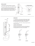
advertisement