
advertisement

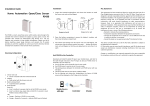
Mechanical Outline
2x Ø.125
1.50" 0.125" 2.50"
3.70"
3.75" 4.00"
4/30/98
4x Ø.125
0.25"
.875"
0.15"
3.00"
0.25"
User's Manual
3540 MO
Step Motor Driver
Copyright 1998
Applied Motion Products, Inc.
404 Westridge Drive • Watsonville, CA 95076
Tel (408) 761-6555 (800) 525-1609 Fax (408) 761-6544
motors • drives • controls
Technical Specifications
Amplifiers
Dual, bipolar MOSFET H-bridge, pulse width modulated three state switching at 20kHz. 12-42 VDC input. 0.4 - 3.5 amps/phase output current, switch selectable in 0.1 A increments. 122 watts maximum output power. Automatic idle current reduction (switch selectable), reduces current to 50% of setting after one second. Minimum motor inductance is 1 mH.
Inputs
Run/stop (cw limit), direction (ccw limit), hi/lo speed and enable inputs are optically isolated, 5-24V logic. 3 - 15 mA input current. 2200 ohms input impedance. Can be configured for sinking or sourcing signals.
Recommended external pot/joystick resistance: 1K - 5K .
Joystick dead zone: ± 80 mV.
Potentiometer/analog signal dead zone: 40 mV.
Recommended
Joystick
Maurey Instrument Corp., Chicago, IL (773)581-4555
JS31462S5T3 (2 axis) or SAJ2515-F-502 (1 axis)
Speed Ranges
LO speed range: 0 - 5 rev/sec
HI speed range: 0 - 25 rev/sec
Accel/decel range: 1 to 250 rev/sec/sec
Tach Output
Physical
Phototransistor, open collector, open emmiter.
24 volts max, 20 mA max
100 pulses per motor revolution, 50% duty cycle (square wave).
Mounted on 1/4 inch thick black anodized aluminum heat transfer chassis. 1.5 x 3.0 x 4.0 inches overall. Power on red
LED. See drawing on page 19 for more information. Ambient temperature range: 0 - 70 C.
Connectors
European style screw terminal blocks.
Power Supply & Motor: 6 position. Wire size: AWG 12 - 28.
Signal Input: 10 position. Wire size: AWG 16 - 28.
Microstepping
1/64 step (12,800 s/r) with 1.8 motor. Pure sine waveform.
-19-
Choosing a Power Supply
Voltage
Chopper drives work by switching the voltage to the motor terminals on and off while monitoring current to achieve a precise level of phase current. To do this efficiently and silently, you’ll want to have a power supply with a voltage rating at least five times that of the motor. Depending on how fast you want to run the motor, you may need even more voltage. More is better, the only upper limit being the maximum voltage rating of the drive itself: 42 volts (including ripple).
If you choose an unregulated power supply, do not exceed 30 volts DC. This is because unregulated supplies are rated at full load current. At lesser loads, like when the motor is not moving, the actual voltage can be up to 1.4 times the voltage listed on the power supply label.
Current
The maximum supply current you will need is the sum of the two phase currents.
However, you will generally need a lot less than that, depending on the motor type, voltage, speed and load conditions. That's because the 3540 MO uses switching amplifiers, converting a high voltage and low current into lower voltage and higher current. The more the power supply voltage exceeds the motor voltage, the less current you’ll need from the power supply.
We recommend the following selection procedure:
1. If you plan to use only a few drives, get a power supply with at least twice the rated phase current of the motor.
2. If you are designing for mass production and must minimize cost, get one power supply with more than twice the rated current of the motor. Install the motor in the application and monitor the current coming out of the power supply and into the drive at various motor loads. This will tell you how much current you really need so you can design in a lower cost power supply.
If you plan to use a regulated power supply you may encounter a problem with current foldback. When you first power up your drive, the full current of both motor phases will be drawn for a few milliseconds while the stator field is being established. After that the amplifiers start chopping and much less current is drawn from the power supply. If your power supply thinks this initial surge is a short circuit it may “foldback” to a lower voltage. With many foldback schemes the voltage returns to normal only after the first motor step and is fine thereafter. In that sense, unregulated power supplies are better. They are also less expensive.
The PS430 from Applied Motion Products is a good supply to use with the 3540 MO.
-18-
Table Of Contents
Introduction
Features
Block Diagram
Getting Started
Modes of Operation
Joystick Mode
Oscillator Mode
Speed Control from a 0 to 5 Volt Analog Signal
Tach Output
Connecting Digital Inputs and Limit Switches
Connecting the Motor
Microstepping
Setting Phase Current
Current Setting Table
Idle Current Reduction
Connecting the Power Supply
Mounting the Drive
Recommended Motors
Choosing a Power Supply
Technical Specifications
Mechanical Outline
-3-
17
17
18
19 back cover
11
11,12
12,13
14
14
15
16
16
6
6,7
8,9,10
9,10
4
5
4
4
Introduction
Thank you for selecting an Applied Motion Products motor control. We hope our dedication to performance, quality and economy will make your motion control project successful.
If there's anything we can do to improve our products or help you use them better, please call or fax. We'd like to hear from you. Our phone number is (800) 525-
1609 or you can reach us by fax at (408) 761–6544.
Features
• Digital oscillator provides smooth accel/decel ramps and precise speed control.
• Powerful microstepping amplifier provides high torque and smooth, quiet motion.
• Accepts a wide range of motors: NEMA sizes 14 - 34, 0.4 to 3.5 amps/phase.
• Accepts a wide range of DC power supply voltages: 12 - 42 volts DC.
• Easy to configure with on-board switches and potentiometers for all settings.
• Automatic idle current reduction reduces motor and drive heating, saves power.
• Screw terminal connectors make wiring easy.
• Can operate from internal pots, external pots, 0 - 5 V analog signal, or analog joystick.
• Two speed ranges, can be selected "on the fly" by a digital signal with automatic ramping between speeds.
• Also accepts simple, analog joystick.
• Compact size: 1.5 x 3 x 4 inches.
• Digital inputs are optically isolated, 5 - 24 volts, sourcing or sinking.
• Tach Out signal allows easy measurement of speed, optically isolated, 5 - 24 volts.
• Enable input allows motor current to be shut off on command.
Block Diagram
12-42 VDC
HI speed ext speed input
LO speed accel
50% idle current
0.4 to 3.5
A/phase
Digital Oscillator
&
Joystick Interface
Microstep
Sequencer
MOSFET
Amplifier
A+
A–
B+
B– to motor common run hi/lo speed direction enable tach out+ tach out-
Optical
Isolation
joystick ext speed
-4-
Mounting the Drive
You can mount your drive on the wide or the narrow side of the chassis. If you mount the drive on the wide side, use #4 screws through the four corner holes. For narrow side mounting applications, you can use #4 screws in the two side holes.
smooth flat surface
#4 screws
wide side mount narrow side mount
The amplifiers in the drive generate heat. Unless you are running at 1 amp or below, you may need a heat sink. To operate the drive continuously at maximum power you must properly mount it on a heat sinking surface with a thermal constant of no more than 4˚C/watt. Applied Motion Products can provide a compatible heat sink. Often, the metal enclosure of your system will make an effective heat sink.
Never use your drive where there is no air flow or where other devices cause the surrounding air to be more than 70˚C. Don't put the drive where it can get wet or where metal particles can get on it.
Recommended Motors
Motor
Number
Size inches
5014-842 1.38 x 1.38 x 1.57
HT17-068 1.65 x 1.65 x 1.30
HT17-071 1.65 x 1.65 x 1.54
HT17-075 1.65 x 1.65 x 1.85
5023-122 2.22 x 2.22 x 2.0
5023-123 2.22 x 2.22 x 3.0
5023-124 2.22 x 2.22 x 4.0
HT23-394 2.22 x 2.22 x 1.54
HT23-397 2.22 x 2.22 x 2.13
HT23-400 2.22 x 2.22 x 2.99
5034-348 3.38 x 3.38 x 2.50
Winding Max Torque Current
Connection oz-in Amps
4 lead parallel
19
23
1.0
1.0
parallel parallel parallel parallel
30
40
60
100
1.25
1.7
2.0
2.5
parallel parallel parallel parallel parallel
-17-
150
60
140
180
130
3.5
2.8
2.8
2.0
3.5
Idle Current Reduction
Your drive is equipped with a feature that automatically reduces the motor current by 50% anytime the motor is not moving. This reduces drive heating by about 50% and lowers motor heating by 75%. This feature can be disabled if desired so that full current is maintained at all times. This is useful when a high holding torque is required. To minimize motor and drive heating we highly recommend that you enable the idle current reduction feature unless your application strictly forbids it.
Idle current reduction is enabled by sliding switch #3 toward the
50% IDLE label,as shown in the sketch below. Sliding the switch away from the
50% IDLE label disables the reduction feature.
50% IDLE 50% IDLE
Idle Current Reduction Selected
No Current Reduction
Connecting the Power Supply
If you need information about choosing a power supply, please read Choosing a
Power Supply located on page 18 of this manual. The PS430 from Applied Motion
Products is a good supply for this drive.
If your power supply does not have a fuse on the output or some kind of short circuit current limiting feature you need to put a 4 amp fast acting fuse between the drive and power supply. Install the fuse on the + power supply lead.
Connect the motor power supply as shown below. Use no smaller than 20 gauge wire. Be careful not to reverse the wires. Reverse connection will destroy your driver, void your warranty and generally wreck your day.
4A fuse
DC Power
Supply
12-42 volts
+
–
Getting Started
To use your Applied Motion Products motor control, you will need the following:
• a 12-42 volt DC power supply for the motor. Please read the section entitled
Choosing a Power Supply for help in choosing the right power supply.
• a compatible step motor
• a small flat blade screwdriver for tightening the connectors
• For Joystick mode, you'll need an 3 terminal analog joystick with 1K - 5K impedance. If you want to use limit switches, you'll need normally open switches and a 5 - 24 volt power supply.
• For Oscillator mode, you'll need run/stop and direction signals (or switches).
Because the input circuits are optically isolated, you may also need a 5 - 24 volt
DC power supply. (See pages 8-10 for details.) If you want to control the motor speed externally, you need a 1K - 5K pot or a 0 - 5 volt analog signal.
The sketch below shows where to find the important connection and adjustment points. Please examine it now.
power connector
• DC power supply
• motor
mounting hole (1 of 6) trim pots
• accel/decel rate
• low speed
• high speed
-16-
DIP switches
• motor current
• idle current reduction
• joystick mode
• ext speed mode
Always use the blue & white Applied
Motion screwdriver with this connector. Larger screwdrivers may remove the plastic dimples that prevent the screws from falling out.
input connector
• run/stop (cw limit)
• dir (ccw limit)
• high/low speed select
• amp enable
• ext speed pot/joystick
• tach out
-5-
Modes of Operation
Note: We refer to an input as being ON when current is flowing through the input. A signal is OFF when no current is flowing. An input is OFF when COM and the input terminal are at the same voltage, or when the input is left unconnected (open).
The 3540 MO features two modes of operation.
• Joystick mode - speed and direction are determined by an external analog voltage. RUN and DIR inputs can be used for limit switches. SPD (speed) input selects speed range. LO SPEED and HI SPEED pots adjust the 2 speed ranges.
• Oscillator mode - speed can be controlled by on-board potentiometers and/or by an external analog voltage. RUN input starts and stops the motor. DIR input controls direction of rotation. SPD input selects the speed range.
Joystick Mode
In this mode, speed and direction are determined by the voltage applied to the WPR
(wiper) terminal. 2.5 volts is "stopped" (no speed). Increasing the WPR voltage toward 5 volts results in forward motion: speed increases with voltage. Decreasing the WPR voltage from 2.5 toward 0 results in reverse motion, with speed increasing as voltage decreases.
The maximum speed is determined by two things: the state of the SPD input and the HI SPEED and LO SPEED trimpots. When the SPD input is ON, the speed range of the joystick can be adjusted with the LO SPEED pot, up to 5 rev/sec (300 rpm)
When the SPD input is OFF (or open), the joystick speed range is adjusted with the
HI SPEED pot, up to 25 rev/sec (1500 rpm). Turning the pots clockwise increases the speed.
In joystick mode, limit switches can be connected to the 3540 MO to prevent motion outside of defined limits. The forward limit should be connected to the RUN input and the reverse limit should be connected to the DIR input. When the forward limit is ON, the motor will not move forward (that is, when the joystick voltage is between
2.5 and 5 volts.) When the reverse limit is ON, the motor will not move when the joystick is in the 0 to 2.5 volt range. If you don't need limits, you can leave the RUN and DIR inputs unconnected.
Joystick mode is set by moving switch #1 toward the word "Joystick". Switch #2
(EXT SPEED) has no effect in Joystick mode.
-6-
Current Setting Table
0.8
AMPS/
PHASE
0.1
0.2
0.4
0.8
1.6
0.9
AMPS/
PHASE
0.1
0.2
0.4
0.8
1.6
1.0
AMPS/
PHASE
0.1
0.2
0.4
0.8
1.6
1.1
AMPS/
PHASE
0.1
0.2
0.4
0.8
1.6
0.4
AMPS/
PHASE
0.1
0.2
0.4
0.8
1.6
0.5
AMPS/
PHASE
0.1
0.2
0.4
0.8
1.6
0.6
AMPS/
PHASE
0.1
0.2
0.4
0.8
1.6
0.7
AMPS/
PHASE
0.1
0.2
0.4
0.8
1.6
1.6
AMPS/
PHASE
0.1
0.2
0.4
0.8
1.6
1.7
AMPS/
PHASE
0.1
0.2
0.4
0.8
1.6
1.8
AMPS/
PHASE
0.1
0.2
0.4
0.8
1.6
1.9
AMPS/
PHASE
0.1
0.2
0.4
0.8
1.6
1.2
AMPS/
PHASE
0.1
0.2
0.4
0.8
1.6
1.3
AMPS/
PHASE
0.1
0.2
0.4
0.8
1.6
1.4
AMPS/
PHASE
0.1
0.2
0.4
0.8
1.6
1.5
AMPS/
PHASE
0.1
0.2
0.4
0.8
1.6
2.4
AMPS/
PHASE
0.1
0.2
0.4
0.8
1.6
2.5
AMPS/
PHASE
0.1
0.2
0.4
0.8
1.6
2.6
AMPS/
PHASE
0.1
0.2
0.4
0.8
1.6
2.7
AMPS/
PHASE
0.1
0.2
0.4
0.8
1.6
2.0
AMPS/
PHASE
0.1
0.2
0.4
0.8
1.6
2.1
AMPS/
PHASE
0.1
0.2
0.4
0.8
1.6
2.2
AMPS/
PHASE
0.1
0.2
0.4
0.8
1.6
2.3
AMPS/
PHASE
0.1
0.2
0.4
0.8
1.6
-15-
3.2
AMPS/
PHASE
0.1
0.2
0.4
0.8
1.6
3.3
AMPS/
PHASE
0.1
0.2
0.4
0.8
1.6
3.4
AMPS/
PHASE
0.1
0.2
0.4
0.8
1.6
3.5
AMPS/
PHASE
0.1
0.2
0.4
0.8
1.6
2.8
AMPS/
PHASE
0.1
0.2
0.4
0.8
1.6
2.9
AMPS/
PHASE
0.1
0.2
0.4
0.8
1.6
3.0
AMPS/
PHASE
0.1
0.2
0.4
0.8
1.6
3.1
AMPS/
PHASE
0.1
0.2
0.4
0.8
1.6
Microstepping
Most step motor drives offer a choice between full step and half step resolutions. In most full step drives, both motor phases are used all the time. Half stepping divides each step into two smaller steps by alternating between both phases on and one phase on. Microstepping drives like the 3540 MO precisely control the amount of current in each phase at each step position as a means of electronically subdividing the steps even further.
The 3540 MO divides each full step into 64 microsteps, providing 12,800 steps per revolution for precise positioning and smooth motion.
Setting Phase Current
Before you turn on the power supply the first time, you need to set the driver for the proper motor phase current. The rated current is usually printed on the motor label.
The 3540 MO drive current is easy to set. If you wish, you can learn a simple formula for setting current and never need the manual again. Or you can skip to the table on the next page, find the current setting you want, and set the DIP switches according to the picture.
Current Setting Formula
Locate the bank of tiny switches near the motor connector. Four of the switches have a value of current printed next to them, such as 0.4 and 0.8. Each switch controls the amount of current, in amperes (A), that its label indicates. There is always a base of current of 0.4 A. To add to that, slide the appropriate switches toward their labels on the PC board. You may need your small screwdriver for this.
Example
Suppose you want to set the driver for 2.2 amps per phase. You need the 0.4 A base current plus another 1.6 and 0.2 A.
2.2 = 0.4 + 1.6 + 0.2
Slide the 1.6 and 0.2 A switches toward the labels as shown in the figure.
0.1
0.2
0.4
0.8
1.6
-14-
25
20
15
10
5
0
-5
-10
-15
-20
-25
0
volts
COM
+
5-24
VDC
SUPPLY
-
fwd limit switch
RUN (FWD LIMIT)
DIR (REV LIMIT)
rev limit switch
SPD
joystick "fire" button
CW
fwd
5k
Ω joystick rev
WPR
CCW
Typical wiring for Joystick Mode
1 2 3
Speed vs Input Voltage
Joystick mode, SPD input off (or open)
HI SPEED pot at maximum
4
-7-
5
volts
Oscillator Mode
In oscillator mode, the 3540MO uses the direction set by the DIR input. Off, or open, gives clockwise motion, if the motor is wired according to pages 12 and 13.
Motor speed and the function of the RUN input can be determined from the following table.
SPD input switch
#2 speed set when RUN by goes ON when RUN goes OFF
ON joystick ext speed accel to speed instant stop
LO SPEED
ON joystick ext speed accel to speed instant stop
LO SPEED
OFF/open joystick ext speed accel to speed decel to stop
HI SPEED
WPR input
trimmed by
OFF/open joystick ext speed accel to speed decel to stop
HI SPEED
Oscillator mode is selected by moving switch #1 away from the word Joystick.
There are two speed ranges in oscillator mode. One is the low speed range, which is activated when the SPD input is on. The low speed can be set from 0 to 5 rev/sec
(0 - 300 rpm) by adjusting the LO SPEED pot. Turning the pot clockwise increases the speed.
The high speed setting is used when the SPD input is off, or open. If switch #2 is toward the words EXT SPEED, then the high speed is proportional to the voltage applied to the WPR terminal, and is trimmed by the HI SPEED pot. You can connect an external 1K - 5K pot to the WPR, CW and CCW terminals, or you can apply a 0 to
5 volt analog signal to the WPR terminal (ground your analog signal to the CCW pin.) The high speed range is 0 - 25 rev/sec (0 - 1500 rpm.) You can reduce the range by turning down the HI SPEED pot. For example, if you want the motor to go
750 rpm when the external pot is on maximum, turn the HI SPEED pot down about half way.
When switch #2 is away from the EXT SPEED label, the high speed is set by the HI
SPEED pot and the WPR input does nothing.
Never apply more than 5 volts DC or less than 0 volts to the WPR pin.
-8-
Four lead motors can only be connected one way. Please follow the sketch at the right.
A+
Red
4 lead motor
Six lead motors can be connected in series or center tap. In series mode, motors
A-
Blue
produce more torque at low speeds, but cannot run as fast as in the center tap
Yellow
White
configuration. In series operation, the motor
B+ Bshould be operated at 30% less than rated
4 Leads
current to prevent overheating. Wiring diagrams for both connection methods are shown below. NC means not connected to anything.
A-
Grn/Wht
NC
White
A+
Green
6 lead motor
Red/
Wht
A-
Grn/Wht
A+
White
6 lead motor
NC
Green
Red
B-
Black
B+
Red/
Wht
NC
Red
B-
Black
NC B+
6 Leads Series Connected 6 Leads Center Tap Connected
Eight lead motors can also be connected in two ways: series or parallel. As with six lead motors, series operation gives you more torque at low speeds and less torque at high speeds. In series operation, the motor should be operated at 30% less than the rated current to prevent over heating. The wiring diagrams for eight lead motors are shown below.
A+
Orange
A+
Orange
Blk/Wht
Org/Wht
Blk/Wht
A-
8 lead motor
Org/
Wht
A-
8 lead motor
Black
Black
Red
Yel low
Red
Red/
Wht
B+
Yel/
Wht
B-
Yellow
B+
Yel/
Wht
Red/Wht
B-
8 Leads Series Connected 8 Leads Parallel Connected
-13-
open collector TTL devices are directly compatible with this drive, as are typical
PLC and proximity sensor outputs.
Sinking Circuits (NPN)
If your output devices prefer to sink current, then connect the COM terminal to your positive power supply. If you are using a TTL circuit to drive the 3540 MO, connect the COM terminal to your 5 volt bus. No ground connection is needed. If you are using a PLC or proximity sensor, you'll need a power supply.
Sourcing circuits (PNP)
If your output devices can only source current (some PLC outputs are this way), connect the COM terminal to the ground of the DC power supply that powers your output circuits.
Note: We refer to an input as being ON when current is flowing through the input. A signal is OFF when no current is flowing. An input is OFF when COM and the input terminal are at the same voltage, or when the input is left unconnected (open).
The ENABLE input allows the user to turn off the current to the motor by setting this signal on. The logic circuitry continues to operate, so the drive "remembers" the step position even when the amplifiers are disabled. However, the motor may move slightly when the current is removed depending on the exact motor and load characteristics. If you have no need to disable the amplifiers, you don't
need to connect anything to the
ENABLE input.
Connecting the Motor
Warning: When connecting the motor to the driver, be sure that the motor power supply is off. Secure any unused motor leads so that they can't short out to anything. Never disconnect the motor while the drive is powered up. Never connect motor leads to ground or to a power supply!
You must now decide how to connect your motor to the drive. Page 13 shows several ways to connect your motor to the 3540 MO.
-12-
In both operating modes, the accel/decel rate is set by the ACCEL pot. The range is 1 to 250 rev/sec/sec. Turning the pot clockwise makes the motor start and stop faster, but if you set it too high the motor may run out of torque and stall.
In nearly all cases, the accel/decel rate you set is respected by the 3540 MO. For example, if you switch the SPD input while the motor is moving, the drive will change speeds smoothly. If you are operating in EXT SPEED mode and make a sudden change in the voltage to the WPR terminal, the drive accelerates (or decelerates) to the new speed smoothly, according to the accel pot setting.
The only time the drive makes an instant change is when the SPD input is on and the RUN input goes off. That is done so that you can stop instantly (and exactly) from a low speed.
+
5-24
VDC
SUPPLY
-
run/stop switch
(closed=run) direction switch
COM
RUN
DIR
speed switch (closed=lo speed) cw
5k
Ω pot ccw
SPD
CW
WPR
CCW
Typical wiring for Oscillator Mode using external speed control pot
Speed Control from a 0 to 5 Volt Analog Signal
In oscillator mode, the 3540MO can rotate the motor a speed proportional to an analog voltage. The voltage must be applied to the WPR terminal. The direction of rotation will be controlled by the digital DIR input and the motor can be stopped either by setting the analog input voltage to 0 or by turning the digital RUN signal off.
To use the 3540 MO in this mode, set switch #1 away from the
JOYSTICK label, and set switch #2 toward the EXT SPEED label.
joystick ext speed
-9-
The HI SPEED pot sets the maximum speed (the motor speed when the analog siognal is at 5 volt DC). The range is 0 - 25 rev/sec.
Wiring diagrams and a plot of speed vs voltage are shown below.
+
5-24
VDC
SUPPLY
-
run/stop switch
(closed=run)
0 - 5V speed signal direction switch signal return
COM
RUN
DIR
WPR
CCW
Wiring for Speed Control by 0 - 5 Volt Analog Signal
(Direction Control by Digital Signal or Switch)
0 - 5V speed signal signal return
Wiring for Speed Control by 0 - 5 Volt Analog Signal
(Unidirectional Rotation)
25
20
COM
RUN
CW
WPR
CCW
15
10
5
0
0 1 2 3 4
Speed vs Input Voltage
EXT SPEED mode, HI SPEED pot at maximum
5
-10-
Tach Output
The Tach Out signal is provided for measuring the motor speed. It generates 100 pulses per revolution, so if you connect a frequency counter, the speed reads out in revs/second with two decimal places. The schematic diagram of the Tach Out optoisolation circuit is shown below.
Do not connect the Tach output to more than 24VDC.
The current into the Tach+ terminal must not exceed 20 mA.
4700
Ω
+
–
5 - 24V
DC
Power
Supply
+5V
330
Ω internal tach signal
inside 3540 MO
Optoisolator
NEC PS2501 or equiv.
Internal Tach Circuit
TACH+
TACH–
TACH+
TACH–
IN
GND
Freq
Counter
Connecting Tach Output to a Frequency Counter
Connecting Digital Inputs and Limit Switches
The 3540 MO contains optical isolation circuitry to prevent the electrical noise inherent in switching amplifiers from interfering with your circuits. This arrangement also allows a wide range of input voltages to be used and gives you the option of using sinking or
COM sourcing inputs.
A schematic diagram of the input circuit is shown on the right.
RUN
DIR
You must supply 5-24 volts DC to supply current to the LEDs on the input side of the optoisolators.Your controlling
EN
SPD logic must be capable of sinking or sourcing at least 3
Input Optoisolation Circuit
mA at 5 volts and 10 mA at 24 volts to control each drive input. Most CMOS and
-11-
advertisement
* Your assessment is very important for improving the workof artificial intelligence, which forms the content of this project
Related manuals
advertisement