advertisement

POWER SUPPLIES SPS1000 SERIES
CIRCUIT DESCRIPTION AND OPERATING MANUAL
CIRCUIT DESCRIPTION
Power Supplies SPS 1000 series are based on the primary switched AC/DC converters topology.
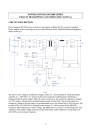
Power supplies of this technology have got a high efficiency factor. Simplified functional diagram is shown in the fig.1.
L U1
N N1
S W ITCH
F1
Input filter
P E t
NTC t
NTC
U
1
Input rect.
C f1 S
Inverter
P TC1
TR
U
2
Output rect.
P TC2
TL
C f2 F2
Output filter
+
U2
I2
-
Option
M
M
ROV
Fans speed control
RS 232
Už
I ž
RO
Control circuit
U ž I ž
I m
Um
I m
ZJ
Display unit
Um
"ON" "OFF"
"OFF"
+5V
"ON"
(Disable)
"OUTP UT"
S witch
+5V
Fig.1
The 230 AC line voltage is rectified by a bridge rectifier „U
1
“ and smoothed by a large electrolytic capacitor „C f1
“. RFI filters „F
1
“ protect the line and a load from a high frequency interference produced inside the power supply. When the unit is switched on, the electrolytic capacitor is charged via NTC resistors. Inrush current is limited approximately to 60A/10ms. This must be taken into account at a fusing of the line outlet. It is recommended to use 16A normal fuse or 10A slow one. The rectified 230V AC (300V DC) is chopped by the inverter „S“ which consists of four MOSFET transistors and transformed to a lower voltage. The 50kHz power converter is of full bridge type. The regulation of the output voltage (current) is achieved by pulse-width modulation varying duty cycle
(D=0 ÷ 80%) at the constant frequency.
1
The lower voltage is rectified by the output rectifier „U
2
“ and smoothed by a storage choke „TL“ and large electrolytic capacitor „C f2
“. An output filter „F2“ suppresses high frequency interference products.
Heart of the control circuits is a controller, which comprises PWM modulator, an error amplifier, and
5,1V reference, oscillator and totem pole output stage. Secondary side consists of the voltage and current regulators, 5V/0,5A reference for powering display unit and precise 5V/5mA reference for command signal setting. Current regulator output signal passes via an optocoupler to the error amplifier input.
The settings of output DC voltage and a current limitation can be reached trough the built-in potentiometers – ROUGHLY in the range 0 ÷ 95% of U max
(I max
).
(I max
) and FINE in the range 0 ÷ 5% of U max
The built-in insulated interface RS 232 and the external analogue one are optionally available to set the output voltage and current. The external analogue interface should be equipped by two external
DC/DC (5V/5V) insulated converters. One for voltage setting and the second one for current. Under remote control condition the REMOTE switch must be switched on and the FINE potentiometers must be turned to the left zero position.
Output voltage and current are picked-up and come both to the control circuit and display unit.
Voltage is indicated on the 3-digit display and the current at the same time on the 3-½-digit display.
Power supply output may be turned on or off by the Disable OUTPUT switch at any time independently on the load. Turning unit on or off by a mains switch may be also done at any position of this switch. It is recommended to use Disable OUTPUT switch prior to the mains switch to disconnect a load. Input circuit devices (NTC, diodes, capacitors) stress will be decreased. Mains current will be less than 0,1 Amps during STAND-BY state. This makes it possible to leave the input power on and use disable OUTPUT switch for turning on and off. Turning output off takes app. 0,1s and turning on of soft start process takes app. 2s until a duty cycle doesn’t reach max. value. Real output voltage falls to zero depending on the load. There is no output current sink capability. Bleed resistor connected across a filter circuit discharges capacitors when the unit is turned off. Only a few mAmps discharge current source improves this feature.
From an auxiliary mains transformer are powered both the primary side control circuits (30V AC) and secondary one (12V AC) which involves also display unit circuits and fans speed control circuits.
PTC thermistors pick-up a temperature of the both heat sinks.
CONSTRUCTION DESCRIPTION AND COOLING
Power circuits are placed on the main mother PCB. Display unit is soldered to it and control unit is connected via a connector. Further elements lay-out and cooling system shows following fig.2.
2
Optionally, instead of RS 232 interface, a connector may be fitted on the rear panel to connect an analogue interface. In the bottom and top cover of the steel case are created slots for an air intake.
This slots are covered by a fine net. Cooling air passes along heat sinks and goes out through a rear panel. Efficient cooling needs following an unobstructed area between:
- a table and bottom cover - min. 15 mm
- stacking of two units - min. 20 mm
- a rear panel of the unit and a wall - min. 100 mm
OPERATING INSTRUCTIONS
Power Supplies SPS 1000 series of class I equipment should normally be connected via a 3 line cable to mains PH+N+PE 50Hz, 230V ± 10%/TN-S. Protection achieved by basic insulation and connection to earth for all conductive parts that are capable of assuming hazardous voltage if the basic isolation fails. An output secondary circuit with voltages between conductors and between any conductor and earth, not exceeding 100V DC (basic enviroment), under normal operating conditions, which is separated from hazardous voltage by at least basic insulation, and which meets neither the requirements for an SELV circuit nor the requirements for a limited current circuit.
Between output and input circuit (main and auxiliary transformers) is used reinforced insulation and creepage and clearance distance is 8mm. Based on above mentioned Power Supplies SPS 1000 series appear to be a safety equipment.
Handling and operation of the SPS 1000 is very simple.
3
TURNING ON
* REMOTE switch turns to „OFF“ position
* All potentiometers move to the left zero position demand
* Disable OUTPUT switch move to „ON“ position
* Connect a load
* Cable plug insert to a socket
- local control mode
- only advice, it’s not strong
- its not strong demand
- it’s not necessary
* Switch on the mains switch – position „ON“
(mains switch indicator and both LED displays light on)
* Set assumed current limitation by potentiometers
(ROUGHLY or FINE)
* Set desirable output voltage on the both displays
may be observed real date of the voltage or current
* Set assumed max. voltage depending on the max.
load resistance and max. constant current
- in CV mode
- in CC mode
* Set desirable constant current within constant
current range
During operation in CV or CC mode an output power supply may be interrupted and restarted again by the disable OUTPUT switch.
TURNING OFF
It’s recommended to turn the load off, first by the disable OUTPUT switch and to remove wires from the output terminals. Than the mains switch may be turned off. Unit may be switched off directly by the mains switch at any operating condition.
MAINTENANCE
Power Supply SPS 1000 normally needs no maintenance or calibration. Only care must be taken not to obstruct cooling of the unit. When a unit is equipped by a dust filter, which must be cleaned or changed for a new one at the least once per year. The built-up of dust on the impellers of the fans and the heat sinks fins depends on the environment. Since the fans have over-capacity dust will not present a problem very quickly. The internal construction of the power supply is such that no dust wouldn’t reach the sensitive control circuit. There may occur a dust between the heat sink fins. It is advisable to inspect the fans, heat sinks as well as all units regularly.
IMPORTANT ADVICE AND CAUTION
- Electric strength (EDV) tests should not be repeated in the field. Improper test methods can cause severe damage to the power supply. Electric strength and earth continuity tests have been performed in the factory on each unit. The 4000V rms
cannot be tested afterwards on the assembled unit because the insulation between the components on the input side to the case is specified at 2000V rms
. Since
the insulation output-case is low (only 500V DC due to fans) the insulation of the primary
components to case will break down when 4000V rms
is applied between input and output
4
(2000V rms
+ 500V DC < 4000 V rms
).
- High energy may be stored in the output capacitors. Don’t cause a short circuit across the output.
- Don’t remove wires from the output terminals under load condition, especially at the higher voltage.
There probably will occur an arc, which may damage the unit. First turn off a load by disable
OUTPUT switch.
- The time between turning mains switch off and on must be min. 60s.
- The same type should replace fuses.
- Output voltage indicated on the display after turning disable OUTPUT switch off is present until output capacitors discharge (depends on the load).
- To avoid overheating the output capacitors by a pulsating load, the AC component of the load current should be limited. One method of decreasing the AC current on the output capacitor is by using a large external electrolytic capacitor in parallel with load. This also reduces problems of the inductance in a long lead. Care must be taken so that the capacitor in combination with the load inductance will not form a serial resonant circuit.
- The output voltage is available 2s after mains switch on. This feature may be improved according to customer requirements.
- Serial operation is allowed up to 300V total voltage. The power supplies can be connected in series without special precautions.
- Parallel operation of the two units without active current sharing is allowed. It is recommended to connect a diode per each unit – anode to plus terminal, cathode to common load and to set the same voltage on both units at the turning disable OUTPUT switch off. When the both output voltages are not the same nothing terrible happen because each unit has a current limitation. In parallel operation may occur a higher ripple voltage which my be up to 2 times of the normal ripple voltage value. In case of short circuit at any of the outputs of paralleling units, both units result short – circuited.
- Reverse polarity protection can be achieved with an external fuse combined with a rapid diode as in following figure 3:
SPS1000
incorrect polarity of the battery
Fig.3
This case may occur especially in the battery charger application. After applying reverse polarity
5
without protection elements the unit has to be sent to the producer for repair.
- Overvoltage at the output may damage the power supply. Coming from reliable operation of the units have been already made, those are not equipped with any OVP circuit. The OVP protection in the case of an active load (DC motor) may be done by two external rapid diodes connected according to following figure 4:
D2
SPS1000 D1
Fig.4
In the event of passive inductive resistor load (solenoid), there must be used a rapid diode D1 at least. The adjustable thyristor crowbar protection against internally as well as externally caused overvoltages may be delivered as an option or may be made by a customer qualified person. In generally, it’s difficult to predict max. allowed overvoltage in the case of the continuously controlled output voltage power supply. The 3V margin would be dangerous at 5V output for powering a TTL logic and lower one could be able to trigger the thyristor crowbar under normal operating condition due to a disturb noise.
- Avoid condensation inside the power supply, break-down could be the result. Condensation may occur during a period when the power supply is switched off and the ambient temperature is low.
Always allow the power supply to dry before switching it on again.
- An aggressive enviroment with acid, salt, etc. can harm the electronic components, afterwards pcboards may be dissolved.
- Don’t remove top or bottom cover of the case under operating conditions. Dangerous voltage may cause a serious injury.
CALIBRATION
When there is a suspicion of incorrect display reading value of current or voltage, only qualified person may do a calibration.
First needs to be adjusted reference voltage 5V source by trimer R241 on the control unit. Then may be adjusted correct voltage by trimer R301 and current by trimer R401. Both are placed on the display unit.
Enclosure: Interface RS 232 instruction manual or Analogue interface instruction manual.
6
RS 232 INTERFACE INSTRUCTION MANUAL
Power Supply SPS 1000 can be also remotely controlled by the RS 232 C serial interface from a personnel computer or by another device comprising this serial interface.
Connection procedure:
1. Connect CANON9 connector on the rear side of the power supply and computer serial port with a serial cable.
2. Set-up serial port: 1200 baud, 8 bits, no parity, 1 stop bit.
Example: MODE COM1: 1200,N,8,1
3. Set remote control switch to position REMOTE.
4. Move disable OUTPUT switch to position ON.
5. Fully turn to the left both fine potentiometers for current and voltage.
6. Switch on power supply and send following ASCII string through serial port: "SZU90,0I11,00E" , after this string send character 0x0D (ENTER)
Meaning of each symbol:
S …beginning of message
Z…power supply switched ON (V…power supply switched OFF). Tu switch OFF power supply, resp. his output, zero voltage and current shall be set.
U90,0 means setting voltage 90,0V (max. 99,9V)
I05,00 means setting current limit to 5,00 A (max. current range is up to approx. 12,5 A)
E…end of message
It is necessary to keep always the same string length. It means that needed voltage 5 V is entered as U05,0 and current 0,5 A as I00,50.
After sending correct string is the requested voltage and current limit set on the power supply.
Power supply does not confirm message reception.
Wire connection of communication cable to connect to IBM PC compatible computer:
POWER SUPPLY COMPUTER (CANON 9-pin)
XS1:2 XS2:3
XS1:5 XS2:5
XS2:4-----XS2:6
XS2:7-----XS2:8
Maximal distance between power supply and computer is 10m. (RS232 C)
7
advertisement
* Your assessment is very important for improving the workof artificial intelligence, which forms the content of this project
Related manuals
advertisement