advertisement
▼
Scroll to page 2

PRODUCT DATA
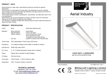
Aerial Industry is a high output, high efficiency high bay luminaire for general
applications.
The luminaire is constructed from sheet steel, polycarbonate and acrylic materials.
Aerial Industry incorporates the latest high efficiency LED light engines and drivers for
optimum efficiency and luminaire life.
The luminaire range includes a Quadraprism, Opal diffuser, and High Rack optic to suit
most applications.
Aerial Industry can be wire suspended or surface / trunking / drop rod mounted by
utilizing one of the optional suspension kits available.
The luminaire is supplied complete with external plug and socket cable terminations for
speed and ease of wiring.
Aerial Industry
PRODUCT SPECIFICATION
Finish:
Body
- White high reflective paint
Materials:
Body Assembly
Rear Backplate
Diffuser Options
- Sheet Metal
- 0.9mm mild steel
- 2.5mm Quad Prism Acrylic
- 2mm Opal Satine Acrylic
- 15 degree lens with clear diffuser.
- Injection moulded white Polycarbonate.
End cap
Control Gear:
DALI addressable or Fixed output LED Drivers.
Emergency:
3 hr integral emergency pack (Refer to website for options)
Light Source:
4000k high output LED’s
Op. Temp:
0 - 35 °C (Model dependant, please refer to website)
Power:
Please refer to website for latest Wattage
IP Rating:
IP40 front & rear
Connection:
Plug & Socket - 2.5mm2 maximum cable
Suspension:
Wire / Trunking / Surface / Drop Rod
HIGH BAY LUMINAIRE
INSTALLATION INSTRUCTIONS
PK/LEAFAERIND
Supply:
Connection:
TECHNICAL SUPPORT
Telephone: 0161 331 5700
240V [email protected]
AC, 50Hz
E-mail:
http://www.whitecroftlighting.com
1.5mm SQ Panel mount plug & sockets on rear face
OCTOBER 2018 - Rev C
Whitecroft Lighting Limited
Burlington Street, Ashton-under-Lyne, Lancashire OL7 0AX
Telephone +44 (0)161 330 6811 Facsimile: +44 (0)161 331 5855
Registered No. 3848973 England
Registered Office: As above
GENERAL INFORMATION
INSTALLATION INSTRUCTIONS
1.
PRE INSTALLATION
1. Remove the luminaire from packaging and inspect the contents for damage.
2. Ensure that the supporting ceiling structure is of adequate strength to support
the weight of the luminaire. (see table for weights)
2.
3.
4.
5.
A qualified electrician, in accordance with IEE wiring regulations, should carry out connection
to mains wiring.
This luminaire must be EARTHED.
Ensure that the rated luminaire voltage and frequency requirements are compatible with the
available mains supply.
Cleaning of lenses should be carried out using a lint free cloth and anti-static cleaning fluid.
The luminaire body will become hot under normal operating conditions. Allow to cool before
undertaking any necessary maintenance work.
PRODUCT DIMENSIONS (All dimensions are in ‘mm’.)
1430
1410
110
190
1018
WIRE SUSPENSION KIT OPTION - 5m (supplied separate)
1. Loop the suspension cable around a suitable load bearing structure at the
approximate centres indicated. Fit the gripple clutch & suspension toggle
‘Y’splitter to the cable and adjust to the desired height making reference to
the separate suspension kit instructions.
2. Support the weight of the luminaire from below and then offer the ‘Y’ splitter
toggles through the slots indicated on the back of the luminaire at each end.
3. Check luminaire height and level if necessary via the adjustable clutch
mechanisms (Nb support the luminaire weight when adjusting). Trim off any
excess cable only when happy with the luminaire suspension height.
O 21
O8
310,5
86,75 47,6
OPTIONAL SURFACE MOUNT/TRUNKING/DROP ROD BRACKET.
1421
TRUNKING /SURFACE MOUNT KIT OPTION - (supplied separate)
1 Slide the support brackets into the four slots at each end of the luminaire and
secure in place via the two self tapping screws provided.
2 Fit the supplied tee piece plug adaptors to the sockets to enable side entry of
the connection plugs.
3 If suspending from trunking use a suitable 20mm adaptor (not supplied).
4 If suspending via drop rods, use 8mm rod at centres indicated.(not supplied)
5 If surface mounted use suitable fixings at centres indicated.(not supplied)
NB – If the luminaire is being suspended via customer preferred method, eg drop rods or
chains, then a surface mount kit must be utilized to facilitate fit. (ordered separate).
MAINS CONNECTION PLUG.
DALI CONNECTION PLUG.
COMEPS CONNECTION PLUG.
DROP ROD & SURFACE
SUSPENSION POINT.
TRUNKING SUSPENSION
POINT.
REMOVE REAR COVER TO ACCESS
BATTERY CONNECTIONS.
SURFACE MOUNT &
TRUNKING KIT OPTION.
ABTRU
PART REF: AETMTRU
GENERAL WIRING INFORMATION
1. Wire the plugs in accordance with the schematic detailed below noting location
of Dali and COMEPS sockets. Connect plugs into relevant sockets in the rear
of the luminaire and test for correct operation.
2. If the luminaire is an emergency variant, connect the battery leads and mark
the installation date. Access to batteries can be gained from the rear of the
luminaire by removing the gear cover (4 screws). NB Battery connection must
be undertaken before installation of luminaire if surface or trunking mounted.
3. If fixed output operation is required, installer must fit link cable within Dali plug
‘N’ & ‘L’ terminals as detailed below.(Nb Link not required for Dali operation)
Warning: The LEDs in this luminaire operate at HIGH VOLTAGE.
Ensure that the luminaire is isolated before opening.
advertisement
* Your assessment is very important for improving the workof artificial intelligence, which forms the content of this project
