advertisement

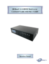
HDBaseT 4×4 HDMI Matrix over
CAT5e/6/7 Cable with PoE # 15281
Operation Manual
Introduction
Features
Applications
The HDBaseT™ 4 by 4 HDMI Matrix over CAT5e/6/7 supports the transmission of video (resolutions up to 1080p Full HD and
1920×1200@60Hz) and multi-channel digital audio from four high definition sources to four outputs over a single CAT5e/6/7 cable (up to 100m) for each output. It supports high resolution digital audio formats such as LPCM
7.1CH, Dolby TrueHD, Dolby Digital Plus and DTS-HD Master Audio as well as 3D content that can be displayed when connecting a 3DTV and 3D source. The matrix can be controlled via IR, RS-232, Telnet or Web GUI.
Power over Ethernet (PoE) support means that compatible receivers do not need their own seperate power supplies, allowing for greater flexibility in installations.
•
HDMI, HDCP1.1 and DVI compliant
• Supports HDMI 3D features
•
Supports resolutions VGA~WUXGA and 480i~1080p dependent upon the output display’s EDID settings
•
Supports 3D signal display dependent upon the output display EDID settings
•
Supports PoE (Power over Ethernet) on compatible receivers only
•
Supports HDMI input up to 15 meters at 8-bit resolution or 10 meters at 12-bit resolution
•
Supports bi-directional IR to and from input and output locations
•
Supports control via RS-232, IR remote, on-panel buttons and IP
(Telnet & Web GUI)
•
2U size design
• Supports external and internal EDID settings
•
Supports LPCM 7.1CH, Dolby TrueHD, Dolby Digital Plus and DTS-HD
Master Audio transmission
Note:
1. The PoE function is designed for powering compatible receiver units only—non-PoE receivers will need their own power supply.
Receivers of another brand may not be compatible.
2. Do not connect the LAN/CONTROL port to CAT outputs of this device
• HDMI Matrix System
• Video/TV wall display and control
•
Security surveillance and control
•
Commercial advertising, display and control
• University lecture hall, display and control
•
Retail sales and demonstration
System Requirements
•
HDMI equipped source devices, connect with HDMI cables or DVI
equipped source, connect with DVI to HDMI cables
•
HDMI equipped displays (TVs or monitors) or HDMI equipped AV
receivers, connected with HDMI cables
•
Industry standard CAT5e/6/7 cables
• HDBaseT™ Receivers
Operation Controls and Functions
Front Panel
1.
LCM:
Displays the setting information of each input and output setting.
2.
POWER:
Press this button to power the device on/off. The LED will illuminate green when the power is on, red when it is in 'Standby' mode.
3.
LOCK:
Press this button to lock all the buttons on the panel; press again to unlock.
The LED will illuminate green when locked.
4.
IR:
IR Receiver window (accepts the remote control signal of this device only) with IR frequency of 38kHz.
5.
MENU:
Press this button to access the LCM menu system, from here EDID settings can be managed and IP system settings are displayed.
6.
1~4/A~D and OUT/IN:
Press the OUT or IN button to select the output or input mode and then press the required number button to make the selection accordingly.
For example, if outputs A~B need to be set to input 1 and outputs C~D need to be set to input 2, then the following sequence of button presses need to be performed:
Press: OUT►A►B►IN►1►MENU, and then press:
OUT►C►D►IN►2►MENU.
Note: If the MENU button is not pressed the selection will not be changed.
Back Panel
1.
CONTROL:
This port is the link for Telnet or Web GUI controls, connect to an active
Ethernet link with an RJ45 terminated cable (for further details on IP control, please refer to sections on Web GUI and Telnet Control).
Warning: Please do not connect this port directly to the PC/Laptop as the
Telnet function will not work.
2.
RS-232:
Connect to a PC or control system with D-Sub 9-pin cable for control of the matrix via RS-232 commands (please refer to Section on Telnet and RS-
232 commands for a list of commands).
3.
ALL IR OUT:
Connect to the IR blaster for IR signal transmission to the source devices.
Place the IR blaster in direct line-of-sight of the equipment to be controlled.
All signals received from the display side will be relayed to the source devices.
4.
ALL IR IN:
Connect to the IR extender for IR signal reception. Ensure that the remote being used is within the direct line-of-sight of the IR extender. It will transmit all signals received through the IR ALL OUT.
5.
SERVICE:
Manufacturer use only.
6.
IR OUT A~D:
Connect to the IR blasters for IR signal transmission. Place the IR blaster in direct line-of-sight of the equipment to be controlled. It will transmit the IR signal received from the receiver side according to the selected input.
7.
IR IN 1~4:
Connect to the IR extenders for IR signal reception. Ensure that the remote being used is within the direct line-of-sight of the IR extender. It will send out the IR signal received to the selected IR OUT (A-D).
8.
CAT5e/6/7 OUT A~D:
Connect the CAT outputs to the CAT input port of the receiver units with a single CAT5e/6/7 cable for HDMI Audio/Video and IR control signal transmission.
Warning: Please do not connect the CAT5e/6/7 outputs to the receiver's LAN port.
9.
HDMI IN 1~4:
Connect to the HDMI source devices such as a DVD player or a Set-top
Box with HDMI cables or DVI to HDMI cables.
10.
DC 24V:
Connect the 24 V DC power supply to the unit and plug the adaptor into an
AC outlet.
11.
PoE 24V:
Connect the 24V PoE power supply into the unit and plug the adaptor into an AC outlet. This unit will mainly power PoE (Power over Ethernet) capable receiver units.
Side Panel
Remote Control
1.
Fan Ventilator:
These are air ventilation areas, DO NOT block these areas or cover it with any object. Please allow adequate space around the unit for air circulation
1.
POWER:
Press this button to switch the device 'ON' or set it to standby mode.
2.
IN:
Input selection 1~4.
3.
OUT:
Output selection A~D.
Note:
1. When the IR remote is used in the
Output Zone the user only needs to select the desired input (1~8)
2. 5~8 and E~H buttons are not functioning.
IR Cable Pin
Assignments
RS-232 Pin
Assignments
5
6
3
4
HDMI MATRIX
PIN ASSIGNMENT
1
2
N/C
Tx
Rx
N/C
GND
N/C
►
◄
7
8
N/C
N/C
7
8
9 N/C 9
Baud Rate: 19200 bps Parity: None
Data Bit: 8-bit
Flow Control: None
Stop Bit: 1-bit
5
6
3
4
REMOTE CONTROL
PIN ASSIGNMENT
1
2
N/C
Rx
Tx
N/C
GND
N/C
N/C
N/C
N/C
RS-232 and
Telnet Commands
A1~A4
B1~B4
C1~C4
D1~D4
COMMAND
ABCD...1~ABCD...4
DESCRIPTION
Switch Output A to 1~4
Switch Output B to 1~4
Switch Output C to 1~4
Switch Output D to 1~4
Switch Output ABCD... to 1~4 at the same time
Setting IP. SubNet. GateWay<Static IP>
SETIP <IP>
<SubNet><GW>
RSTIP
IPCONFIG
P0
P1
I1~I4
ST
RS
EM
?
QUIT
IP configuration was reset to factory defaults<DHCP>
Display the current IP config
Power Off
Power On
Switch all the output to 1~4
Display the current matrix state and firmware version
System Reset to D4
Setting EDID MODE. 1-STD 2-TV
Display all available commands
Exit (Telnet only)
Note:
1. Commands will not be executed unless followed by a carriage return. Commands are case-insensitive.
2. When the Telnet connection is idle for 10 minutes it will be automatically disconnected.
3. The TV EDID setting will always follow output port 1's EDID setting regardless of the output change.
4. EDID setting switching will execute immediately.
Telnet Control
Before attempting to use the Telnet control, please ensure that both the HDMI
Video Wall unit (via the ‘CONTROL’ port) and the PC/Laptop are connected to the active networks.
To access the Telnet control in Windows 7, click on the ‘Start’ menu and type
“cmd” in the Search field then press Enter. Under Windows XP go to the
‘Start’ menu and click on “Run”, type “cmd” with then press Enter.
Under Mac OS X, go to Go→Applications→Utilities→Terminal. See below for reference.
Once in the command line interface (CLI) type "telnet", then the IP address of the unit and "23", then hit enter.
Note: The IP address of the Matrix can be displayed on the device's
LCM monitor by pressing the Menu button twice.
This will bring us into the unit which we wish to control. Type 'HELP' to list the available commands.
Type “IPCONFIG” To show all IP configurations. To reset the IP, type
“RSTIP” and to use a set static IP, type ”SETIP” (For a full list of commands, see Section Telnet and RS-232 commands).
Note: Commands will not be executed unless followed by a carriage return. Commands are not case-sensitive. If the unit's IP is changed then the IP Address required for Telnet access will also change accordingly
CAT5e/6/7 Cable Specifications
CABLE
TYPE
RANG
E
CAT5e/6/7 100m
70m
PIXEL
CLOCK
RATE
VIDEO
DATA
RATE
≤225 MHz ≤ 5.3 Gbps
(HD Video)
>225 MHz
> 5.3 Gbps
(Ultra HD
Video)
SUPPORTED VIDEO
Up to 1080p, 60 Hz,
36 bits, 3D (data rates lower than 5.3
Gbps or below 225
MHz TMDS clock)
4K×2K, 30Hz video formats
Web GUI
Control
On a PC/Laptop that is connected to the same active network as the
Matrix, open a web browser and type the device's IP address on the web address entry bar. The browser will display the device's status, control and
User setting pages.
Click on the 'Control' tab to control power, input/output ports, EDID and reset mode
Clicking on the 'User Setting' tab allows you to reset the IP configuration.
The system will ask for a reboot of the device when any of the settings are changed. The IP address needed to access the Web GUI control will also need to be changed accordingly on the web address entry bar
Specifications
Video Bandwidth
Input Ports
Output Ports
IR Frequency
Supported Resolutions
225 MHz/6.75 Gbps
4×HDMI, 5×IR Extender, 1×RS-232, 1×RJ-
5 (Control), 1×Mini USB Type B (For firmware updated only)
4×CAT5e/6/7, 5×IR Blaster
30~50 kHz
HDTV: 480i~1080p50/60 & 1080p24
PC: VGA~WXGA
HDMI Input Cable Length
15m (1080p@8-bit)
10m (1080p@12-bit)
Audio Sampling Rate
ESD Protection
Up to 192 kHz
Human-body Model:
Power Supply
± 8kV (Air-gap discharge)
± 4kV (Contact discharge)
24V/6.25A DC (US/EU standards, CE/
FCC/UL certified)
Dimensions
Weight
Chassis Material
Color
Operating Temperature
Storage Temperature
Relative Humidity
Power Consumption
438mm (W)×255mm (D)×93mm (H)
4238 g
Metal
Black
0 ºC~40 ºC/32 ºF~104 ºF
−20 ºC~60 ºC/−4 ºF~140 ºF
20~90% RH (non-condensing)
42W/TX (Main), 27W/RX (PoE)
Connection Diagram
advertisement
* Your assessment is very important for improving the workof artificial intelligence, which forms the content of this project
Related manuals
advertisement