
advertisement

THERMOLEC
Installation instructions for
Plenum-mounted add-on electric heaters
MODEL TU
AUGUST 2004
VERSION 6
THERMOLEC PLENUM HEATER MODEL TU
BEFORE YOU START - GENERAL SAFETY AND INSTALLATION PRECAUTIONS
Please read and understand these instructions fully before you begin this installation and save them for future reference. The manufacturer will assume no responsibility and the warranty will be void if the user does not adhere to the following precautions.
1 - LIMITED WARRANTY
1.1 THERMOLEC LTD., warrants the elements of its plenum heaters against all defects in material and workmanship for ten (10) years, and all other components for two (2) years after date of shipment from its factory.
1.2 THERMOLEC LTD., will repair or replace, in their factory or on site, at their sole discretion, the plenum or any part thereof, which, in their opinion, is defective. Any misuse of this heater or any repair done by people other than authorized Thermolec personnel, without Thermolec's written consent, will void this warranty.
1.3 THERMOLEC LTD., will not be held responsible for any accidental or consequential damage or delay, nor will Thermolec be held responsible for damages caused by the replacement of the plenum heater.
This limited warranty is granted by
Thermolec LTD., 2060 Lucien-Thimens Street, Montreal, Canada, H4R 1L1.
2 - INSTALLATION PRECAUTIONS AND SAFETY WARNINGS
2.1 This unit is designed to be used only in a up-flow or down-flow installations and it should be installed only on oil or gas furnaces. (No wood or solid fuel). For other applications, please contact the factory. Custom units are available for horizontal installations.
2.2 This unit is not designed to be installed side by side.
2.3 This unit must be installed by a qualified installer and Thermolec will not be held responsible for the quality of the installation.
2.4 Always check that you are not about to cut or drill into any air conditioning or electrical accessory during installation.
2.5 The installation and wiring must comply with national and local electrical, plumbing and building codes.
2.6 Electrical wiring must not come into contact with sharp edges or hot surfaces.
2.7 Please use common sense and normal safety precautions during the installation.
2.8 Please beware of sharp edges when you cut into a metal duct.
2.9 Always shut the power off before working on such installation. An electric shock could cause serious injury.
Page 1
3 - DISCLAIMER
This warranty only applies if the unit is properly installed and operated according to the manufacturer's instructions provided with this product.
This limited warranty does not cover normal maintenance :
- replacement of fuses or breakers, filters, refrigerant, etc.,
- transportation and installation charges for the replacement part or component,
- any other service call or repair labor.
Replacement of a part or component under this limited warranty does not extend the warranty term or period.
This limited warranty does not apply to any part or component that is damaged in transit or handling; has been subject to abuse, neglect or accident; has not been installed, operated and serviced according to Thermolec's instruction booklet; has been operated beyond factory rated capacity; altered in any such way that its performance is affected. There is no warranty due to neglect, alteration, or ordinary wear and tear. Thermolec's liability is limited to replacement of defective parts or components and does not include payment of the cost of shipping charges and/or labor charges to remove or replace such defective components or parts.
Some states do not allow the exclusion or limitation of incidental or consequential damages, so the limitation of exclusion in the warranty may not apply to you.
We do not warranty this product suitable for the specific installation or application. It is the owner's
(or installer's) responsibility for proper application.
There are no other express warranties. Specification sheets and descriptions of this product are only to identify it, and are not a warranty claim that the unit fits the description.
Thermolec is not bound by representatives, installers, warranties, or promises made by others beyond the terms of this express warranty. In no event shall Thermolec be responsible for any installation incidental or consequential damages.
Thermolec reserves the right to make changes in the design and material of its products without incurring any obligation to incorporate such changes in the units completed on the effective date of such changes.
Page 2
THESE INSTALLATION INSTRUCTIONS COVER:
MODEL
TU
T-5 U to T-30 U
T-5 U-DFC to T-30 U-DFC
(5 Kw to 30 Kw)
GENERAL NOTES
- The installation of this unit should be in accordance with the regulations of the authorities having jurisdiction.
CAUTIONS
1. Before installation, ensure that the local electrical inspection authority will accept connection of this equipment to the existing panel.
2. This equipment may only be installed and tested by qualified personnel.
3. The electrical power supply should be checked for adequacy for the proposed additional load.
4. Ensure that the heat output capacity of the installed electrical Add-on Heaters does not exceed the rated output capacity of the furnace burner.
5. This heater is for use with an in-line (hi-boy) or up-flow (lo-boy) oil or gas fired furnace.
OPERATING INSTRUCTIONS
The controls provided with this unit prevent simultaneous operation of the add-on heater and the fossil fuel burner. In the case of malfunction, shut down the equipment and call a qualified electrician.
Page 3
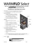
FIELD TESTS:
A. Before Installation of the Add-on Heater:
1. Ensure that the burner does not cycle due to repeated operation of the furnace’s high limit control.
2. Determine whether stabilized outlet air temperature during burner operation is below 150
°
F (66
°
C) in the main outlet duct. If it does exceed 150
°
F (66
°
C) make the following adjustments to the Ventilation System in progressive steps:
Note: In most cases, only steps a) & b) will be necessary.
MOTOR
MOTOR PULLEY
BELT
FAN PULLEY
FAN BLADES a) Check if filters are clogged; b) Check if fan blades are clean. If not, remove the blower from its compartment and clean with a brush; c) Adjust the motor pulley to increase its diameter; d) Change the fan pulley for a smaller size; e) Change the motor pulley for a larger size; f) Change the motor and make sure that the fan control and wiring are adequate.
Note: If steps c), d) & e) are necessary, make sure that the existing motor is adequate: The current drawn must not exceed the nameplate specifications.
Important: The blower must not be changed. If the system cannot provide sufficient airflow after
changing the motor, do not install the add-on heater in that furnace.
B. After Installation of the Add-on Heater:
1. Ensure that the burner does not cycle due to repeating operation of the furnace’s high limit control.
2. Ensure that stabilized outlet air temperature during burner operation does not exceed 160
°
F
(72
°
C) in the main outlet duct.
3. Run burner to ensure that the blower starts soon enough to prevent the manually resettable temperature limiting control on the Add-on Heater from tripping.
4. Operate the Add-on Heater to ensure satisfactory operation without overheating.
Note: Where a cooling coil is present, additional checks should be made to ensure adequate airflow exists for cooling system operation.
Page 4
MECHANICAL SECTION
A. Product Inspection
1) Inspect the carton and heater and report any damage at once.
NEVER INSTALL A DAMAGED HEATER
2) Content of carton:
One plenum heater and baffles. Modulating models include a plenum temperature sensor.
3) File claim with shipping company if shipment is damaged.
B. Installation Instructions:
«
Cautions
»
- The installation, location, position and orientation of the add-on heater must conform with the following:
1) This heater must be installed downstream of the furnace in the warm air plenum.
2) This heater must be installed downstream of the furnace safety limit control.
3) No deformation, removal or displacement of any part of the furnace is permitted.
4) The position of the add-on heater must be as indicated on the front of the heater control box
(Please see Fig. 1).
5) The heater axis must be in line with the plenum axis.
6) Do not install heater from top or bottom of duct. (Please see Fig. 2).
7) Always check that you are not about to cut or drill into any air conditioning or electrical accesory during installation.
SUPPLY PLENUM
DUCT
WRONG
FURNACE
FURNACE
FIG. 1
STANDARD INSTALLATION CLEARANCE
FIG. 2
The heater must be installed in the warm air plenum. A minimum distance of 14 inches is required from the furnace to the elbow, Tee or plenum end take-off of the main supply duct (Please see Fig. 3).
SUPPLY DUCT SUPPLY DUCT
14" min.
FURNACE
2" min.
6" min.
6" min.
FIG.3
Page 5
FURNACE
14" min.
If a cooling coil is installed in the warm air plenum a minimum distance of 1” or 7” is required between the top of the cooling coil and the add-on heater
(depending from which side of the plenum the add-on heater is inserted). (Please see Fig. 4) In both cases, a minimum distance of 2” must be kept between the top of the add-on heater and the elbow, Tee or plenum-end take off of the main supply duct.
FIG. 4
1"
MAIN
SUPPLY
DUCT
7"
COOLING
COIL
FURNACE
SERVICE CLEARANCE AND
CLEARANCE FROM FLUE PIPE
FIG. 5
FURNACE
28" min.
10" min.
FLUE PIPE
The heater may be installed on any available side of the plenum. An installation and service clearance of
28 inches is required from the heater control box to a wall, partition or any other obstruction.
If the heater is installed on the same side as the flue pipe a minimum clearance of 10 inches must be maintained between the flue pipe and the heater control box. (Please see Fig. 5)
Select the plenum side, which offers the most space for installation and service.
VERY IMPORTANT
BAFFLES MUST ASSURE MAXIMUM AIR FLOW OVER THE HEATING ELEMENTS.
- Screw the baffles to bottom flanges of casing, as shown in Fig. 6.
- Cut baffles to size allowing only 1/8” clearance for insertion of heater.
WIDTH OF
SUPPLY PLENUM
BAFFLE
HEATER
ELEMENT
CASING
FIG. 7
PLENUM
FIG. 6
HEATER CONTROL BOX
TOP VIEW OF PLENUM
SHOWING INSTALLED
HEATER AND BAFFLES.
AIR FLOW
All the air from the furnace must pass through the heater element. If the heater element casing is smaller than the plenum the space between the plenum and the element casing must be blocked off with baffles. (Please see Fig. 7)
Page 6
HEATER UP FLOW MOUNTING
Cut out heater opening at a minimum distance of 6 inches from the furnace. Center the opening on the plenum.
Provide slots for insertion if baffles are installed.
(Please see Fig. 8).
Note: The 6 inch dimension from the top of the furnace to the heater opening in the plenum may be increased.
If increased, 14 inch minimum dimensions in Fig. 3 must be increased accordingly.
Slip the heater element into the opening. Make sure that the opening and slots are entirely covered by the heater mounting flanges. Secure the heater to the plenum by means of metal screws
through the pre-drilled holes. For modulating models use angle bracket supplied.
DOWN FLOW MOUNTING
HORIZONTAL MOUNTING
HUMIDIFIER
DO NOT USE PAN & PLATE TYPE HUMIDIFIERS
WITH THE WATER RESERVOIR INSIDE
THE WARM AIR SUPPLY PLENUM.
Only
«
Pressure Differential
» type humidifiers
(preferably a power humidifier) should be used.
If the round inlet duct of the humidifier is connected
on the hot side of the heater, it is strongly recommended
to insert a reducing ring between the round inlet duct of
the humidifier and the opening in the plenum such
that the effective opening for the humidifier will
approximate 4” in diameter. This will reduce the volume
of short-circuited air through the humidifier connection
(Please see Fig. 9).
Page 7
ELECTRICAL SECTION Common to TU and TU-DFC models
1- Disconnect all power sources before opening electrical boxes and working within.
2- Read the nameplate and markings carefully and consult the wiring diagram before you start wiring.
3- Wires and protective equipment should be sized according to the National Electrical Code requirements.
4- Use only wires suitable for at least 75°C. Consult the table “Characteristics” to find the number of feeders required.
5- Connect Thermostat
wires to terminals on heater as shown on wiring diagram.
6- Anticipation. Set the room thermostat heat anticipator at 0.2. Perform start-up and required field tests. Please see Fig. 10 for schematic wiring. (DFC model is shown).
7 Wire heater to furnace as shown on the wiring diagram. For two stage control and
standard plenum heater, remove jumper from terminals 1 and 2 on heater and wire with isolation relay to W2 (second stage) on furnace.
ELECTRICAL SECTION Specific to model TU-DFC
8 - Connect load management control to terminals OP and R on heater.
START-UP for Model TU (mono-energy)
1- Do required fields tests after installation of the Add-on Heater as detailed on page 4.
2- Set the thermostat above the room temperature.
3- Stages will sequence ON at 5 seconds interval.
4- Measure the amperage drawn by the heater and compare it with the one shown on the nameplate. When the thermostat is satisfied, the stages will sequence OFF at 5 seconds interval .
5- Make sure the fan is ON when the heater is energized.
6- Set the room thermostat to the desired set point.
7- Your heater is now ready and functional.
SEQUENCE OF OPERATION for Model TU-DFC (dual-energy)
1- The heater is provided with a two-position mode selector switch. In the “gas / oil” mode the room thermostat will call upon the furnace to maintain the house temperature at the level desired by the user. The “Dual-Energy” mode gives automatic control to the outdoor thermostat or other switching signal for dual-energy control. When the contacts are closed, the electric mode is selected. When the contacts are open, the “gas / oil” mode is selected. A green pilot light indicates the mode in operation.
2- An electronic fault sensor will automatically transfer from one mode to the other in case of failure of one system. A mode is considered to have failed when it is unable to satisfy the room thermostat for more than 2 hours.
Page 8
START-UP for Model TU-DFC (Dual-energy)
1- Do required fields tests after installation of the Add-on Heater as detailed on page 4.
2- The heater is supplied with a built-in 2 position mode selector switch.
( ) position - Heating by means of original furnace.
( ) position - Dual-energy mode.
3- Simulate a heating demand by setting the room thermostat above the room temperature.
4- Switch the mode selector to position ( ) and check if the burner responds to thermostat demand.
5- Switch the mode selector to the dual-energy position ( ). If you jump terminals OP and R the electric mode is selected. The fan will start and the heating elements will come on in sequence at 5 seconds interval. Measure the amperage drawn by the heater and compare it with the one shown on the nameplate. If you disconnect the load management control wires the “gas / oil” mode should be selected.
6- Switch the mode selector to the desired position and set the room thermostat to the desired set point.
7- Your heater is now ready and functional.
Models
Staged Dual-energy Sequences Plenum Heater Breaker
T-5 U-DFC 5
T-10 U-DFC
T-15 U-DFC
T-18 U-DFC
T-20 U-DFC
T-25 U-DFC
T-30 U-DFC
10
15
18
20
25
30
Heating
20.8
2
3
4
4
4
4
41.6
62.5
75.0
83.3
104.0
124.0
Current (Amps)
60
2 x 40
2 x 50
2 x 60
3 x 50
3 x 60
Modulating Dual-energy
T-10 U-DFC-MOD
T-15 U-DFC-MOD
T-18 U-DFC-MOD
T-20 U-DFC-MOD
T-25 U-DFC-MOD
T-30 U-DFC-MOD
10
15
18
20
25
30
2
3
4
4
5
5
41.6
62.5
75.0
83.3
104.17
125.0
60
1 x 60 1 x 30
2 x 50
2 x 60
2 x 60 1 x 30
2 x 60 1 x 40
Page 9
Modulating Plenum Heater Instructions
Installation
Wiring
1. Prior to installation, perform field tests as detained on page 4 of this manual.
2. Install modulating plenum heater in plenum per instructions on pages 5 – 7 of this manual.
3. The DS-600 plenum temperature sensor is installed from 6" to 12" downstream of the plenum heater as show below.
1. Wire unit per instructions on page 8 of this manual.
2. If installing plenum heater with a heat pump system, use a heat pump thermostat and adjustable outdoor temperature sensor/thermostat.
3. If installing plenum heater with a standard heating/cooling system, use a standard heating/cooling thermostat.
4. Wire plenum heater to thermostat and heating/cooling equipment per attached wiring diagram.
5. Wire DS-600 plenum temperature sensor to terminals labelled “WT” on plenum heater PC board.
6. Set desired plenum discharge temperature using adjustable dial on plenum heater PC board. Use reference chart below for set point.
DS-600
Duct Sensor
Plenum Heater
Heat Pump coil
Furnace
#1
Co 43.3
Fo 110
TH 600 Temperature Set Point
#2
45
113
#3 #4 #5 #6 #7
47.7 53.4 56.7 62.8 68.3
118 128 134 145 155
Page 10
TH 600
TE MP E R ATUR E DIAL
SE T P OINT
Modulating Plenum Heater Instructions
Sequence of operation, modulating plenum heater with heat pump
1. When the utility load management control is closed and outdoor temperature is above the set point of the outdoor thermostat, heat pump / electric heat is selected as first stage. With a call for heat, the heat pump will start and provide heat. If the DS-600 temperature sensor senses plenum temperature below the set point of the dial on the plenum heater control board, the plenum heater elements will energize, supplementing the heat provided by the heat pump and modulate to maintain the desired plenum temperature. If the utility load management control is opened, the fossil fuel back up will be selected.
2. When the utility load management control is closed and outdoor temperature is below the set point of the outdoor thermostat, the heat pump will be locked out. With a call for heat, the plenum heater will provide the full heat load and modulate the elements to maintain the desired plenum temperature. If the utility load management control is opened, the fossil fuel back up will be selected.
3. When the heat pump switches to defrost, the fossil fuel back up will be selected and the plenum heater will be locked out. After defrost, the system will switch back to heat pump / electric heat mode.
4. When the utility load management control is open, with a call for heat, the fossil fuel back up will be selected.
5. To manually select fossil fuel mode, switch heat pump thermostat to emergency.
Sequence of operation, modulating plenum heater with standard heating/cooling system
1. When the utility load management control is closed, with a call for heat, the plenum heater will provide the full heat load and modulate the elements to maintain the desired plenum temperature. If the utility load management control is opened, the fossil fuel back up will be selected.
2. When the utility load management control is open, with a call for heat, the fossil fuel back up will be selected.
Page
11
PLENUM HEATER WARRANTY REGISTRATION CARD
Name :
Address :
City :
MODEL NO. :
State :
Date installed :
Zip :
Oil furnace :
❑
Gaz furnace :
❑
Air conditioning :
❑
Heat pump :
❑
Comments / Suggestions :
Warranty Registration Card c/o Thermolec Ltd.
2060 Lucien-Thimens St.
Ville St-Laurent, Montreal
Quebec, Canada
H4R 1L1
advertisement
* Your assessment is very important for improving the workof artificial intelligence, which forms the content of this project
Related manuals

advertisement