advertisement

QUANTUM Qflash Model X
OPERATING INSTRUCTIONS
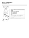
1.0 DESIGNATIONS
1.
Removable Reflector, two positions Normal and Wide angle.
2.
Flash-tube
2A. Modeling Lamp (for Model X2 only)
3.
Bounce Head, Rotates 180º
4.
Swivel Head, Rotates ± 90º
5.
Sensor
6.
Sync Cord Socket (Sync cord purchased separately)
7.
Bracket and Tripod Socket (1/4-20 thread)
8.
Power Cable
8A. Adapter, Power Cable (purchased separately)
9.
Reflector Locking Knob
10. Display Panel
11. Fire Button (Open Flash)
12. Modeling Light Button
13. Mode Button
14. Set Button
15. Up Button
16. Down Button
17. Option Button
18. Earphone Jack
19. Accessory Jack
20. Bracket Mounting Assembly:
Knob, Screw and Mounting Pad
21. Earphone
22. Diffusing UV Filter Kit (QF64)
2.0 SPECIFICATIONS
Angle of
Illumination
Guide Number @ ISO
Reflector Position Horizontal Vertical 200 WS
100
400 WS
Normal
Wideangle
Position
55º
70º
55º
70º
160 ft.
130 ft.
50M
40M
220 ft.
180 ft.
68M
56M
Diffuser/Normal or Wideangle
Barebulb
(no reflector)
90º
360º
90º
180º
90 ft. 27M
-
120 ft.
-
38M
-
Sensor: Acceptance Angle 25º
Power: 200 or 400 watt-seconds (depends on pack)
3.0 WARNINGS!
IF ANY OF THE FOLLOWING WARNINGS ARE VIOLATED, SERIOUS INJURY OR DAMAGE
MAY RESULT:
OPERATE ONLY WITH A FLASH-TUBE IN THE SOCKET.
COMPLETELY DISCONNECT THE POWER PACK BEFORE CHANGING THE
FLASH-TUBE.
NEVER TOUCH THE FLASH-TUBE SOCKET WITH METAL OBJECTS.
DO NOT OPEN THE FLASH UNIT. DANGEROUS HIGH VOLTAGE INSIDE.
(Refer all repairs to qualified Quantum Service Dept).
NEVER CONNECT A QFLASH AND ANOTHER TYPE OF HEAD (NORMAN, LUMEDYNE
ETC.) TO THE SAME POWER PACK. USE SEPARATE POWER PACKS FOR EACH TYPE
HEAD.
TURN POWER PACK OFF WHEN CONNECTING OR DISCONNECTING POWER CABLES.
USE ONLY QUANTUM ACCESSORY AND ADAPTER CORDS.
DO NOT CONNECT TO A POWER PACK RATED HIGHER THAN 400 WATT-SECONDS.
OTHERWISE YOU WILL DAMAGE QFLASH AND VOID ITS WARRANTY.
4.0 SETTING UP THE Qflash
COMPLETELY DISCONNECT THE POWER PACK BEFORE CHANGING THE FLASH-TUBE
OR MODELING LAMP.
4.1 CONNECTING THE FLASH-TUBE AND MODELING LAMP
Connecting the modeling lamp:
Plug in the modeling lamp first. Orientation is not important.
Note: the modeling lamp must be inserted before the flash-tube.
1. Remove lamp from box and plastic bag.
2. Do not touch the bulb surface with bare hands. (Handle with tissue paper.)
3. If bulb surface shows signs of fingerprints or dirt, clean carefully with alcohol.
4. Handle with care during use as impact will severely shorten lamp life.
Connecting the flash-tube:
1. Match the numbers (1, 2, 3, & 4) on the flash-tube base with the corresponding numbers on the flash-tube socket. Push the flash-tube in until it is properly seated inside the flash socket.
NOTE: Replace the flash-tube only with a Quantum type QF32 or QF32uv. Other types will not provide proper exposure or may not work at all.
Match numbers (1, 2, 3, & 4) to the flash tube socket.
4.2 SHOOTING BARE BULB IN AUTO OR TTL MODE
When shooting "bare bulb" in Auto or TTL Mode, you must NOT illuminate the Qflash sensor or the camera lens with light directly from the flash-tube.
This orientation is very good for Macro (close-up).
This orientation for soft bounce light.
Do NOT use with bare bulb facing the front of the flash.
4.3 CONNECTING THE REFLECTOR
The Reflector can be mounted in two positions: Normal or Wide angle.
Loosen the reflector Locking Knob before connecting or when changing reflector positions.
Gently tighten the knob to secure the reflector in the desired position.
Wide angle: Line up the "W" on the reflector to the top of the flash housing. Slide the reflector in until it stops approximately 1/4" (6mm) further into the housing than when in the Normal
Position.
Normal angle: Turn the reflector to the right or left so that the "W" on the reflector does not line up with the top of the flash housing.
4.4 Qflash DIFFUSING UV FILTER KIT
The QF64 Diffusing Kit consists of a black retaining ring and two translucent diffusing disks.
For a softer lighting effect, use the two diffusing disks supplied. For special color lighting effects, a colored gel can be added.
To add a colored gel, remove the two diffusing disks from the retaining ring.
Cut the colored gel (not supplied) the same size as the diffusing disks.
Insert the colored gel between the two diffusing disks. Insert the disk assembly into the retaining ring. Snap the diffuser onto the reflector.
4.5 BOUNCE AND SWIVEL HEAD
Rotates with a stop every 15º.
4.6 BRACKET MOUNTING
The Qflash can be mounted to a camera bracket using the knob provided. (If the knob interferes with your bracket, or you find that the threads are not long enough for your bracket, a longer 1/4-20 screw is also provided.)
Place the enclosed rubber mounting pad on the bracket as shown in the diagram.
This will provide a stable mounting area for the Qflash.
NOTE: Bracket designs vary between styles and the bracket material can vary in thickness. Always make sure that the mounting knob screws into the Qflash at least
2 complete turns.
4.7 POWERING THE Qflash
TURN POWER PACK OFF WHEN CONNECTING OR DISCONNECTING
POWER CABLES. USE ONLY QUANTUM ACCESSORIES AND ADAPTER
CORDS.
Connect the Qflash power cable to an Adapter Power Cable for your power pack.
Plug the Adapter Power Cable into your power pack.
1. Check Power
If the power pack is not supplying power to Qflash, the message "Check Power" will appear in the display and three warning beeps will sound. It may be necessary to switch to the "fast" recycle mode if your power pack has one. This can also mean it may be time to recharge the batteries.
For Lumedyne models only, "Check Power" will appear even when the power pack is switched to off. After switching to off, disconnect the power cable from the Lumedyne pack.
2. Reset
If the Qflash has to reset itself, the message "Reset" will appear in the display. To resume operation, press any button (except the Fire button) and the Qflash will resume operation.
In the event that the Qflash starts behaving strangely (i.e. does not respond to the push buttons, the display blinks, or the display is incorrect) you can force a reset. Turn the power pack off. Press and hold any button
(except the Fire button) and turn the power pack on again.
NOTE: When any reset has occurred, the film speed and power settings that you have entered will be lost and must be entered again.
For Lumedyne power packs, you must unplug the power cable in addition to (and only after) shutting off the power pack. Otherwise, the battery in the pack will discharge.
DO NOT CONNECT TO A POWER PACK RATED HIGHER THAN 400 WATT-SECONDS.
OTHERWISE YOU WILL DAMAGE THE Qflash AND VOID THE WARRANTY.
4.8 SYNC CONNECTION
There are three ways to connect the Qflash to the camera sync.
1. Connect a standard household two-prong sync cord (not supplied with model QFXUS) to the sync connector on the Qflash.
2. TTL Adapter; the sync is provided by the adapter.
3. QF53 Hot Shoe Sync Adapter provides sync from hot shoe.
4.9 HOW TO CONNECT A RADIO SLAVE TO YOUR Qflash/TTL SETUP
1. Connect the Radio Slave Sender to the Qflash sync output.
For Radio Slave 4/4i, use Quantum Cord # 540
For Radio Slave 2, use Quantum Cord # 541
These two cords are available from your Quantum Dealers.
2. The above setup will work with:
QFT/QFT2 serial numbers A6300 and above, and with all QA and QB serial numbers
QFX/QFX2 serial numbers A6325 and above, and with all QA and QB serial numbers
5.0 BASIC Qflash OPERATION
The following section explains the basic operation of the Qflash, when used as a single unit. Available modes are Manual, Automatic, TTL, Program, or Strobo. To change from one mode to another:
1. Press Mode button. Mode will blink.
2. Use Up or Down buttons to change the mode.
5.1 MANUAL MODE
Power Pack Calibration
You need to set Qflash to the power pack rating so that calibration is correct for manual mode.
1. Select manual mode.
2. Push the set button three times until "2" or "4" blinks.
3. Use either the up or down button to choose between "2" = 200 watt-seconds and "4" = 400 watt-seconds.
4. If you have a 400 watt-second pack you can use it at 1/2 power and set Qflash to 200 watt-seconds (Man
2).
Changing Manual Power Setting
1. Push Set button once. Manual power setting on display will blink.
2. Use Up/Down buttons until desired setting appears in the display. The manual power setting can be adjusted from 1/1 to 1/64 in 1/3 stop increments. Available power settings: 1/1, 1/1-, 1/2+, 1/2, 1/2-, 1/4+,
1/4, 1/4-, 1/8+, 1/8, 1/8-, 1/16+, 1/16, 1/16-, 1/32+, 1/32, (1/32-, 1/64+, 1/64 available for Man 4 only).
NOTE: Flash duration shown is for reference only and does not indicate shutter sync speed.
When using Qflash X with a power pack set to 200 watt-seconds, you may shoot at your camera's fastest recommended shutter speed, up to 1/500 (leaf shutters) or 1/250 (focal plane). For 400 watt-seconds we recommend maximum shutter speeds of 1/250 (leaf shutter) and 1/125 (focal plane).
Changing Filmspeed
1. Push the Set button twice. The flash duration will be replaced by filmspeed. Note that the filmspeed display is blinking.
2. Use Up/Down buttons until desired filmspeed appears in the display.
5.2 AUTO MODE
Changing F/number
1. Push Set button once. The "F" in the f/number display will blink.
2. Use Up/Down buttons until desired f/number appears in the display. The f/number can be adjusted in 1/3 stop increments. Changing the filmspeed changes the available f/numbers.
The Qflash will never let you choose an impossible setting (e.g. iso 12 f/32). The Qflash is self adjusting.
Available f/numbers (iso 200) are: 2.0, 2.0+, 2.8-, 2.8, 2.8+, 4.0-, 4.0, 4.0+, 5.6-, 5.6, 5.6+, 8.0-, 8.0, 8.0+,
11-, 11, 11+, 16-, 16, 16+, 22-, 22 ,22+, 32-, 32 (+, - represent +1/3 or -1/3 stop increments).
3. The flash distances are calibrated to the pack's power setting (200 or 400 watt-seconds). The flash distance is only a guide and depends on subject, f/#, reflector position and power pack. Distance ranges displayed are for Normal reflector position.
When using the reflector in the Wide Angle position, flash range is 80% of "Normal" range shown in the
display. When using the diffuser, flash range is 60% of "Normal". The reflector position, wide or normal, makes no difference when using the diffuser.
Changing Filmspeed
1. Push the Set button twice. The filmspeed display will blink.
2. Use Up/Down buttons until desired filmspeed appears in the display. Note that flash distance changes as filmspeed changes. The f/number may also change to keep you in the allowable range of the Qflash.
5.3 TTL MODE
TTL mode is used with all of the Quantum TTL adapters. These optional adapters allow the Qflash to be used with many popular cameras in TTL mode. The TTL instruction booklet has additional details. For a list of available TTL adapters consult the latest Qflash literature, our web page, or your Quantum dealer.
5.4 STROBOSCOPIC MODE
Changing Strobo Frequency
1. Push the Set button once. Frequency setting on display will blink.
2. Use the Up/Down buttons until desired frequency appears in the display. Note the power setting and the number of flashes will change to display the maximum allowable settings.
Changing Number of Flashes
1. Push the Set button twice. The # in front of the count will blink.
2. Use the Up/Down buttons until the desired number of flashes appears in the display.
Changing Strobo Power Setting
1. Push the Set button three times. The dash in front of the power setting will blink.
2. Use the Up/Down buttons until the desired power setting appears in the display.
Changing Power Pack Setting
See Manual Mode.
6.0 FEATURES OF THE Qflash
6.1 FLASH READY
One beep will sound if speaker ( ) is on.
6.2 EXPOSURE INDICATORS (Auto &TTL Mode)
The exposure indicators will come on and blink for approximately 3 seconds after a flash. If the speaker is turned on then a warning will sound three beeps if the exposure is Under or Over. If the exposure is good, one beep will sound when the flash is ready, and the OK will display.
If quiet operation is desired, plug in the earphone or turn the speaker off by using the Speaker Button ( ).
Over-Exposure Indicator
This type of indicator is a new feature for a flash unit. An automatic flash unit's distance is limited to a minimum, as well as to a maximum, distance in which it can provide a correct exposure. Other flash units only tell when the flash exceeds the maximum range, and they do not accurately specify the minimum range under which the flash will over-expose.
Qflash will signal when either the minimum or maximum ranges are exceeded.
6.3 BACKLIT DISPLAY
The Qflash is equipped with a lighted display for operation in dark areas. Whenever any of the push buttons are used, or when an Over, Under or OK exposure indicator appears, the display will light for a brief period.
6.4 MEMORY
The Qflash has a memory which retains your settings, even when the power pack has been turned off. The settings will remain in memory for about 1 day after the Power Pack has been turned off.
6.5 FEET TO METERS (METERS TO FEET)
1. Manual or Auto mode only.
2. Push Set button and hold.
3. Push Mode button. Display will change.
4. Release both buttons.
6.6 MODELING LIGHT
Push the the light button once to turn on the modeling light for 5 seconds, or push the light button twice for a
10 seconds duration. Push the light button a third time and the modeling light will turn off.
6.7 NOTE ON CALIBRATION CHECKS
When checking the calibration of Qflash with a flash meter use reflected light readings for Auto mode and
TTL. The Qflash sensor, like all automatic flashes and TTL exposure controls, reads reflected light. The reflected light reading takes into account the subject's effect on the light reading and can be quite different from an incident flashmeter reading.
When checking the calibration of Qflash in Manual mode, take incident exposure readings. Manual settings of flash units are based on Guide Numbers which do not take into account the subject's effect on light.
7.0 REMOTE SENSOR OPERATION
Quantum Instruments makes a Remote Sensor Module, QF21 (optional), for the Qflash. This module controls the light output of the Qflash from a remote location. This can be useful for example, when aiming the Qflash
into an umbrella. Once the Remote Sensor Module is connected to the Qflash the Auto mode disappears and is replaced by SENS mode. All other modes remain unaffected.
The Remote Sensor can be mounted to the camera's hot-shoe or to a bracket (bracket mounting requires a sync cord, sold separately).
The Remote Sensor comes with a 3 ft. (1m) cord, and can be extended using a 20 ft. (6m) long QF-51 control extension cable. The remote can be extended up to 100 ft. (30m).
7.1 SENS MODE
8.0 MULTIPLE Qflash OPERATION
The following section explains using two or more Qflashes connected together with a cable, to create many types of lighting set-ups. In a multi-flash set-up the operation of Qflashes set to Manual or Strobo modes remains unchanged from the basic operation (Section 5.0). TTL operation remains unchanged as long as no
Qflash is in Auto mode. Several features become available when one or more Qflashes are in Auto mode.
Some examples are shown in this section. (For best performance connect a separate Power Pack to each
Qflash.)
8.1 TWO Qflash IN TTL MODE
This can increase power and/or create multiple light sources with TTL control.
Accessories needed: One Control Cable QF50, one "Y" Module QF52, and one TTL Adaptor.
8.2 TWO Qflash IN AUTO MODE
This allows you to control main/fill ratios by setting different light outputs for each Qflash (e.g. f/8 on one, f/5.6 on another) which controls its own light output independently.
Accessories needed: One Control Cable QF50 and one sync cord.
8.3 ONE Qflash IN AUTO, ONE IN SLAVE MODE
With one Qflash in Auto Mode, the TTL mode of the other unit is changed to Slave mode. The "Slave" unit's light output will be controlled by the Auto unit. Use this set-up when you want more light than available with one Qflash, or when you want light from two directions, controlled by the Qflash near the camera, for example.
Accessories needed: One Control Cable QF50 and one sync cord.
8.4 TWO Qflash IN AUTO MODE AND ONE OR MORE Qflash IN SLAVE MODE
This set-up can be used for multiple lighting and to control the main/fill lighting ratios. Power can also be increased up to 150 WS for each Qflash used.
When two Qflashes are set to Auto Mode, only one Qflash will control any additional Qflashes set to Slave
Mode. The Qflash which has control over the Slave unit(s) will display the normal "Auto" mode; any other
Qflash will display "auto" with a lower case "a".
Accessories needed: Two Control Cables QF50, one "Y" Module QF52 and one sync cord.
8.5 CHANGING THE Qflash THAT CONTROLS THE SLAVE
Push the Mode button on the Qflash in "Auto" mode until "auto" appears. The Qflash which was in "auto" mode will automatically change to "Auto" once it becomes the only Qflash in Auto mode.
Accessories needed: Two Control Cables QF50, one "Y" Module QF52 and one sync cord.
8.6 MISCELLANEOUS MULTI-FLASH INFORMATION
The Rdy's of all flashes connected in a multi-flash setup will appear on the displays when all the flashes are ready. The speakers (on/off) are controlled by the individual Qflashes.
For additional Qflashes added to the sample set-ups shown, one Connecting Cable and one "Y" Module will be required. Any combination of Auto, Manual, TTL/Slave, or Strobo modes is possible.
ADDENDUM
USER ADJUSTMENT OF AUTOMATIC MODE LIGHT OUTPUT ON QFLASH
Your Qflash has been factory calibrated, however it is possible to only adjust the automatic mode light output.
Using a miniature screwdriver, reach into the adjusting port and turn the screw head to the left to increase light output or to the right to decrease light output.
advertisement
* Your assessment is very important for improving the workof artificial intelligence, which forms the content of this project
Related manuals
advertisement