advertisement

Video wall
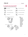
4-1. Precautions when moving and handling
Please adhere to the warning signs printed on the box.
Precaution
Model:
47WV30MS
47WV30BR
47WV30BS
47WV30-BAAM
47WV30-BAAL
47WV50BR
47WV50MS
47LV35A
55WV70BS
55WV70MS
55WV70MD
55LV35A
55LV77A
55LV75A
23
Precaution when Handling
It is advised to move the set as a team of at least 2 persons.
When you move the actual set, please use one hand on grabbing the handle
and the other support under the set.
CAUTION
This way up/ Fragile/ Keep away from rain/ Stacking limit 4.
24
Causes & Phenomena of the Line Defect
[ Line defect picture ]
[ External damage]
The line defect could occur on your set if you strike on the edge of the set.
LOG (LINE ON GLASS) DEFECT
If there has been a shock on Module Left/Top Corner, then you might see at the Left/Top
LOG Crack or Horizontal Line Defect
COF (CHIP ON FILM) DEFECT
Shock on Module Top Side Top COF Crack
Vertical Line Defect
Shock on Module Left Side Left COF Crack
Horizontal Line Defect
25
Do not Drop / Collide & Install with enough airflow
Be careful not to drop / collide the sets with the floor or with each other.
Ensure that you Install in a space with enough airflow
Panel
Panel
26
4-2. Installing the Product
Cut Packing Strap of the Box. Cut Tape on the Box.
Open the Box and remove the top packing.
Remove the Upper Box.
Open the Poly Bag. Undress the Poly Bag.
27
Lift up the Set using the SIDE/BACK Handle. Remove Bottom packing when lifting up the Set.
With one hand under the set and the other hand grabbing the set, move the set.
Lay the back of the Set down on the table.
28
Use the cushion or Pad when you lay the face of the Set downward.
Connect IR receiver to use remocon. And then, connect power code.
29
Remove L-brackets before Installation
Remove the L-brackets from each corner of the monitor before installing it.
NOTE
Keep the removed L-brackets and use them when moving the monitor later.
CAUTION
When you connect Monitor sets for multivision, you may find that the screen
color is not the same across all the Monitor sets. If you want to adjust
the screen color manually, please refer to the Installation Manual.
When you install multiple Monitor sets onto a wall, attach the IR Receiver
to all the sets, or use an RS-232C cable to connect them and then attach
the IR Receiver to the first set.
30
4-3. Tiling Displays : How to Join Sets - Installing Set 1
Example of 2 x 2 tiling
The numbers assigned in this example (#1,#2, #3, #4) are used to demonstrate the
installation procedure to ensure that it is easy to follow. These numbers have nothing to
do with the Set ID that is used to operate the remote control.
Set the guide bracket into the bracket groove using screws and mount the set to the wall
mount plate or the wall.
[ For 47WV30 ]
The wall mount plate is shaded in gray in the illustration to help you see it.
NOTE
LG recommend that the Tiling Display is used for Video Wall product
31
4-3. Tiling Displays : How to Join Sets - Installing Set 2
Join Set 2 to Set 1 using the guide brackets on the top side of Set 1 and mount the two
sets to the wall mount plate or the wall.
Remove the guide brackets after mounting the sets.
The sets joined with the guide brackets
<Rear view of the set with the wall mount plate>
The sets after removing the guide brackets
32
How to remove the guide brackets
Unscrew the guide bracket screws from the rear of the set and remove the guide brackets.
Once the screws are removed, the guide brackets will drop. You need to remove them
through the gap on the sides of the set.
This can be done only when there is enough space between the set and the wall mount
plate or the wall to unscrew the screws. (Please check whether there is enough space
to remove the screws before fixing the guide brackets.)
Removing the guide bracket through the side gap
33
4-3. Tiling Displays : How to Join Sets - Installing Set 3
Fix the guide brackets to Set 3 following the steps above, and loosely mount the set to
the wall mount plate or the wall.
Minimize the space between the sides of the sets using the U-shaped fixture.
When the sets are firmly mounted to the wall, remove the U-shaped fixtures.
34
4-3. Tiling Displays : How to Join Sets - Installing Set 4
Loosely mount Set 4 to the wall mount plate or the wall and minimize the space
between the sets using the U-shaped fixtures.
When Set 4 is firmly mounted to the wall, remove the U-shaped fixtures.
Remove the guide brackets. See <How to Join Sets - Installing Set2,3>.
Now the 2 x 2 tiling is complete.
You can tile in various combinations, such as 3 x 3.
Set 4 joined to the rest of the sets
(2 x 2 tiling)
CAUTION
The guide brackets for tiling should only be used to join sets and should be
removed once they are joined.
The guide brackets should only be used as the assisting tool when tiling sets.
The load applied to each set should be supported by the wall mount plate or
the wall using a VESA wall mount (800 x 400).
(Each set must be firmly mounted to the wall mount plate or the wall.)
The guide brackets must be removed once the sets are joined. When joining
the sets without removing the guide brackets, extra caution is required to
prevent damage due to the set weight.
The U-shaped fixtures must also be removed after mounting the set to the
wall mount plate or the wall.
35
4-4. How to Daisy Chain Monitors
RGB Cable
15-pin D-Sub Signal Cable (Max 3m)
DVI Cable
DVI Cable (Max 3m)
NOTE
"Input signal may be degraded or lost when multiple monitors are connected.
For DVI, in general, up to 12 monitors can be connected via the DVI Out port
(at the recommended resolution) if the signal is stable and there is no cable loss.
(If you want to connect more than this number of monitors, we recommended that you use
a distributor.)
When the tile mode is configured via DVI cables, only the monitor that receives first signals can
play HDCP-encrypted content. (The DVI Out port does not support HDCP).
If the signal cable between the product and your PC is too long, make sure to use the DVI (RGB)
booster or DVI (RGB) optical cable.
If input signals are received through the HDMI/DP cable, multiple monitors cannot be connected
via the DVI Out port"
36
DP Cable
In case of 55LV77A, 55LV75A
DP Cable
NOTE
If the signal is stable and there is no cable loss, in general, up to 25 Monitors can be connected
via the DP Out port (at the recommended resolution).
If you want to connect more than this number of monitor, it is recommended to us a distributor.
When the Tile Mode is configured via DP, max. 8 monitors can play HDCP-encrypted content.
If the signal cable between the product and your PC is too long, make sure to use the Booster
or optical cable
If input signals are received through the DVI/HDMI cable, multiple monitors cannot be connected
via the DP Out port.
37
4-5. Function Setting (Multivision Configuration) 1/2
Remote control
IN port
IR Receiver
(example) 2x2 Set
Set ID:1 Set ID:2
Set ID:3 Set ID:4
38
4-5. Function Setting (Multivision Configuration) 2/2
Refer to..
Refer to..
39
4-6. Setting the Installation Menu (1/2)
1
If you press the MENU button on the remote control for more than five seconds,
the main menu appears and then disappears. The input data is also displayed in
the upper left corner of the screen.
2
Press the "0" button four times. Press the OK button.
3
When the Installation Menu is displayed, select the item you want.
40
4-6. Setting the Installation Menu (2/2)
Menu
Signage Mode
Operation
Description
Decide to work all functions of 'Signage Mode Operation' or not.
15Min Force Off
4 hours off
Wake On LAN
Power On Status
Input Source
Change
Menu Display
Turns off the monitor if there is no input for more than 15 minutes.
"No" is the recommended default value setting.
Turns off the monitor if there is no input on the remote control for more than four hours."No" is the recommended default value setting.
Turns on the monitor remotely using LAN.
Total Set ID
DPM
Sets the maximum value for picture IDs.
Enters energy saving mode if there is no input signal.
Software Update Sets whether to use NSU (Network Software Update).
Decide to select working status of Monitor Set when turn on main power.
Decide to change input source or not by setting 'Input Source Change' as
Yes(Change possible) or No(Change impossible).
MENU key does not work if 'Menu Display' is set to No.
OSD Display
Min Volume
Max Volume
Decide to display OSD or not by setting 'OSD Display' as Yes(Mark) or No(No Mark).
Decide 'Min Volume' between changing range 0 to 100.
Decide 'Max Volume' between changing range 0 to 100.
Power On Default
Input Source
Volume
Aspect Ratio
Intelligent Auto
Factory Reset options.
Set whether it is turned on by the set input source or by the last stored input source.
This sets whether to apply the Volume Level or not when the power is turned on.
With the power turned on, you can set the 'Aspect Ratio' option with the pre-defined value.
If the setting is Yes, Display is automatically arranged through resolution size when you change the resolution at the first.
If it is set to No, 'Factory Reset' under OPTION is disabled.
41
Menu
LG IR Operation
Local Key
Operation
Sync Mode
Baudrate
Pivot Mode
Description
Set the remote control.
Decide
On(Work) or Off(Do Not Work).
With single content file from the Elite-w such as a video or an image simultaneously.
Changes the RS232 communication speed for controlling your monitor. It can be set to 9600 or 115200.
Inverts the screen display according to the settings..
The available options are Off, On or Auto.
42
4-7. Setting the Tile Mode
In Tile Mode you can view an image in a larger scale by connecting multiple monitors.
Tile Mode Off: An input image is not enlarged, and the same image is shown on all connected
monitors.
Tile Mode On: An input image is enlarged according to the value in the H. Set Count and V. Set
count fields.
Tile ID
Example: 2 x 2 Example: 3 x 3
When using 9 monitors
43
4-8. Setting the Picture ID (1/2)
Picture ID is used to change the settings of a specific set (display) using a single IR
receiver for multi-vision. The set receiving the IR signal communicates with another
set via the RS232 connector. Each set is identified by a Set ID. If you assign the
Picture ID using the remote control, only displays with the same Picture ID and Set ID
can be controlled remotely.
2X2 Multi-Vision (Total Set ID: 4)
Set IDs are assigned as shown in the picture.
44
4-8. Setting the Picture ID (2/2)
on the remote control. the ON button repeatedly, the Picture ID
cycles through OFF and 1 to 4.Assign the
ID you want.
If you assign the Set ID to each set with multi-vision, and then assign the Picture ID
using the red button on the remote control, the key command is displayed for the set
with the same Set ID and Picture ID. A set with different Set IDs and Picture IDs cannot be
controlled by IR signals.
Refer to the Set ID on page 46 for assigning a Set ID.
The maximum value of the Picture ID can be set in the Total Set ID menu.
Please refer to the Installation Manual for more information on the assignment of a Total Set ID
NOTE
For example, if the Picture ID is assigned to 2, the upper right display (Set ID: 2) can be
controlled by IR signals.
For each set, you can change the settings for the PICTURE, AUDIO, TIME, OPTION, NETWORK
and MY MEDIA menus or the hot keys on the remote control.
If you press the ID OFF (Green) button, the Picture IDs for all sets are turned off
If you then press any button on the remote control, all sets will start working again
The Picture ID function may not work during MY MEDIA operating.
45
4-9. The Heat Distribution of 47WV30
Heated air flows upward
The adjacent area temperature is higher by 4 o
C more than the non adjacent area
When installed as a video wall, the top position product's temperature is to be highest
*Ambient temperature: 25 o
C adjacent area
Non adjacent area
[fig1.Front side view] [fig2.Rear side view]
The top position
The top position product's temperature is higher
than bottom position
The bottom position
46
4-10. Guide for installing the signage to reduce gap
To reduce gap, use the product weight itself & force it to the center
A. Installation Steps
Product Product Product Product
4
B. Installation Guide
[ 2X1 Installation Guide ]
[ 1X2 Installation Guide ]
[ 2X2 Installation Guide ]
* Applied Model : 42WL10, 47WL10
[ gap picture]
47
4-11. White Balance Calibration Instruction
A. Preparation for calibration
A-1. Version Matching of Video Wall Monitor F/W and SuperSign C for Working Compatibility
Models
F/W version
SOC
Micom
Models
F/W version
SOC
Micom
SuperSign C
55LV77A-7BL, 55LV77A-5BL, 55LV75A-7BL, 55LV75A-5BL 47/55LV35A all
55WV40MS
3.24.03 or later
1.14.3 or later
3.00.10 or later 3.00.01 or later
1.19.8 or later
55WV70MD 47WV50BR
8.02.0 or later
47WV30 all
3.01.22 or later 3.00.14 or later 3.10.20 or later
3.02.5 or later 1.17.1 or later 2.05.2 or later
2.1.1.0
NOTE(Very Important!)
If the F/W version is lower than ones above you must update
A-2. Setting for calibration
SuperSign C
RS232C
: RS-232C connection
(1) IR receiver is needed for manual adjustment
(2)
(3) Before calibration, it is necessary to turn on the monitor at least 2 hour.
48
B. Flow Chart of Calibration
1
Calibration
(SuperSign Elite-C)
2 st nd
step
step
Manual Adjustment
(SuperSign C or
IR Remote control)
1) Recommendation for values
START
Measure
You can check the brightness and color temperature
Calibration
Measure
To check calibration result
Check
White Balance
Bad
Good
Manual Adjustment
END
Gamma
Create Gamma Table
Pattern Level
47WV50BR
55WV70BS
55LV35A all
55LV75A all
Luminance
47WV50MS
55WV70MS
55LV77A all
Color Temperature
2.2
Enable
9
400
600
10000K
About the way of 2 nd
step, refer to Appendix.
Duplication function is not recommended.
You can improve accuracy of Color Temperature with 33 level
49
C. Appendix 1 : Manual Adjustment guide
C-1. Two ways of manual adjustment
1) Manual Adjustment with SuperSign C
> You can adjust white balance manually by changing R/G/B gain
> Except some special cases such as broadcasted video wall, You should not change R/G/B offset value. It may cause side effects to the whole color level.
Note) In case of white balance adjustment at broadcast station, it can be needed to control R/G/B offset
because it should be adjusted based on color temperature of broadcast camera. )
Warning (Very Important!)
If the set the gain value to 192 or higher, some color may not be rendered properly. Because the max gain value is 192
Recommend changing gain value under 3 steps per each color, if you want to change
50
Case A) Pressing hot key of new remote controller
Case B)
of
installation menu by using any kinds of
remote controller remote controller
Press the [MENU] button for more than five seconds
The input data is displayed in the upper left corner of the screen
Press the [ 0 ] button four times.
Press the [OK] button
Item
New remote controller applied
Hot key availability
(Case A)
Entering installation menu
(Case B)
55LV75/77A 47/55LV35A
Yes
Yes
Yes
Yes
Yes
No
47WV50
Yes
Yes
Yes
55WV70
No
No
Yes
47WV30
No
No
Yes
51
C-2. Recommendation test pattern (in case of 3x3)
1) The test pattern needs to be moved and scaled up and down for comparing
Check!
* Check point: White and gray color
Check!
Check!
1 st Step
Check!
2 nd
Step
52
C-3. Calibration pattern
1) Test Patten
C-4. R/G/B gain manipulation
Symptom
Action
Greenish case
Reduce Green gain or
Increase Red & Blue gain
Yellowish case
Reduce Red & Green gain or
Increase Blue gain
Reddish case
Reduce Red gain or
Increase Green & Blue gain
Symptom
Action
Magenta color case
Reduce Red & Blue gain or
Increase Green gain
Bluish case
Reduce Blue gain or
Increase Red & Green gain
Cyan color case
Reduce Green & Blue gain or
Increase Red gain
53
D. Appendix 2 : Troubleshooting
Problem
Did Calibration fail?
Resolution
Refer to the Version Matching chart.
And If needed update both SOC(Flash) and Micom to the latest version.
Is there any abnormal working at
SSC or monitor?
(e.g : R/G/B gains are over 192 after calibration or SSC is hang-up or terminated abnormally and so on.)
Is the white color different between video wall screens after calibration?
There is color mismatching after calibration.
Did you use Duplication function?
If the result is same, please adjust manually.
Note) If you set color temperature as over 11000, working.
More than 2 screens may have individual color and brightness uniformity, this lack of uniformity could make them to look different.
So proceed the manual adjustment white balance more correctly.
There could be problem when you use Duplication function because of the uniformity of panel.
If you used Duplication function to reduce processing time,
Calibration pop up message
Set to the maximum luminance
Set to the minimum luminance
Fail to adjust color temperature
Please manually adjust Gain Value
Fail to change backlight
Fail to change the mode
Fail to set RGB Gain/offset
Fail to find sensor error
Resolution
Reduce the target luminance level to a proper range.
Set ISM mode to normal.
Increase the target luminance level to a proper range.
Adjust manually.
Set both Energy saving and Easy Brightness of Picture menu to off.
Check the control connection such as RJ45, RS232.
Adjust manually.
Check the control connection such as RJ45, RS232.
Make sure your sensor is connected well to the unit being calibrated.
54
E. Appendix 3 : Auto Set ID Guide
(Only 47LV35A, 55LV35A, 55LV55A, 55LV75A, 55LV77A)
E-1. Two ways of Auto Set ID
1) By using SuperSign C
1
Select the 1st monitor daisy chained by RS-232C and Click the Auto SET ID button
2
3
Monitor executes Auto Set ID.
Reassign Set ID number in SSC like below
2) by using user remote controller
1
2
E-2. Before & After Auto Set ID
Before) Connect IR Receiver and RS232
Cable such as shown in the following picture.
After) Set ID of all sets is sequentially set by
RS232 connection order automatically.
55
4-12. How to prevent the panel falling out
the panel (Especially, center of the bottom of panel)
If you touch it strongly, the panel may go into inside of the module
Whenever you move the set, please try to use the handle on the rear side
If you move the set without using the rear handle, be careful not to touch the front of
Panel got into the inside of module (Defect point)
If the panel has got into the inside of the module, please refer to below guide
Example of 55LV75A
1
Lay the back of the set down on the table
2 Loosen the screws from the near of defect point (5 screw or more)
Defect point
Rear side
3 Lift the set using the back handles(4ea) and shake the set up and down slowly
4 Check panel be in good or not and then joint screw again
56
advertisement
* Your assessment is very important for improving the workof artificial intelligence, which forms the content of this project
Related manuals
advertisement