advertisement

Quasar Gen II CB-6208 Bullet IP Camera Quick Installation Guide
Initial Configuration
1. Prepare the camera:
Remove the camera from the package.
2. Attach an Ethernet cable:
a. Connect one end of a Cat 5 Ethernet cable to the camera’s Ethernet port, and the other end (RJ45) to a Power Sourcing
Equipment (PSE) device, such as a PoE switch. b. Verify that the LED on the port is green, indicating a good network connection. A yellow LED flashes when there is network activity.
NOTE: The camera IP Address and the subnet mask IP Address are automatically supplied by the DHCP server.
TIP: A camera setup adapter, such as Veracity Pinpoint, can be used to connect a laptop directly to the camera using PoE.
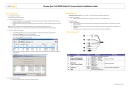
3. Set the camera’s IP address:
a. Open the DNA application (version 2.0.4.3 or later). Select the unit requiring IP assignment. See figures below. b. To open the DNA Assign IP screen, do one of the following:
Select the unit, right-click the mouse, and select the Assign IP option
Select the Assign IP button from the toolbar
Site Installation
Operating temperature range: -40°C ~ 50°C (-40° ~ 122°F), 0-95% relative humidity (non-condensing)
1. Mount the camera:
a. Install the Quasar Gen II bullet camera according to the camera’s User and Installation Guide.
2. Attach cables:
Using the attached cables: a. Plug the Cat 5 cable into the camera Ethernet port and plug the other end of the cable into a network switch or an IEEE
802.3af PoE device. b. If applicable, connect the Alarm In, Alarm Out, Audio In and Audio Out terminals to external devices. See the figures and table below. c. If applicable connect an external power source to the terminals. See the figure and table below.
Camera Connectors
c. If your network does not have a DHCP server, enter the IP Address, Mask (Netmask) and Gateway values in the dialog box displayed below. d. Click Update and wait for OK status to be displayed. The IP address has been assigned.
4. Disconnect the cable:
a. Disconnect the Ethernet cable. The camera is ready for mounting.
No
1 RJ45
2
Cable
Power (12VDC/24VAC)
(3-pin Terminal Block)
3
Alarm I/O
(4-pin Terminal Block)
4 Audio I/O
5 BNC
Pin
-
1
Definition
For network and PoE connections
DC 12V − AC 24V 1
Remarks
Power connection 2
3
Reserved GND
DC 12V + AC 24V 2
Alarm In − 1
2
3
4
Alarm In +
Alarm Out −
Alarm Out +
Green Audio Out
Alarm connection
Two-way audio transmission
Pink Audio In / Mic In
- For analog video output
CB-6208_QIG_Oct13_2014
Adjusting and Framing-Up the Camera View
1. Camera Access and Login:
Access the camera in one of the following ways: a. If using the DNA application, click the DNA icon shortcut menu, and select Browse.
. In the Discovery List, click to select the camera, right-click to open the b. If using a web browser, enter the camera’s IP address in the address bar.
2. Before logging into the camera:
The client application is automatically installed when you connect to the camera through your PC/workstation web-browser for the first time. Before accessing the camera, ensure that ActiveX controls can be downloaded by (a) changing the ActiveX controls and plug-in settings or (b) setting the Internet security level to default. For further details, refer to the camera’s User and Installation
Guide.
ActiveX Controls and Plug-in Settings Internet Security Level
Step 1: Start Internet Explorer (IE 8, 9, 10, or 11).
Step 2: Select Tools from the main menu of the browser. Then click Internet Options.
Step 3: Select the Security tab and click Internet.
Then click Custom level to change ActiveX settings.
Step 4: Set all ActiveX controls and plug-ins settings to Prompt or Enable.
Step 1: Start Internet Explorer (IE 8, 9, 10, or 11).
Step 2: Select Tools from the main menu of the browser. Then click Internet Options.
Step 3: Select the Security tab and click Internet.
Step 4: Click Default level. Click OK to confirm the setting. Close the browser window. Open a new window later to access the IP camera.
3. Camera Login:
See the section titled Initial configuration for instructions on setting the cameras IP address.
4. Login ID and Password:
a. Enter the camera’s IP address in the browser’s address bar and press the Enter key. b. Enter the default user name (Admin) and password (1234).
NOTE: The user name is case-sensitive.
5. Install the ActiveX control:
a. After accessing the camera through the web browser for the first time, a request to install the ActiveX control appears below the address bar. b. Right-click on the information bar, and select Install ActiveX Control… to permit ActiveX control installation. c. In the pop-up security warning, click Install to start downloading the DVPlayer software onto the PC. d. Click Finish when the DVPlayer installation is completed.
NOTE: Before accessing the camera, if you have previously installed an older version of the DVTEL Web Player (DVPlayer) on the PC, use the Windows Add/Remove program to uninstall the existing DVPlayer from the PC. For more information, refer to the camera’s
User and Installation Guide.
Attach in Latitude
1. In the Latitude application, on the sidebar click Physical View.
2. On the Navigation Tree click the System name.
3. Select the Discovery tab and do the following: a. Under Cameras and Encoders, verify that DVTEL Quasar Gen II is selected. b. Click Start. The camera details are displayed in the Discovery table. c. If the camera wasn’t found after running Start, click Discover
Unit Manually. d. In the dialog box that opens, enter the camera’s IP address, select DVTEL Quasar Gen II and click OK.
4. In the Discovery table, right-click the camera, choose Attach, and then click the Archiver name to attach.
5. When finished, click to save.
Models in the CB Series:
Model Number Description
CB-6208-11-I Indoor/outdoor vandal-proof bullet IP camera with motorized lens and infrared IR illuminator
How to Contact DVTEL:
North America: 1-888-DVTel77
Latin America: +52 555580 5618
EMEA: +44 (0) 1494 430240
APAC: +65 6389 1815
China: +86 10 8586 8836
India: +91 (129) 431 5031
ANZ/Pacific: +61 8 8235 9211
For assistance, email us at [email protected]
or visit http://www.dvtel.com/support .
© DVTEL, Inc. All rights reserved worldwide. Printed November 2014
advertisement
* Your assessment is very important for improving the workof artificial intelligence, which forms the content of this project
Related manuals
advertisement