advertisement

Part II, Chapter 17: Overview of Peripherals
17 Overview of Peripherals
L-761e_2
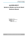
Fig. 17-1. Overview of Peripherals
The phyCORE-AM3517 Carrier Board is depicted in
Figure 17-1 and includes the following components
and peripherals listed in
,
, and
Table 17-3 . For a more detailed description of each
peripheral, refer to the appropriate chapter listed in the applicable table.
Table 17-1. Connectors and Headers
Ref. Des. Description
X9
X10
X11
X12
X13
X14
X5
X6
X7
X8
X1
X2
X3
X4
USB OTG Connector (AM3517 - USB1)
USB Host (AM3517 - USB0)
MMC1 easy access header
Camera easy access header (AM3517 - CCDC)
MMC / SDIO connector (AM3517-MMC1)
CAN connector
WIFI connector (AM3517 - MCBSP1 / UART1 / MMC2)
DVI video connector
Wall adapter input power jack to supply main board power
UART easy access connector (AM3517 - UART2 / UART3)
CPLD JTAG (video bit map programmable logic)
LCD LVDS connector
JTAG interface to AM3517
GPIO expansion connectors
Chapter
© PHYTEC America LLC 2012 48
Part II, Chapter 17: Overview of Peripherals
Table 17-1. Connectors and Headers (Continued)
Ref. Des. Description
X25
X26
X27
X28
X29
X30
P1
X15
X16
X17
X18
X19
X20
X23
X24 phyCORE-AM3517 connectors to SOM
TV Out
Ethernet connector (POE capable)
PHYTEC Camera interface (AM3517 - CCDC)
PHYTEC Camera easy access header (AM3517 - CCDC)
LVDS LCD power and backlight control connector
Loudspeaker connector
MIC in connector
Headphones connector
Line out
Ground test point
Ground test point
UART2 RS-232 connector
LCD TTL connector
UART3 RS-232 connector
Table 17-2. Description of the Buttons and Switches
Ref. Des. Description
S5
S6
S7
S8
S1
S2
S3
S4
S9
S10
LCD video color bit depth control
LCD orientation control
System Reset button
User button 4 (labeled BTN4)
User button 3 (labeled BTN3)
User button 2 (labeled BTN2)
User button 1 (labeled BTN1)
SYS_BOOT 4 & 5 switches
SYS_BOOT 3 & 2 switches
SYS_BOOT 1 & 0 switches
Table 17-3. Description of LEDs
Ref. Des. Description
D25
D26
D27
D28
PoE power available
Power connector power available
User controlled LED 2
Ethernet Link LED
© PHYTEC America LLC 2012
L-761e_2
Chapter
N/A
N/A
Chapter
Chapter
49
Part II, Chapter 17: Overview of Peripherals L-761e_2
Table 17-3. Description of LEDs (Continued)
Ref. Des. Description
D29
D30
D31
User controlled LED 1
User controlled LED 3
Ethernet Speed LED
Chapter
Please note that all module connections are not to exceed their expressed maximum voltage or current.
Maximum signal input values are indicated in the corresponding controller User's Manual/Data Sheets. As damage from improper connections varies according to use and application, it is the user's responsibility to take appropriate safety measures to ensure that the module connections are protected from overloading through connected peripherals.
© PHYTEC America LLC 2012 50
advertisement
* Your assessment is very important for improving the workof artificial intelligence, which forms the content of this project
