advertisement

Device Configuration
* Note: The information fields in the Port Configuration dialog box vary according to the type of port selected.
Port Configuration - General Tab
To view the General tab of the Port Configuration dialog box for a selected port:
Click the port symbol in the Chassis View.
Or
Click the port’s icon in the Tree View. The Port Configuration dialog box opens to the General tab.
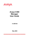
Figure 11. Port Configuration Dialog Box - General Tab
The following table provides a list of the fields in the General tab of the
Port Configuration dialog box and their descriptions:
Avaya C360 Manager User Guide 49
Chapter 3
Field
Port Name
Table 14. Port Configuration Fields - General Tab
Description
The user can define a logical name to the port for ease of use.
Port Type
Port Functionality
Administrative Status
LAG Name
The port type; optionally includes reference to the module to which it is attached and port connector type.
The physical media type of the selected port. If the port conforms to a certain standard
(Repeater, Transceiver, 10BaseT, etc.), this standard is displayed. If the port does not conform to any standard, Private is displayed.
The administrative state of the selected port:
•
Enabled
- The port is enabled and can transmit and receive packets.
•
Disabled
- The port is disabled and cannot transmit or receive packets.
The name of the LAG of which the port is a member. If the port is not a member of a LAG, the LAG Name is not in LAG.
Tagging Mode
VLAN ID
The port’s operation mode regarding VLANs.
The possible modes are:
•
Clear
- Transmits each outgoing packet in untagged format if it belongs to the port’s
VLAN. Otherwise, it discards the packet.
•
IEEE-802.1Q
- VLAN tagging, per IEEE
802.1Q VLAN standard. The port will transmit frames with a VLAN ID of 1 -
3071.
The VLAN number of the port.
50 Avaya C360 Manager User Guide
Device Configuration
Table 14. Port Configuration Fields - General Tab (Continued)
Field
Port Priority Level
Auto Negotiation Mode
Description
The priority level of packets exiting the port or ports on the module. For effective transmission, multimedia packets must be received isochronously (at regular intervals).
To ensure this, you can assign priorities to packets coming out of a port.
Whenever traffic load is extreme and a port cannot accept all incoming packets, packets sent from a port with the highest priority will pass through first. However, a fairness mechanism will allow low priority packets to eventually enter the bus.
Possible values are:
• Regular
• High
The configured state of the Auto-Negotiation protocol between two stations. When enabled,
Auto-Negotiation detects the highest common denominator for communication between endstations, and sets both to the same highest common setting. It also delivers remote link status.
For 10BaseT and 100BaseT ports,
Auto-Negotiation determines the speed and
Duplex Mode of communication between the endstations. For Gigabit ports, Auto-
Negotiation determines the Flow Control setting of the ports.
For more information, refer to Auto-Negotiation in The Reference Guide.
Avaya C360 Manager User Guide 51
Chapter 3
52
Table 14. Port Configuration Fields - General Tab (Continued)
Field Description
Auto Negotiation
Status
The operational state of the Auto-Negotiation protocol between two stations. Possible statuses are:
•
Pass
- The Auto-Negotiation protocol is enabled and a common protocol has been established.
•
In progress
- The Auto-Negotiation protocol is in the process of detecting the communication capabilities of the endstations and setting them to the highest common denominator.
•
Fail
- The Auto-Negotiation protocol was not able to detect the communication capabilities of the end station, or was unable to set them to the highest common denominator.
•
Disabled
- The Auto-Negotiation protocol is disabled.
Duplex Mode
Speed Mode
Flow Control Mode
Operational Status
Fault Messages
The state of communication of the selected port. Possible values are:
•
Full Duplex
- The port can send and receive simultaneously.
•
Half Duplex
- The port can either receive or send, but can not do both simultaneously.
The speed of communication of the selected port. Possible values are:
•
Ethernet
- 10 Mbps.
•
Fast Ethernet
- 100 Mbps.
•
Gigabit Ethernet
- 1000 Mbps.
The state of flow control on the selected port.
The warning level of the selected port.
Possible values are:
• OK
• Warning
• Fatal
A list of fault messages.
Avaya C360 Manager User Guide
advertisement
* Your assessment is very important for improving the workof artificial intelligence, which forms the content of this project