advertisement

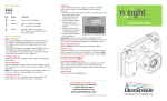
TANDBERG FieldView™ delivers the most innovative solution in mobile video collaboration.
Featuring integrated wireless LAN, high resolution video and audio and the ability to collaborate via instant on-screen annotation— it’s the next best thing to having your experts on the scene.
Its ability to access small spaces enables productivity in areas previously inaccessible by video, allowing organizations to address and resolve issues instantly.
Recording capabilities enable device and PC users to archive material for a later date or collaborate over previously recorded material.
All content can also be extended to an officebased video meeting using a PC with the
FieldView application and H.239 dual stream capabilities.
FieldView
Device
Version 3
User Guide
D14041.02 January 2008
The FieldView Device and the software contained in and used with the FieldView Device is subject to the following notices:
Copyright © 2004–2008 LibreStream Technologies Incorporated.
All rights reserved.
Patents Pending in Canada, the U.S. and other countries.
TANDBERG is a registered trademark of Tandberg ASA. All other trademarks are the property of their respective owners.
Portions include software under the following terms:
_______________________________________________
Live Networks Inc.:
Copyright © 1996–2005, Live Networks, Inc. All rights reserved
This library is free software; you can redistribute it and/or modify it under the terms of the GNU Lesser General Public License as published by the Free Software Foundation; either version 2.1 of the License, or (at your option) any later version. (See <http:// www.gnu.org/copyleft/lesser.html>.)
This library is distributed in the hope that it will be useful, but
WITHOUT ANY WARRANTY; without even the implied warranty of MERCHANTABILITY or FITNESS FOR A PARTICULAR PURPOSE.
See the GNU Lesser General Public License for more details.
You should have received a copy of the GNU Lesser General
Public License along with this library; if not, write to the Free
Software Foundation, Inc., 59 Temple Place, Suite 330, Boston,
MA 02111-1307 USA
A copy of the GNU Lesser General Public License is provided on the product CD in the ‘licenses’ folder. In accordance with section
(4) of the GNU General Public License, copies of Live Networks source code and Librestream modified Live Networks code will be provided upon request from Librestream. To obtain the source code on a CD, please send USD 10 for shipping and handling to:
Customer Services
LibreStream Technologies Inc.
895 Waverley St., Suite 110
Winnipeg, Manitoba
Canada R3T 5P4
Das U-Boot:
Copyright © 2000–2004
Wolfgang Denk, DENX Software Engineering, [email protected].
This program is free software; you can redistribute it and/or modify it under the terms of the GNU General Public License as published by the Free Software Foundation; either version 2 of the License, or (at your option) any later version.
This program is distributed in the hope that it will be useful, but
WITHOUT ANY WARRANTY; without even the implied warranty of
MERCHANTABILITY or FITNESS FOR A PARTICULAR PURPOSE.
See the GNU General Public License for more details.
You should have received a copy of the GNU General Public
License along with this program; if not, write to the Free
Software Foundation, Inc., 59 Temple Place, Suite 330, Boston,
MA 02111-1307 USA.
A copy of the GNU General Public License is provided on the product CD in the ‘licenses’ folder and may also be available at
<http://www.gnu.org/copyleft/gpl.html>. In accordance with section (3) of the GNU General Public License, copies of Das
U-boot source code and Librestream modified Das U-boot code will be provided upon request from Librestream. To obtain the source code on a CD, please send USD 10 for shipping and handling to:
Customer Services
LibreStream Technologies Inc.
895 Waverley St., Suite 110
Winnipeg, Manitoba
Canada R3T 5P45
The following notice is required regarding the MPEG-4 MAE enabled codec: This software module was originally developed by
Microsoft Corporation and also edited by multiple parties in the course of development of the MPEG-4 Video (ISO/IEC 14496-2).
This software module is an implementation of a part of one or more MPEG-4 Video tools as specified by MPEG-4 Video. ISO/IEC gives users of MPEG-4 Video free license to this software module or modifications thereof for use in hardware or software products claiming conformance to the MPEG-4 Video. Those intending to use this software module in hardware or software products are advised that its use may infringe existing patents. The original developer of this software module and his/her company, the subsequent editors and their companies, and ISO/IEC, have no liability for use of this software module or modifications thereof in an implementation. Copyright is not released for non MPEG-4
Video conforming products. Microsoft Corporation and the other originators of this software retain full right to use the code for their own purpose, assign or donate the code to a third party and to inhibit third parties from using the code for non ISO/IEC 14496 conforming products. This copyright notice must be included in all copies or derivative works.
THIS PRODUCT IS LICENSED UNDER THE MPEG-4 VISUAL
PATENT PORTFOLIO LICENSE FOR THE PERSONAL AND NON-
COMMERCIAL USE OF A CONSUMER FOR (i) ENCODING VIDEO
IN COMPLIANCE WITH THE MPEG4-VISUAL STANDARD (“MPEG-4
VIDEO”) AND/OR (ii) DECODING MPEG-4 VIDEO THAT WAS
ENCODED BY A CONSUMER ENGAGED IN A PERSONAL AND
NON-COMMERCIAL ACTIVITY AND/OR WAS OBTAINED FROM A
VIDEO PROVIDER LICENSED BY MPEG LA TO PROVIDE MPEG4-
VIDEO. NO LICENSE IS GRANTED OR SHALL BE IMPLIED FOR
ANY OTHER USE. ADDITIONAL INFORMATION INCLUDING THAT
RELATING TO PROMOTIONAL, INTERNAL AND COMMERCIAL
USES AND LICENSING MAY BE OBTAINED FROM MPEG LA, LLC.
SEE HTTP://WWW.MPEGLA.COM.
About this document: All rights reserved. This document contains information that is proprietary to TANDBERG. No part of this publication may be reproduced, stored in a retrieval system, or transmitted, in any form, or by any means, electronically, mechanically, by photocopying, or otherwise, without the prior written permission of TANDBERG. Nationally and internationally recognized trademarks and trade names are the property of their respective holders and are hereby acknowledged.
Copyright © 2008 TANDBERG
Contact information:
TANDBERG
Philip Pedersens vei 22, No-1366 Lysaker, Norway
Telephone: +47 67 125 125
Fax: +47 67 125 234
Video: +47 67 117 777
E-mail: [email protected]
D14041.02 January 2008
TANDBERG FieldView Device User Guide
Table of Contents
1. The FieldView Device . . . . . . . . . . . . . . . . . . . . . . . . . . . . . . . . . .
1.1. About This Guide . . . . . . . . . . . . . . . . . . . . . . . . . . . . . . . . . . . . . . 1
1.2. What’s in the Box . . . . . . . . . . . . . . . . . . . . . . . . . . . . . . . . . . . . . . 1
1.3. Parts of the FieldView Device. . . . . . . . . . . . . . . . . . . . . . . . . . . . . .2
2. FieldView Device Basic Operation . . . . . . . . . . . . . . . . . . . . . . . .
2.1. Charging the Battery . . . . . . . . . . . . . . . . . . . . . . . . . . . . . . . . . . . 4
2.2. Inserting or Replacing the Battery . . . . . . . . . . . . . . . . . . . . . . . . . . 4
2.3. Calibrating the Integrated Touch Panel . . . . . . . . . . . . . . . . . . . . . . . 5
2.4. Turning Power On or Off . . . . . . . . . . . . . . . . . . . . . . . . . . . . . . . . . 6
2.5. Logging On & Off . . . . . . . . . . . . . . . . . . . . . . . . . . . . . . . . . . . . . . 7
2.6. Inserting and Removing an SD Memory Card . . . . . . . . . . . . . . . . . . 7
3. Answering & Initiating Calls . . . . . . . . . . . . . . . . . . . . . . . . . . . .
3.1. Network Access . . . . . . . . . . . . . . . . . . . . . . . . . . . . . . . . . . . . . . . 8
3.2. Answering an Incoming Call . . . . . . . . . . . . . . . . . . . . . . . . . . . . . . 8
3.3. Initiating (Starting) a Call . . . . . . . . . . . . . . . . . . . . . . . . . . . . . . . . 8
3.5. VoIP Telephone Communication . . . . . . . . . . . . . . . . . . . . . . . . . . . . 9
4. Audio/Video (AV) Functions . . . . . . . . . . . . . . . . . . . . . . . . . . .
4.1. Turning the Video Stream On or Off . . . . . . . . . . . . . . . . . . . . . . . . 10
4.2. Setting the Subject Audio Source . . . . . . . . . . . . . . . . . . . . . . . . . 10
4.3. Using S-video . . . . . . . . . . . . . . . . . . . . . . . . . . . . . . . . . . . . . . . 10
4.4. Turning the Front Light On or Off . . . . . . . . . . . . . . . . . . . . . . . . . . 10
4.5. Adjusting Zoom Levels . . . . . . . . . . . . . . . . . . . . . . . . . . . . . . . . 11
4.7. Telestration (Drawing Lines on the Viewfinder) . . . . . . . . . . . . . . . . 12
4.8. Capturing Still Images . . . . . . . . . . . . . . . . . . . . . . . . . . . . . . . . . 12
4.9. Sharing Images . . . . . . . . . . . . . . . . . . . . . . . . . . . . . . . . . . . . . . 12
4.10. Recording and Playing Videos . . . . . . . . . . . . . . . . . . . . . . . . . . . . 12
4.11. Streaming a Video Recording . . . . . . . . . . . . . . . . . . . . . . . . . . . . 13
5. Viewfinder Features & Display Modes . . . . . . . . . . . . . . . . . . . .
5.1. Controlling the Viewfinder Mode . . . . . . . . . . . . . . . . . . . . . . . . . . 14
6. Menus . . . . . . . . . . . . . . . . . . . . . . . . . . . . . . . . . . . . . . . . . . . . .
6.1. Stream Setup . . . . . . . . . . . . . . . . . . . . . . . . . . . . . . . . . . . . . . . 15
6.2. Checking Status . . . . . . . . . . . . . . . . . . . . . . . . . . . . . . . . . . . . . . 16
6.3. Viewing Local Contacts . . . . . . . . . . . . . . . . . . . . . . . . . . . . . . . . . 16
6.4. Managing Files . . . . . . . . . . . . . . . . . . . . . . . . . . . . . . . . . . . . . . . 16
6.5. Configuration . . . . . . . . . . . . . . . . . . . . . . . . . . . . . . . . . . . . . . . 18
7. Icons . . . . . . . . . . . . . . . . . . . . . . . . . . . . . . . . . . . . . . . . . . . . .
8. Maintaining the FieldView Device . . . . . . . . . . . . . . . . . . . . . . .
8.1. General Recommendations . . . . . . . . . . . . . . . . . . . . . . . . . . . . . . 22
8.2. Display/Touch Screen . . . . . . . . . . . . . . . . . . . . . . . . . . . . . . . . . . 22
8.4. Ergonomic Recommendations . . . . . . . . . . . . . . . . . . . . . . . . . . . . 22
i
D14041.02 January 2008
TANDBERG FieldView Device User Guide
9. Technical Specifications . . . . . . . . . . . . . . . . . . . . . . . . . . . . . . .
10. Safety & Regulatory Information . . . . . . . . . . . . . . . . . . . . . . .
ii
D14041.02 January 2008
TANDBERG FieldView Device User Guide
1. The FieldView Device
The FieldView system provides mobile real-time video conferencing for locations that are usually not accessible with standard video conferencing equipment. This includes locations such as test labs, health care facilities, factory floors, service departments, remote suppliers, inspection areas, customer facilities, and other remote work team locations.
This manual describes the FieldView Device. An Operator at a remote site uses the FieldView Device to communicate with a Client user over a network.
The FieldView Device allows both the Operator and the Client user to:
•
Converse just as they would on a mobile telephone.
•
View and listen to streaming audio/video output in real time.
•
Stream audio and video recordings to the
FieldView Device in real time.
•
Capture and save snapshot images.
FieldView
Application
•
Share snapshot images between the
FieldView Application and FieldView Device.
•
Record and play back video.
•
Adjust the controls (e.g., zoom, focus, draw on the screen).
The FieldView Device allows technical experts and remote operators to jointly view, consult, diagnose and resolve issues by sending high-resolution video, sound and still images through streaming multimedia from the onsite FieldView Device to a FieldView
Application on an office workstation.
1.1. About This Guide
This guide describes how to use the FieldView Device on a system that has already been set up and configured. For information on FieldView Device configuration, maintenance and network or other infrastructure setup, please consult the FieldView System Administration Manual. For information on the FieldView Application software client application, consult the FieldView
Application User Guide.
1.2. What’s in the Box
•
The FieldView Device
•
External power adapter
•
Stylus
•
Rechargeable 2400 mAh Li-Ion battery pack
•
Wrist strap
•
Quick Start Guide
• CD of user guides, end user license, copyright, and FieldView Application software
•
Safety and regulatory information.
For information on additional accessories or for updated FieldView Device documentation, consult the TANDBERG website at
http://www.tandberg.com/.
FieldView Device
1
D14041.02 January 2008
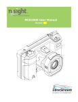
1.3. Parts of the FieldView Device
10
6
4
5
1
3
TANDBERG FieldView Device User Guide
16
17
18
23
24
25
26
19
20
21
22
8
2
7
11
12
13
14
15
28 29
27
9
1 – Streaming on/off
2 – Still image capture
3 – Microphone
4 - LED indicators
5 – Streaming indicator (red =
streaming on)
6 – Light
7 – Camera lens
8 – SD memory card slot
9 – External power connector
10 – Antenna
11 – Headset connector
12 – Audio line in (plug in
external audio source)
13 – S-Video in
14 – USB host interface
15 – Ethernet port
16 – Stylus
17 – Viewfinder
18 – Send button
19 – End button
1.3.1 Control Buttons
Button
Manual
Focus
Display
Mode
Record
Power
Function
Use this button to set the focus manually or to resume automatic focusing. It works in combination with the Zoom buttons. See Focusing on page 11 for more information.
This button cycles through the FieldView Device’s multiple display modes. See Viewfinder Features & Display Modes, on page 14 for more information.
Press this button to start/stop recording to a local Secure
Digital (SD) memory card.
This button controls On/Off/Standby modes. See Turning
Power On or Off on page 6 for more information.
If FieldView Device status is… Power button function
Off Press and release the button to turn power on.
On
Standby
Press and release the button to go to Standby mode.
Press and release the button to enter
Power On mode.
On or Standby Press and hold the button for two seconds to turn the unit off. A shutdown message appears.
Manual
Focus
Display
Mode
Record
Power
20 – Zoom/Manual focus controls
21 – Navigation pad
22 – Speaker
23 - Focus button
24 – Display mode button
25 – Recording On/Off button
26 – Power button
27 – Tripod mount
28 – Battery door
29 – Battery lock
2
D14041.02 January 2008
TANDBERG FieldView Device User Guide
1.3.2. Navigation Pad Buttons
These context-sensitive buttons control audio volume, microphone mute and the front light. They also function as command buttons and directional buttons for the menus.
Button Function
Start or accept call (Send)
Menu Function
OK or Enter
End a call or reject an incoming call invitation
Increase volume
Cancel
Up arrow
Microphone mute Left arrow
Decrease volume
Front illumination light on/off
Enter
Down arrow
Right arrow
Accept
1.3.3. Zoom/Manual Focus Controls
The Zoom buttons are located on the back of the FieldView Device, directly above the Navigation Pad. These allow the Operator to set zoom levels on the camera or to set focus manually (see page 11).
1.3.4. Indicators
Indicator Name Explanation
Power mode indicator Green = On or Standby
Network indicator Green = Network available
Off = Network unavailable
Battery/power indicator
Stream/record
Network connector
Orange = Battery is charging
Off = Battery is charged or power is not connected
Red = streaming/recording on.
Off = streaming/recording off
The Ethernet Port (shown as #15 on the diagram on page 2) also includes an LED indicator:
Yellow On = a wired network link exists.
Yellow Flashing – indicates wired network activity
Yellow Off = no wired network link
The green LED is not used at this time.
1.3.5. Soft Keys
Some screens contain on-screen keys or buttons, e.g., Accept or Cancel on a configuration screen. You can select these buttons by tapping the key with your stylus, or by pressing Navigation pad keys.
Stream/record indicator
3
D14041.02 January 2008
TANDBERG FieldView Device User Guide
2. FieldView Device Basic Operation
2.1. Charging the Battery
New batteries should be charged prior to first use. To do this, plug in the external power adapter and allow the battery to charge until the orange battery indicator extinguishes (up to eight hours). The internal battery charger will shut itself off to prevent overcharging once the battery is fully charged.
Note that the FieldView Device shuts itself off when battery power is low.
•
If the unit is on, and an Operator is using it in an active call, a warning message appears so that the Operator has time to plug the FieldView Device in to the external power adapter, or end the call before the FieldView Device shuts off.
•
If the unit is in Standby, it simply shuts itself off.
•
If the unit is off, it cannot be started when the battery is low.
To check current battery levels, press the Display button once and check the
Session information at the bottom of the Viewfinder. See page 14 for more information on Viewfinder and Display modes.
2.2. Inserting or Replacing the Battery
Important: Before using this device for the first time you must install and charge the battery. Here’s how (refer to figures at right):
1. Open the battery compartment and insert the battery until it clicks into place and is flush. It only fits one way.
2. Close the battery door as follows:
•
Ensure the lock switch is in the Un-locked position.
•
Orient the battery door so it is flat against the battery well, but with a
3mm gap (as shown in the lower figure).
•
Slide the door toward the center of the FieldView Device until it is fully closed.
•
Slide the lock switch to the Locked position.
3. Connect the FieldView Device to the external power adapter and charge the battery until the orange LED turns off (up to 8 hours).
Note: The device will not operate on the external adapter alone. You must have a battery installed.
Locked
Figure 1
Figure 2
Figure 3
Gap
Un-locked
4
D14041.02 January 2008
TANDBERG FieldView Device User Guide
2.3. Calibrating the Integrated Touch Panel
The Viewfinder display on the back of the FieldView Device includes an integrated touch panel designed for use with the stylus that has been included with the FieldView Device. The Viewfinder touch panel allows control of many
FieldView Device features, including menu selection, configuration, text entry
(via on screen keyboard) and on screen button selection. In addition, the touch panel can be used to draw over images and video. See Telestration on page
12.
Important: When you are using the Viewfinder screen, always use the stylus provided with the FieldView Device. Do not use other objects, as this could damage the Viewfinder screen. Tap the screen lightly. Do not press hard or strike the screen.
When you first start the FieldView Device, if the touch screen has not been calibrated, the FieldView Device presents a calibration screen. Follow the onscreen instructions to calibrate your touch panel to permit precise control.
2.3.1. Displaying the calibration screen using navigation pad buttons
If the touch screen is incorrectly calibrated to the extent that it can’t be used to navigate the menu settings, you can access the screen calibration function using the keypad: simultaneously press and hold the Up and Down buttons while not pressing the Enter button. This will display the touch calibration screen.
Touch screen calibration
5
D14041.02 January 2008
TANDBERG FieldView Device User Guide
2.4. Turning Power On or Off
There are three power modes: On, Off and Standby
2.4.1. Power On Mode
Press and release the Power button to turn the FieldView Device on. When you first turn the camera on, you may be required to log in, and a touch panel calibration screen may appear.
When the power is on the Power indicator LED is green.
2.4.2. Power Off Mode
Turning off the FieldView Device automatically logs you out. To turn the
FieldView Device Off, press and hold the Power button for two seconds.
•
If the FieldView Device was on, a message is displayed indicating that the
FieldView Device is turning off. If a call was active a prompt appears, asking for confirmation to terminate the call.
•
If the FieldView Device was in standby, it immediately switches off.
When the power is off the Power indicator LED is off.
2.4.3. Standby Mode
Standby mode provides longer battery life than Power On mode because it shuts down the display and puts the camera into a low power mode. However, incoming calls may still be received. To enter Standby mode, first turn the
FieldView Device on, then press and release the Power button to enter
Standby mode.
If a call was active a prompt is displayed asking for confirmation to terminate the call. A message is displayed indicating that the FieldView Device is entering
Standby.
When the FieldView Device is in Standby mode, the Power indicator LED is green. This is the only visible indication that the FieldView Device is in Standby mode and is capable of receiving incoming calls.
To come out of Standby, press the Power button or answer an incoming call.
If your site requires a log-in, you can answer a call but you must log in again before you can use the FieldView Device to stream video. A log-in screen is presented as soon as you do something that requires it.
The FieldView Device also enters Standby mode automatically after a configurable amount of time. To set this:
1. From the standard Viewfinder display window, press and release the
Display button three times (or until the Main Menu appears).
2. Tap the Configuration option with the stylus to display the Configuration screen.
3. Display the General tab and set the time in the Standby Timeout field.
Enter a time of ‘0’ to disable automatic Standby mode.
2.4.4. Resetting the FieldView Device (Soft Reset)
If the FieldView Device becomes non-responsive and you cannot turn it off by pressing the Power button for two seconds, a soft reset may be required.
To reset the FieldView Device, press and hold both the Power and Display buttons until the display clears (approximately 10 seconds).
Do not perform a soft reset on the FieldView Device unless it stops responding to normal operations.
CAUTION:
A hard reset can be generated using the reset switch accessible through the access hole located near the SD memory card slot.
The hard reset should not be used by non-service personnel because damage to the FieldView Device file system may result.
6
D14041.02 January 2008
TANDBERG FieldView Device User Guide
2.5. Logging On & Off
2.5.1. Logging on
If your site requires a login, you will be prompted with a Login screen, as shown to the right. See your site administrator for user name and password.
If the FieldView Device has not been configured, use the default user name and password.
•
User name: admin
•
Password: admin
We strongly recommend that you change the administrator password from the default admin as soon as you log in.
To login to the FieldView Device:
1. Tap the Username field with the stylus. An on screen keyboard appears.
2. Use the stylus to tap characters on the keyboard to enter them into the
Username field.
3. Use the same process to enter your password.
4. Tap the OK button to finish logging in.
Note: If your site administrator has enabled anonymous login, a Skip button is available to bypass the login process.
2.5.2 Logging off
To log out:
1. From the standard Viewfinder display window, press and release the
Display button three times (or until the Main Menu appears).
2. Select Signout from the Main Menu by tapping it with the stylus.
2.6. Inserting and Removing an SD Memory Card
The FieldView Device features an SD memory card slot for recording of video and snapshots, and to support configuration and system upgrades and also to support future capabilities. To insert or replace an SD memory card:
1. Open the SD memory card slot cover on the side of the FieldView Device, as shown at right.
2. If there is already an SD memory card in place, push and release it gently to release it from the slot.
3. Pull the card out. It should slide out easily.
4. Push the card gently in until it clicks into place.
5. Close the compartment cover.
Note: Do not remove the SD card while recording. This can corrupt the card data.
Keyboard appears when you select a text field. Tap the keys with the stylus to enter text.
To move the onscreen keyboard to a new location on the screen, touch the stylus to the edge of the keyboard image and drag it to a new location.
7
D14041.02 January 2008
TANDBERG FieldView Device User Guide
3. Answering & Initiating Calls
The FieldView Device Operator can either:
•
Call a FieldView Application software client user, or
•
Answer an incoming call from a FieldView Application software client user.
Use the Send and End buttons on the Navigation pad to start and end calls, similar to the keys on a mobile phone. Once a call is established, the Operator and Client can collaborate using voice, video, audio, images and annotations.
3.1. Network Access
Before you can answer or initiate a call, you must be able to communicate with the network, either through a direct wired connection, or a wireless connection. Your FieldView Device must be configured with the appropriate wireless and SIP (if used) parameters to operate over this connection. For information on FieldView Device network configuration, refer to Configuration on page 18 and consult the FieldView System Administration Manual.
The Network link indicator, the middle of the three indicators on the top of the
FieldView Device, indicates whether or not a Network link exists.
To check current wireless network conditions, you can press the Display button once and check the Session information at the bottom of the Viewfinder.
Another option is to press the Display button three times to display the Main
Menu. Tap the Status option with the stylus, and then select Network. See page 14 for more information on the Viewfinder and Display modes.
3.2. Answering an Incoming Call
To receive incoming calls, the FieldView Device must be on or in standby mode.
When a call comes in, the FieldView Device rings like a mobile phone and the
Viewfinder displays a dialog box similar to the one shown
•
To accept (answer) the call, tap the Accept button or press the FieldView
Device Send button.
•
To refuse the call, tap the Decline button, or press the FieldView Device End button.
3.3. Initiating (Starting) a Call
To initiate or start a call from a FieldView Device:
1. Press the Send button to display a Directory window listing the Clients that this FieldView Device has been set up to contact. This list is maintained by your site’s System Administrator.
2. Use the Navigation pad buttons to highlight the Client that you want to call.
When you select a name, the Client’s destination address appears in the field at the bottom of the window.
If the correct name does not exist, tap the field at the bottom of the window and use the on screen keyboard to enter the address of the Client you need to call. Consult your site administrator for details.
3. When the desired network address is displayed in the Network address field, either tap the Dial button with the stylus or press the Send button to initiate the call.
You will hear the outgoing rings or a busy signal on the FieldView Device just as you would on a mobile phone. When the Client answers the call, the
Operator and Client can start talking, just like a mobile phone. If the Client declines the call a message will be displayed indicating the reason.
3.4. Ending a Call
End a call by pressing the End button. The Client user can also terminate the call from the FieldView Application.
An incoming call displayed on the Viewfinder.
8
D14041.02 January 2008
TANDBERG FieldView Device User Guide
3.5. VoIP Telephone Communication
For conversation, the FieldView Device can operate using its built-in microphone and speaker, or a headset:
Speaker phone. If a headset is not attached, the FieldView Device operates as a speaker phone using a built-in omni-directional microphone and speaker.
Headset. If you plug a headset into the headset connector the FieldView
Device uses the headset microphone and speaker. This is useful in noisy environments or where privacy is a concern. In this case, Subject Audio continues to use the built-in microphone or external audio line-in, if selected.
Note that if the Operator needs to capture particular sounds as part of the video stream (e.g., an odd noise being made by a piece of machinery), you can change the subject audio source, as described in Setting the Subject Audio
Source on page 10.
9
D14041.02 January 2008
TANDBERG FieldView Device User Guide
4. Audio/Video (AV) Functions
Once a call is connected, the FieldView Device can send an AV media stream to the FieldView Application software client.
4.1. Turning the Video Stream On or Off
To start streaming real-time video to the FieldView Application software client, press the green Stream button on the top of the FieldView Device. Press the
Stream button again to stop streaming. This does not disconnect the call; the stream can be started and stopped as often as desired within the current call.
This sends a live audio/video media stream from the FieldView Device to the
FieldView Application software client. The stream will continue as long as the call is connected (i.e., neither user hangs up the call), or until the Operator or
FieldView Application user selects an option to stop streaming.
4.2. Setting the Subject Audio Source
The FieldView Device provides two audio channels: one for subject audio and one for VoIP telephone communication (see page 9).
The Subject audio—the audio being captured and streamed with the video— can be captured by the FieldView Device’s built-in microphone or from an audio source connected to the Line-In port. This allows the FieldView Device to capture and stream high-quality audio that is time-synchronized with the video. The green Stream button also starts and stops streaming of Subject
Audio, just as in video streaming described above.
To set which source will act as the Subject Audio Source:
1. From the standard Viewfinder display window, press the Display button three times (or until the Main Menu appears).
2. Tap the Configuration option with the stylus to display the Configuration screen.
3. Display the Audio tab. This tab allows you to control speaker and microphone volume, and to select the Subject Audio Source.
4.3. Using S-video
When using a FieldView Device model which has S-video input, the S-video source must be attached to the FieldView Device and powered before setting the video source to S-video in the Configuration Video tab. Otherwise, the video stream being sent to the FieldView Application may not synchronize and may not be aligned to the frame. If synchronization does not occur, correct it by setting the FieldView Device’s video source to Internal and then back to
S-video. See Configuration on page 18 for more information about configuring the FieldView Device video.
4.4. Turning the Front Light On or Off
The light on the front of the FieldView Device can be used to provide extra lighting in dim lighting situations. Use the right cursor pad button to toggle the light on or off. Note that if the FieldView Device is displaying a configuration or directory screen, the Light button operates as a right arrow key.
10
D14041.02 January 2008
TANDBERG FieldView Device User Guide
4.5. Adjusting Zoom Levels
•
To adjust zoom levels, use the zoom buttons located above the
Navigation pad on the back of the FieldView Device.
To adjust the zoom one step at a time, press and release the Minus (–) button (zoom out) or the Plus (+) button (zoom in).
•
To adjust zoom levels at a faster rate, press and hold the Minus or Plus button, and release it when the zoom level is where you need it.
The minimum focusing distance changes with the zoom level. As you zoom in, the minimum focus distance moves out. For example, if you are close to an object and zoom in on it, the object will become out of focus if you zoom in too far. The focus adjusts automatically when zooming unless the FieldView Device is in Manual Focus mode. See Focusing, next.
If you need to get very close to your subject, set the zoom level to 1×
(minimum zoom) and move the FieldView Device until you reach the desired image size. This will ensure that you achieve the best focus.
4.6. Focusing
4.6.1. Automatic Focus
The FieldView Device normally operates in automatic focus mode and will focus on subjects centered in the viewfinder. Focus will continuously update as the distance between the subject and the lens changes or as zoom is adjusted.
There are situations where manual control is desired to fine tune the focus, particularly for objects not centered in the viewfinder. Manual focus control is described in the following section.
Note that zoom and focus controls are available regardless of whether the
Viewfinder is currently displayed.
4.6.2. Manual Focus
To set focus manually, the Operator can use the Plus/Minus buttons in combination with the Manual Focus (MF) button
Manual focus options
Switch to manual focus and increase or decrease manual focus by one step.
Switch to manual focus and increase or decrease manual focus at a standard rate.
Switch from manual focus to automatic focus mode.
Set a temporary focus lock.
While pressing and holding the MF button, press and release a Plus or Minus button once. When you release the MF button, the FieldView Device remains in manual focus mode, locked at the focus level you set.
While pressing and holding the MF button, press and hold a Plus or Minus button until you reach the setting you want. Then release the buttons.
When you release the MF button, the FieldView
Device remains in manual focus mode, locked at the focus level you set.
Press and release MF (without pressing Plus or
Minus).
Press and hold MF (without pressing Plus or
Minus). The focus stays locked for as long as you continue to hold the MF button. Automatic focus mode resumes when you release it.
11
D14041.02 January 2008
TANDBERG FieldView Device User Guide
4.7. Telestration (Drawing Lines on the Viewfinder)
Telestration permits the FieldView Device Operator or the FieldView Application software client user to draw freehand lines on a still image or live media stream using the stylus. Telestration markings appear on both the Operator’s and the FieldView Application software client display. The system is configured so that lines drawn by the FieldView Device Operator and the FieldView
Application software client user appear in different colors.
Telestration is available on the Viewfinder at any time, on both streaming media and still images. It is disabled if the viewfinder is hidden (e.g. in the configuration or directory screens).
Once telestration lines have been added, an Eraser icon appears in the viewfinder. Tap the Telestration icon to display the Telestration menu. Options in the menu allow you to select which telestration lines to show or hide and which lines to erase.
4.8. Capturing Still Images
To capture a still image, press the Capture button on the top of the FieldView
Device. (The Capture button behaves like the shutter button on a digital camera.) The captured image is also displayed briefly on the Viewfinder and then cleared. If the FieldView Device is connected to a FieldView
Application, the image is sent to the FieldView Application and displayed in the ImageViewer window, but is not shared. Note that if there are telestration lines, these are captured as part of the image.
If Configuration > General > Freeze video stream when capturing a
still image is set (see page 18), the video stays frozen in the viewfinder and the FieldView Application Call window until the Capture button is pressed or you tap on the Capture icon. This also occurs when sharing images.
4.9. Sharing Images
The FieldView Device operator and FieldView Application client can collaborate by sharing images with each other while in a call.
To capture and share a new image:
•
Press and hold the Capture button until the FieldView Device reports “Still image sharing started.”
The FieldView Device sends the image to the FieldView Application and saves a copy in the session folder on the SD card.
To end sharing:
•
Press the Capture button briefly.
To share an existing image:
1. Press the Display button repeatedly until the Main menu appears.
2. Tap File Browser.
The File Browser window appears.
3. Tap the folder containing the image that you want to share.
Image thumbnails appear in the pane to the right.
4. Select the image you want to share and tap Share in lower left pane.
The FieldView Device sends the image to the FieldView Application and saves a copy in the session folder.
4.10. Recording and Playing Videos
The FieldView Device can record video independent of its call state. That is, it can record while connected, disconnected, or calling. The only time that it cannot record is while it is playing back a previously recorded video.
Note: You must insert an SD memory card to record and playback videos.
Do not remove the SD card while recording. This can corrupt the card data.
Telestration lines drawn on the Viewfinder.
Tap the Telestration icon to show, hide, or remove existing telestration lines.
Telestration menu
Lines drawn by the
Operator appear in a different color from lines drawn by the FieldView
Application software client user.
12
D14041.02 January 2008
TANDBERG FieldView Device User Guide
4.10.1 Recording a video
To record a video:
1. Press the Record button on the back of the FieldView Device.
The message “Please wait – record is starting” appears briefly. The Record icon in the top right of the viewfinder appears when recording starts.
2. To stop recording, press the Record button again.
The FieldView Device saves the recording in the location specified in the
General tab of the Configuration screen. (See Configuration on page 18 for more information.) The file name is based on the date and time of the recording.
Video recordings include any telestration lines made during the recording.
Telestration lines will appear when you play or stream a video recording, although they will be in different colors.
When you share an image while recording a session, the image appears in the recording.
4.10.2 Playing a video recording
To play back a video that you have just recorded or replay a video:
1. Press the Display button on the back of the FieldView Device three times to display the Main menu.
2. Tap File Playback.
The Video Playback screen appears.
3. Tap the Play icon to start the video.
The FieldView Device plays the last video recorded or the last video played, whichever is more recent.
To play back a previously recorded video see Play Videos on page 17.
For more information on the Main menu, see Menus on page 15.
4.11. Streaming a Video Recording
You can stream a video that you have just recorded or replay a video to a
FieldView Application. (Note: You cannot stream live video and a recording simultaneously.)
To stream a video that you have just recorded or replay a video:
1. Connect to a FieldView Application.
2. If the FieldView Device is streaming, press the Streaming button on the top of the FieldView Device to stop streaming.
3. Press the Display button on the back of the FieldView Device three times to display the Main menu.
4. Tap File Playback.
The video playback controls appear.
5. Press the Streaming button to start streaming and playing the video.
The FieldView Device streams the last video recorded or the last video played, whichever is more recent
If you don’t want to stream the entire video, you can use the playback track bar, and the Play and Pause icons to move to the point in the recording where you want to start streaming. When you find the desired place, press the Streaming button.
To stream previously recorded videos, use the File Browser. See Managing Files on page 16.
To switch to the File Browser from the Video Playback screen, tap the filename just under the trackbar.
The FieldView Application client can also stream a previously recorded video to the FieldView Device. Playback controls appear as shown above and operate the same as when the FieldView Device is streaming the video.
Video Playback screen.
Slide trackbar to advance the video recording.
Playback controls.
Play
Pause playback
Stop playback
Return to viewfinder
Playback controls.
13
D14041.02 January 2008
TANDBERG FieldView Device User Guide
5. Viewfinder Features & Display Modes
The display on the back of the FieldView Device functions as a camera viewfinder. By default, it shows what the lens at the front of the FieldView
Device is viewing, but it can also provide status information and menus.
Depending on the display mode, the Viewfinder uses a status bar, icons and popup windows to provide information, notifications and prompts as necessary.
Note that status bar information and menus only appear for the FieldView
Device Operator. This information does not appear for the FieldView Application client software user who is receiving streamed information.
5.1. Controlling the Viewfinder Mode
To control the Viewfinder mode, press the Display button on the back of the FieldView Device. Starting from the Default mode that appears when the
FieldView Device first turns on, Operators can press Display one or more times to switch the Viewfinder into a different mode, as described below.
Display button
Press and hold
Press and release once
Press and release second time
Press and release third time
Press and release fourth time
Result
Toggles the display backlight on or power save.
Session information displayed.
Stream information displayed.
Main Menu displayed—for configuration and other setup options.
Display returns to default Viewfinder mode.
5.1.1. Turn Viewfinder Backlight On or Power Save
If you are in a call that does not require the Viewfinder backlight, the Operator can press and hold the Display button until the backlight dims and enters power-saving mode. Press and hold the button again to turn the backlight back on. Placing the backlight in power save extends run time when operating on battery.
Note: The default backlight level can be set from the FieldView Device configuration screen available from the Main Menu.
5.1.2. Default Viewfinder Mode
This is the default mode that appears when you first turn the camera on.
Viewfinder mode maximizes the visible video area by providing as little extraneous screen information as possible. The Status bar area is blank, but icons, pop-up notifications and prompts appear as necessary.
5.1.3. Session Information
Starting from the default viewfinder, press Display once to display session information in the Status bar. The viewfinder shows live camera video and status information as shown at right.
5.1.4. Streaming Status
Starting from the default viewfinder, press Display twice to display stream information in the Status bar. The viewfinder shows live camera video and status information as shown at right.
5.1.5. Viewfinder Main Menu
Starting from the default viewfinder, press Display three times to display the
Main Menu. The viewfinder shows live camera video and the menu as shown at right. For more information on the Main Menu and other menu options, see page 15.
14
Default Viewfinder mode.
Client Identifier,
Connect time, Date/
Time, Battery level,
Radio signal strength.
Click the Display button once for Session information.
Stream video size, bit rate, FPS (frame rate), quality, Zoom level.
Click the Display button twice for Streaming status information.
Click the Display button three times to display the Main Menu.
D14041.02 January 2008
TANDBERG FieldView Device User Guide
6. Menus
The FieldView Device has a menu system that allows Operators to check and update system settings, view status, access the directory or sign out from the
FieldView Device.
Note that system configuration and other setup tasks are usually performed by your site administrator and are described in the System Administration manual.
To display the Main Menu, start from the default viewfinder display, and press the Display button three times.
You can display the menus at any time, even while streaming media to a Client user. The person on the receiving end will not see the menus.
6.1. Stream Setup
To check or change streaming setup options:
1. Starting from the default Viewfinder display, press the Display button three times to display the Main Menu.
2. From the Main Menu, tap Stream Setup to display the streaming options. Three preset configurations are available (defined by your site administrator).
3. To select a built-in configuration, tap Low Bandwidth, Medium
Bandwidth or High Bandwidth, and then select Accept.
4. To set up a custom configuration, tap Custom and then select Next > to display the Custom Stream Configuration window. This allows an Operator to configure the stream parameters for circumstances where the predefined settings are not adequate.
Note: The Video Size and Frame Rate choices change depending on whether the FieldView Device contains an NTSC or PAL camera.
5. Select your configuration options, and then select Accept.
Note: The stream quality can also be selected by the FieldView Application operator.
Main Menu on the FieldView Device.
Select a preset option, or select Custom to configure a custom stream.
Configuring Custom stream options.
15
D14041.02 January 2008
TANDBERG FieldView Device User Guide
6.2. Checking Status
The Main Menu offers a number of options for checking status, as shown at right. To view status information:
1. Starting from the default Viewfinder display, press the Display button three times to display the Main Menu.
2. From the Main Menu, tap the Status Menu option to display a second menu with Status options.
3. Tap a status option to view a Status screen for that item. For example, see
Power Status at right.
To dismiss a Status window and return to the Status menu, tap it with the stylus, or click the Display button.
4. Contact your system administrator for more information on any particular status item and what it means.
6.3. Viewing Local Contacts
The Local Contacts directory contains a list of names and addresses that can be called from the FieldView Device. To start a call, Operators can display the
Local Contacts by tapping Directory in the Main Menu, selecting a name and then tapping the Dial button on the screen.
However, the quickest way to access the Local Contacts from the viewfinder is to press the Send button, as described on page 8.
If you are logged in as a user with FieldView Device administrator privileges, you may edit or delete existing contacts or create new ones. Note that these changes are not forwarded to other devices.
6.4. Managing Files
The File Browser allows you to organize and play recorded videos.
The Folder pane displays the folders in which video recordings are saved. Use the Scroll bar to browse through long lists of folders.
The File pane displays the image snapshots and video recordings saved in the selected folder on the SD card. Use the scroll arrows on the right to browse through long list of files.
The options in the Controls list allow you to:
•
Rename folders and files
•
Create new folders
•
Delete folders and files
•
Play video recordings
•
Display still images
•
Share still images
•
Format the storage card
Session Folders and File Names
When you capture a snapshot or record a video, the FieldView Device creates a session folder on the SD card in which it saves these files. The name of the folder is based on the date, time, and user names using the convention: yymmdd_hhmmss_FieldViewApplicationuser_FieldViewDeviceuser where:
•
yymmdd is the date of the session
•
hhmmss is the time that the session started (Present only if connected to a
FieldView Application.)
•
FieldViewApplicationuser is the user name that is logged into the FieldView
Application (Present only if connected to a FieldView Application.)
•
FieldViewDeviceuser is the user name that is logged into the FieldView
Device
16
Status options.
Status window for Power.
Local Contacts screen
Folder pane
Controls list
File Browser screen.
File pane
D14041.02 January 2008
TANDBERG FieldView Device User Guide
The snapshot and recording file names are based on their media type, a serial number, the source, and a version number. File names use the convention: media_serial#_source_version#.extension
where:
•
media is either IMG for a snapshot or REC for a recording
•
serial# is a sequential number assigned by the source device
•
source is either A for FieldView Application or D for FieldView Device
•
version# is a sequential number that is added if an image has been modified during sharing
•
extension is either .jpg for snapshots or .lmc for recordings
File Pane Icons
Files listed in the File Pane are displayed as either image thumbnails or file icons.
Icon Description
Image file. Snapshots usually appear as thumbnails but if the
FieldView Device cannot display a thumbnail, it displays the
Image File icon.
Video recording file.
Configuration file. (Files with an .XML extension)
6.4.1. Rename files and folders
To rename a file or folder
1. Select the file or folder you want to rename.
2. Tap Rename.
The on screen keyboard appears.
3. Using the stylus, tap the characters on the keyboard to enter a new name.
4. Tap Rename.
6.4.2. Play videos
To play a video:
1. Using the Folder and File panes, select the video you want to play.
2. Tap Play.
The video playback controls appear. See Recording and Playing Video on page 12 for information on using the Video Playback screen.
3. Tap the Play icon to start the playback.
Note: When streaming video recordings, the FieldView Device adjusts the current stream parameters to match the frame rate, resolution, bit rate, etc. of the recording.
6.4.3 Display and share images
To display an image file:
1. Using the Folder and File panes, select the image you want to display.
2. Tap Display.
The FieldView Device opens the image file.
17
D14041.02 January 2008
TANDBERG FieldView Device User Guide
To end still image display:
1. Press the Capture button.
Or
Tap the Camera icon at the top of the screen.
The Still Image Details screen appears.
2. Tap End Still Image Display.
To share an image:
1. Make a call to a FieldView Application.
2. Open the File Browser.
3. Using the Folder and File panes, select the image you want to share.
4. Tap Share.
6.5. Configuration
To check or update FieldView Device configuration options:
1. Starting from the default Viewfinder display, press the Display button three times to display the Main Menu.
2. From the Main menu, tap the Configuration menu option to display a
Configuration window.
From here, follow on-screen instructions to adjust the configuration options as necessary. The table below is provided as an overview. Please see the
System Administration manual for detailed information on FieldView Device configuration.
Tab
General
Display
Video
Audio
Network
Radio
SIP
Security
Configuration Options Provided
Adjust the standby timeout (amount of time before the
FieldView Device will switch from On to Standby, if it is idle).
Specify the location of saved images and video recordings, and Still Image Capture button mode.
Adjust the brightness of the viewfinder backlight or recalibrate the touch panel.
Adjust the video settings of the camera and select the video source (internal camera or external via S-Video connector).
Options for controlling volume and mute levels for the speaker. You can set the maximum ring volume (the volume will ramp up to this setting regardless of the overall volume setting of the FieldView Device) and request voice/audio reduced bandwidth usage. This screen can also be used to select the source for subject audio—either the built-in microphone or the Audio line in connector.
This screen allows you to adjust Network settings. Please see the System Administration manual for detailed instructions.
Options to enable the radio and select radio channels.
SIP server information necessary for registering this device.
This screen allows you to set default login options and import security certificates.
Still Image Details screen
Tabs on the Configuration window.
18
D14041.02 January 2008
TANDBERG FieldView Device User Guide
Tab
SNMP
Time
Configuration Options Provided
Options to configure the FieldView Device for management by FieldView Management Suite (FMS).
Follow on-screen instructions to adjust time and date settings.
Version FieldView Device version and copyright information.
Software updates may also be done from this screen
(consult the System Administrator’s Guide).
Maintenance Change user passwords and import contacts and users.
(Note that password changes are not forwarded to other devices.)
19
D14041.02 January 2008
TANDBERG FieldView Device User Guide
7. Icons
Some options or operating conditions cause notification icons to appear on the screen. Many of the icons are touch sensitive—tap the icon with the stylus to view a pop-up message or status screen. For example, tapping the battery warning icon will provide a status screen showing more detailed battery status. Tap the status screen again or press the Display button to dismiss the message.
Standard FieldView Device Icons
Icon Description
Connected to external power
Icon Description
Audio volume increased
Battery level is critically low or the battery is defective
Battery fully charged
Battery low
General alert
Backlight power save
Backlight on
Image captured (tap icon or press Capture button to return to live video)
Image captured but not displayed (tap icon to dislplay/ share the last captured image)
Call connected
Incoming call invitation
Outgoing call request (waiting for remote side to accept)
Call disconnected
Manual focus mode
Audio volume decreased
Audio output muted
Microphone muted
Microphone enabled
Network connected
Network disconnected
Network error
Radio link disconnected
Low radio signal strength
Standby
Stream initializing
Media stream active
Media stream is experiencing significant packet loss
Viewfinder icons provide status information and other notifications.
20
D14041.02 January 2008
TANDBERG FieldView Device User Guide
Icon Description
Optical Zoom
Illumination is off
Illumination is on
Process successful (e.g. software update complete)
Icon Description
Record active
Media stream error
Telestration icon (tap icon to open the Telestration menu)
21
D14041.02 January 2008
TANDBERG FieldView Device User Guide
8. Maintaining the FieldView Device
Follow the guidelines below to ensure the FieldView Device remains in good working order:
8.1. General Recommendations
•
Do not expose the FieldView Device to dust, rain or moisture.
•
Protect the FieldView Device from temperature extremes (e.g. Do not leave it on an automobile dashboard or on top of a heat source).
•
Observe the rated operating and storage environmental specifications.
•
The FieldView Device is a precision instrument and must be protected from drop and vibration. Always use the provided wrist lanyard or a neck strap to prevent accidental drop.
•
Operate the FieldView Device in a well ventilated area to prevent overheating. Do not block cooling vents. Do not operate the FieldView Device in a closed environment where it can overheat (e.g. a sealed plastic bag).
8.2. Display/Touch Screen
•
LCD displays deteriorate when exposed to ultraviolet rays. Do not leave the
FieldView Device in direct sunlight or strong ultraviolet rays for extended periods of time.
•
If you store the FieldView Device above or below the rated storage temperature, it may cause permanent damage to the display.
•
Extended contact with water drops or finger grease may cause discoloration or spots.
•
Protect the screen from scratches. Use the supplied stylus or plastic-tipped pens designed for use on a touch screen. Never use a sharp object on the touch screen.
•
Tap the screen lightly. Do not press hard or strike the screen.
•
Clean the screen with a soft cloth moistened with distilled water. Do not use commercial or household cleaners as they may damage the screen.
•
Consider using a replaceable screen protector to help protect against scratches.
8.3. Optics
•
If you will be using the FieldView Device in a dusty or dirty environment, it is recommended that the lens be protected with a screw-on lens filter such as a standard 30mm skylight filter.
•
Clean the lens with optical lens cleaning cloth and cleaning solution. Do not use general purpose tissue.
8.4. Ergonomic Recommendations
Important: Follow the recommendations below to minimize risk of ergonomic injury.
•
Follow the recommendations of your Health and Safety Officer regarding your company’s safety policies and procedures.
•
Whenever possible, reduce or eliminate repetitive motion.
•
Maintain a natural position while operating the equipment.
22
D14041.02 January 2008
TANDBERG FieldView Device User Guide
9. Technical
Specifications
S yStem
A rchitecture
•
•
•
•
High performance, multiprocessor architecture optimized for realtime multimedia processing and communications in a handheld form factor
Microsoft WinCE 5.0
SIP-based session control
Windows-based PC Client allowing for easy call initiation and camera control
P hySicAl
c hArActeriSticS
•
•
•
•
•
Size—174 (6.85”) mm wide × 96.0
(3.78”) mm high × 87.1 (3.43”) mm deep
Weight—720 grams (1.59 pounds)
Non slip hand grips
Integrated LED-based illumination
Integrated water resistant doors for all external connectors
O
PticAl
P erfOrmAnce
•
•
•
•
•
•
•
CCD image sensor—capable of high precision close-up video
10× optical zoom, f=4.2 mm (wide) to 42 mm (tele), F1.8 to F2.9
10 mm minimum working distance
(wide end)
1000 mm minimum working distance (tele end)
1.5 lx (50 IRE) minimum illumination
Automatic/manual white balance
Manual or automatic focus
V ideO
S tAndArd
•
•
•
MPEG-4 Simple Profile @ L3
Up to 2.5 Mbps
User selectable resolutions and frame rates up to
•
NTSC: D1 (720 × 480) at 30 fps
•
PAL: D1 (720 × 576) at 25 fps u
Ser
i nterfAce
& f eAtureS
•
•
•
•
•
VGA (640 × 480) display/viewfinder
Integrated touch screen
User-friendly graphical user interface
Dedicated call send and end buttons—simple end-user experience much like a mobile telephone
Still image capture button
•
•
•
•
•
•
•
•
Stream button—video stream can be started and stopped by pushing one button
Context sensitive cursor pad buttons (includes volume controls, microphone mute, and illumination control)
Media record to SD card
Manual focus button
OSD (On Screen Display) button for easy access to status and other information
Integrated contacts directory
End user selectable streaming parameters
LED indicators for power, stream/ record, power/charging, and network link c
OllAbOrAtiOn
f eAtureS
•
Form factor and software optimized to allow real time voice and video collaboration related to subject matter being captured by the
FieldView Device
•
Telestration: allowing both the
FieldView Device operator and PC operator to draw on top of the video or frozen image—both “ends” of the conversation see the drawing simultaneously
•
Remote control of major FieldView
Device features—zoom, focus, still image capture, illumination, and stream parameters
A udiO
f eAtureS
•
Built-in omni-directional microphone for VoIP support
•
Built-in microphone or line-in input for capture of subject audio time synchronized with the subject video
•
Wired headset support ideal for high noise environments
•
Speakerphone with acoustic echo cancellation
•
Silence suppression of VoIP communications to minimize network bandwidth utilization
•
Dynamic jitter buffer adjusts to changing network conditions to balance low latency with a low voice dropout rate
A udiO
S tAndArdS
•
•
VoIP: G.711, GSM (13 kbps)
Subject Audio: G.711, GSM
(13 kbps)
S ecurity
•
•
User ID and password control
WLAN Network Authentication:
•
WPA – Enterprise
•
WPA – PSK
•
WPA2
•
WPA2 – PSK
•
Open
•
•
Shared
WLAN Data Encryption:
•
WEP
•
TKIP
•
•
Disabled
802.1X Authentication
•
EAP–TLS
•
PEAP e xternAl
i nterfAceS
•
SD Memory Card
•
•
Minimum write speed: 9.0 MB/sec
Minimum read speed: 10.0 MB/sec
•
•
•
•
•
•
S-video In
External power in
Headset
• mono 32 ohm speaker
•
3.5mm audio jack, 3 conductor, tip mic, ring speaker
10/100 Mb Ethernet
USB Host 2.0, low/full speed
Audio Line-in
•
1 Vrms input
•
2.5 mm audio jack, 2 conductor, tip line-in c
OmmunicAtiOnS
•
•
•
IP calls - SIP
Integrated 802.11 b/g radio
RJ-45 10/100 Ethernet
P
Ower
•
•
Rechargeable 2400 mAH Li-Ion battery pack
External power
•
Input: 12 VDC @ 1A
•
External Power Adapter
Specifications:
•
Output Voltage: 12 VDC @ 1.5A
•
•
Rated Input Voltage:
100 – 240 VAC
Input Voltage Range:
90 – 264 VAC
23
D14041.02 January 2008
TANDBERG FieldView Device User Guide
•
•
Rated Input Frequency:
50–60 Hz
Input Frequency Range:
47–63 Hz
O
PerAting
e nVirOnment
•
Temperature:
•
Operating: 0° to 40° C
•
Storage: –20° to 60° C
•
Operating humidity: 5–80%
(non-condensing)
9.1.1. Service Information
If you encounter difficulties with the FieldView Device, contact your corporate technical support department. They will determine whether the problem exists within the network infrastructure or the
FieldView Device equipment and will contact TANDBERG Support.
See page 2 for TANDBERG contact information.
10. Safety & Regulatory
Information
General
•
Do not attempt to service this equipment. All repairs must be done by an authorized TANDBERG service depot.
•
Do not block or insert objects into the air vents or other openings in the equipment. Doing so may damage internal components and may cause fire or shock hazards.
•
Use only a TANDBERG-supplied power adapter with the equipment.
Use of other adapters may cause fire or explosion hazards.
•
Operate the external power adapter in a well ventilated area. Do not cover the power adapter with papers or any other items as the adapter may become hot.
Battery
CAUTION!
Risk of explosion if battery is replaced by an incorrect type or installed incorrectly.
• Observe the correct polarity when changing the lithium battery. Install battery according to the manufacturer’s product documentation.
• Replace battery only with the same type as recommended by the manufacturer.
• Dispose of used batteries according to the manufacturer’s product documentation and local disposal requirements.
•
Use only TANDBERG-supplied batteries with the FieldView Device.
Use of other types may increase the risk of fire or explosion or damage to the equipment.
•
Do not store the battery in places where metallic objects may come in contact with the battery terminals
(e.g. in a pocket with keys, in a drawer with paper clips, etc.). The resulting short-circuit can cause extremely high temperatures that may damage the battery and cause burns or fires.
•
Do not attempt to disassemble the battery. The battery poses a burn hazard if handled improperly.
Immediately dispose of a damaged or leaking battery.
•
Do not store or leave the FieldView
Device or FieldView Device battery near a heat source (e.g. radiator, stove, heater, automobile dashboard, etc.) as the battery may explode or ignite.
Battery Disposal
The uses a Lithium-Ion battery and must be disposed of properly:
•
The battery must not be disposed with household or office waste.
•
Do not dispose of the battery in a fire as the battery may explode.
•
Contact your local waste disposal agency for the address of the nearest battery disposal location.
European Regulatory Information
This product meets the essential health and safety requirements and is in conformity with the relevant EU
Directives listed below:
•
R&TTE 1999/5/EC
•
EU Low Voltage Directive 72/23/
EEC
•
EU EMC Directive 89/336/EEC
This product has been tested and found to comply with EN
61000-6-2:1999 Immunity for
Industrial Environments. When in the presence of high levels of radiofrequency electromagnetic fields, the user may notice interference within the audio or video content present on the equipment. If this occurs the user should re-orient the equipment or increase the separation between the equipment and the interfering source. If an external audio headset is being used and is the receiving source of the interference, the user may experience improved performance by using a headset which has been tested and found to comply with
EN61000-6-2:1999 Immunity for
Industrial Environments.
FCC Class A Notice (S/N: 001000
– 001099)
This device complies with Part 15 of the FCC Rules. Operation is subject to the following two conditions: (1) this device may not cause harmful interference and (2) this device must accept any interference received, including interference that may cause undesired operation.
This equipment has been tested and found to comply with the limits for a Class A digital device, pursuant to Part 15 of the FCC
Rules. These limits are designed to provide reasonable protection against harmful interference when the equipment is operated in a commercial environment. This equipment generates, uses, and can radiate radio frequency energy and, if not installed and used in accordance with the instruction manual, may cause harmful interference to radio communications. Operation of this
24
D14041.02 January 2008
TANDBERG FieldView Device User Guide
equipment in a residential area is likely to cause harmful interference in which case the user will be required to correct the interference at his own expense.
This equipment was tested for RF
Exposure compliance and meets the requirements with Maximum Peak
Spatial-Average SAR1g of 0.01 W/kg.
No metallic accessories should be used with this device and multiple devices should not be co-located at a distance of less than 20 cm.
Caution: Changes or modifications that are not expressly approved by the manufacturer could void the user’s authority to operate this equipment.
FCC Class B Notice (S/N: 001100 and higher)
This product has been tested and found to comply with the limits for a Class B digital device, pursuant to Part 15 of the FCC
Rules. These rules are designed to provide reasonable protection against harmful interference in a residential installation. This product generates, uses, and can radiate radio frequency energy, and if not installed and used in accordance with the instructions, may cause harmful interference with radio communications. However, there is no guarantee that interference will not occur in a particular installation.
If the equipment does cause harmful interference to radio or television reception, which can be determined by turning the equipment on and off, the user is encouraged to try to correct the interference by one or more of the following measures:
•
Reorient or relocate the receiving antenna.
•
Increase the separation between the equipment and receiver.
•
Connect the equipment to an outlet on a circuit different from that to which the receiver is connected.
•
Consult the dealer or an experienced radio/TV technician for help.
Caution: Changes or modifications that are not expressly approved by the manufacturer could void the user’s authority to operate this equipment.
Industry Canada Class A Notice
(S/N: 001000 – 001099)
This Class A digital apparatus complies with Canadian ICES-003.
Cet appareil numérique de classe A est conforme à la norme NMB-003 du
Canada.
Industry Canada Class B Notice
(S/N: 001100 and higher)
This Class B digital apparatus complies with Canadian ICES-003.
Cet appareil numérique de classe B est conforme à la norme NMB-003 du
Canada.
Safety Notice
The mobile streaming camera,
Model was evaluated to IEC
60950-1:2001, EN60950-1:2001,
UL 60950-1:2003 and CSA C22.2
60950-1:2003 standards and found to be in compliance with the standard requirements.
RF Exposure Notice
For body worn operation, this product has been tested and meets RF exposure guidelines when used with an accessory that contains no metal.
Use of other accessories may not ensure compliance with RF exposure guidelines.
This equipment was tested for RF
Exposure compliance and meets the requirements with Maximum Peak
Spatial-Average SAR1g of 0.01 W/ kg. No metallic accessories should be used with this device and multiple devices should not be co-located at a distance of less than 20 cm.
Warning: Changes or modifications not expressly approved by
TANDBERG could void the user’s authority to operate this equipment.
U8 06 10 61052 001
25
TANDBERG CONTENT SERVER
USER GUIDE
Table of
Contents
D 13898.04
DECEMBER 2006
What’s New in this Version?
Trademark/
Licenses
Safety/
Environmental
Introduction Installation
12
Quick Setup Operation
Administrator
Settings
Conference
Setup
View
Conferences
Appendices
E-mail: [email protected]
D14041.02 January 2008
TANDBERG FieldView Device User Guide
27
D14041.02 January 2008
TANDBERG FieldView Device User Guide
28
advertisement
* Your assessment is very important for improving the workof artificial intelligence, which forms the content of this project
Related manuals
advertisement