advertisement

ELR96 Earth Leakage Relay User’S Guide
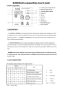
A BRIEF OVERVIEW
a – Auxiliary power supply indicator
b – Relay trip status indicator
c – Time delay status indicator
d – Down key
e – Up key
f – Reset key
g – Test key
h – DP indicator
i – FUNCTION indicator
j – VALUE indicator
1. DESCRIPTION
:
The ELR96 and ELR96A are microprocessor based numerical earth leakage relays designed to monitor
the leakage current in a electrical installation. With the use of microprocessor technology and digital signal
processing technique, the ELR96 and ELR96A relays are equiped with state-of-the-art digital hormonic
filter to minimise nuisance tripping.
The ELR96 & ELR96A relays can continuously display the leakage current on the front display panel.
When the relay trip as a result of a leakage being detected, the leakage current will be recorded. This reco-
ded leakage current and all the settings on the relay can be viewed at by pressing the RESET button on the
relay.
ELR96A comes with two additional remote control inputs.The additional inputs are remote test input and
the remote reset input. Other additional features of the ELR96 include positive safety output contact and 50%
pre-fault contact.
2. LIGHT INDICATORS
:
The indicators display the status of the system as follow:
Indicator
Status
0 0 0 0
1 0 1 ×
1 B 0 ×
1 0 ×
1 0 ×
0
×
B
NO auxiliary supply. 1 = NO
0 = OFF
Leakage current exceeded set limit,
X = Don’t care
time delay coundown started.
Delay time lapsed and relay tripped.
B = Blinking
VL = VALUE
FUNC = FUNCTION
Table 1:system status -1-
FUNC DP
OFF
VALUE
OFF Real-time leakage current.
1 Blink Sensitivity setting.
2 Blink Delay time setting.
Step 2:Press the UP and DOWN key simultaneously to enter
Programming mode. The function digit blinks to indic-
ates the relay is in programming mode.
Step 3:Use the UP or DOWN key to select the desired value.
3 Off Previous tripped leakage current. Step 4:TO save the selected value, press the UP and DOWN
Table 2:function codes key simultaneously. This will exit the programming
mode with the selected setting being saved.
Message Description
“E Ct” Error in ZCT connection TO exit programming mode without saving the selected setting,
Overflow . The measurement exceeded press the “RESET” key once.
the display range for the respective
sensitivity setting range.
“OFL”
Display range for sensitivity setting range
1:From 0.00A to 0.22A
Display range for sensitivity setting range
2:From 0.00A to 1.10A
4. REMOTE CONTROL INPUTS *
a) Remote test input
This digital input is similar to the “ TEST ” pushbutton.
To remotely test the relay, make a connection between
Display range for sensitivity setting range
3:From 0.00A to 3.10A
terminals 4 and 6 of the relay.
b) Remote reset input
“tESt ” Relay tripped under test mode This digital input is to remotely reset the relay when
Table 3:Display messages tripped. To reset the relay, make a connection between
terminals 4 and 5 of the relay.
3. PUSH-BUTTONS OPERATION
a) Trip test
Press the “TEST ” button to simulate a trip.
5. OUTPUT CONTACTS
a) Trip contact:
Condition.
b) Trip test
Press the “TSET” button to reset the relay
when tripped.
This is a latching type contact. It is activated under foll-
owing conditions:
- broken connection between the relay and the ZCT.
- leakage current exceeded the sensitivity setting.
c) View setting b) 50% pre-fault contact *
When the relay is not under tripped condition, pressing - Activated when leakage current reaches 50% of the
the “RESET” button will scroll through the various sensitivity setting.
functions of the relay.
OFF
FUNCTION 1 FUNCTION 2 FUNCTION 3
Figure 1:Scroll sequence
d) Program setting
Only function codes 1 and 2 can be programmed.
Setp 1:Press “RESET” key until the function digit
c) Safety contact *
- Activated when the auxiliary supply is connected and
the relay is functioning normally.
- De activated when connection to the ZCT from relay
is interrupted or auxiliary supply failure.
Shows required function.
-2-
6. TECHNICAL DATA
Models
ELR96-5 & ELR96A-5
ELR96-5 & ELR96A-6
Auxiliary Supply
Supply voltage
Rated frequency
VA rating
Setting
Sensitivity Adjustment
Delay Time Adjustment
Remote test /Reset inputs
Output
Trip Contact:
Rated voltage
Continuous carry
Make and carry for 0.2s
Safety Contact:*
Rated voltage
Continuous carry
Make and carry for 0.2s
50% Pre-fault Contact *
Rated voltage
Continuous carry
Make and carry for 0.2s
Contact specification:
Contact arrangement
Contact material
Operating time
Expected electrical life
Expected mechanical life
Approval
Indicators
Auxiliary supply
Time delay
Trip
Real-time leakage current
:50Hz
:60hz
:198~265 VAC
:OR 50Hz
:3 VA typical
:Range 1 is stepping from 0.03A 0.05 0.10A 0.15A
:Range 2 is from 0.20A to 0.75A in step of 0.05A
:Range 3 is from 0.80A to3.00A in step of 0.05A
:From 0.05 to 3.00 sec in step of 0.05 sec
:From 3.00 to 10.0 sec in step of 5.0 sec
:N.O.dry contact *
:250 VAC
:6A (COSψ=1.0)
:30A
:250 VAC
:5A (COSψ=1.0)
:10A
:250 VAC
:5A (COSψ=1.0)
:10A
:change-over
:Silver alloy
:15ms max.
:100,000 operations at rated current
:5 million operations
:UL / CSA,VDE,TUV
:green color LED indicator
:red color LED indicator
:7-segment LED and red color LED indicator
:7-segment LED
-3-
Mechanical
Mounting method
Front panel
Approximate weight
* Applicable to ELR96A series only
7. CONNECTION DIAGRAMS
8. CASE DIMENSIONS
:Panel mounting
:Standard DIN 96mm × 96mm
:0.8 kg
advertisement
* Your assessment is very important for improving the workof artificial intelligence, which forms the content of this project
Related manuals
advertisement