- Computers & electronics
- Telecom & navigation
- Mobile phones
- Car kits
- Cypress Semiconductor
- POWERPSOC CY3267
- Quick start Guide
advertisement

EVALUATION KIT QUICK START GUIDE
CY3267 POWERPS
O
C ® LIGHTING
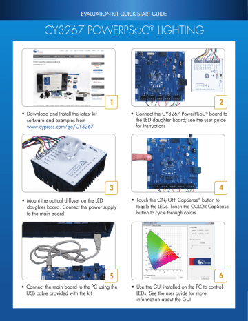
• Download and Install the latest kit
software and examples from
www.cypress.com/go/CY3267
1 2
• Connect the CY3267 PowerPSoC
for instructions
® board to
the LED daughter board; see the user guide
3
• Mount the optical diffuser on the LED
daughter board. Connect the power supply
to the main board
4
• Touch the ON/OFF CapSense ® button to
toggle the LEDs. Touch the COLOR CapSense
button to cycle through colors
5
• Connect the main board to the PC using the
USB cable provided with the kit
6
• Use the GUI installed on the PC to control
LEDs. See the user guide for more
information about the GUI
EVALUATION KIT QUICK START GUIDE
CY3267 POWERPS
O
C ® LIGHTING
CY3267 PowerPSoC Lighting Evaluation Kit Details
Power Supply Input
Debug Interface
Port Extension Header
Fan and Thermistor
Interface
VDD Selection Jumper
FirstTouch RF Interface
CY8CLED04DOCD1
PowerPSoC Device
Artaflex Radio
Module Interface
CapSense Buttons
Full Speed USB Interface
LED Daughter Board
Interface
Programming Header for
CY8CLED04DOCD1
Programming Header for CY8C24894
Main Board
Interface
Temperature
Sensor
HBLED
Module
CHANNEL
RED
(J6)
BLUE
(J7)
AMBER
(J10)
GREEN
(J11)
BUCK or BOOST TOPOLOGY
J6
BCK-BST
+ LED_RED+ (WHITE)
BCK or BST LED_RED- (ORANGE)
J7
BCK-BST
BCK or BST
+ LED_BLUE+ (PINK)
LED_BLUE- (BLUE)
BCK or BST
J10
BCK-BST
BCK or BST
BCK-BST
J11
+
+
LED_AMBER- (GRAY)
LED_AMBER+ (YELLOW)
BUCK - BOOST TOPOLOGY
J6
BCK-BST LED_RED- (ORANGE)
+ LED_RED+ (WHITE)
BCK or BST
J7
BCK-BST
+
LED_BLUE- (BLUE)
LED_BLUE+ (PINK)
BCK or BST
J10
BCK or BST
BCK-BST
+ LED_AMBER+ (YELLOW)
LED_AMBER- (GRAY)
LED_GREEN- (PURPLE)
LED_GREEN+ (BROWN)
BCK or BST
BCK-BST
J11
+ LED_GREEN+ (BROWN)
LED_GREEN- (PURPLE)
Refer to this image to connect the LED Daughter Card Interface on the main board and the Main Board Interface on the daughter board.
Note that the Buck or Boost Topology is required for the onboard firmware to work properly
For the latest information about this kit, visit www.cypress.com/go/CY3267
© 2011 - 2014 Cypress Semiconductor Corporation. All rights reserved.
All trademarks or registered trademarks referenced herein are the properties of their respective owners.
Doc.# 001-50556 Rev.*F
advertisement
* Your assessment is very important for improving the workof artificial intelligence, which forms the content of this project