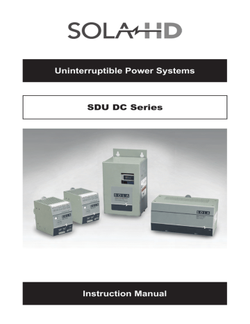
Installation Instructions. Emerson SDU 10-24, SDU DC DIN Rail UPS, SDU DC Series, SDU 20-24
Add to my manuals
28 Pages
advertisement

7.0 Installation Instructions
7.1 Placement
Install the power module and battery module in a protected area with adequate airflow and free of excessive dust. Do not operate the UPS outdoors.
7.2 DIN Rail Mounting
1. Tilt the unit as illustrated above.
2. Put the unit onto the DIN rail.
3. Push the unit downward until it stops.
4. Push at the lower front edge to lock. Gently shake the unit to ensure that the retainer has locked.
7.2.1 Removing the Unit from the DIN Rail
1. Push the button and swing the bottom up and out.
7.3 Chassis Mounting
Use the optional chassis mounting brackets (SDU-PMBRK). Please refer to the installation instructions supplied with the chassis mounting brackets.
NOTE: If you will be shipping the UPS already mounted, we recommend using the chassis mounting brackets (SDU-PMBRK) to secure the UPS.
SDU DC Series Instruction Manual • 8
7.4 SDU DC UPS with SDU 24-BAT Wiring Diagram
1
AC Source
24Vdc / 10A
22.5-28.5 Vdc
S O L A
100-240V~3.5A 50/60 Hz
+
-
DC Load
1 AC/DC Power Supply
2 Power Module: SDU 10-24 or SDU 20-24
3 Battery Module: SDU 24-BAT
OUTPUT DC
ON/OFF
Industrial DC UPS
ON/OFF/TEST
BATTERY FAULT
SDU 10-24
INPUT POWER OK
24Vdc/10A
INPUT
24Vdc/10A
LOAD
R
SDU 24-DB9
2 3
RS232-DB9
S O L A
SDU 24-BAT
Industrial DC UPS
Battery Module
BAT 1 BAT 2
3
Battery Polarized Cable Assembly
S O L A
SDU 24-BAT
Industrial DC UPS
Battery Module
BAT 1 BAT 2 BAT 2
Up to 4 SDU 24-BAT modules can be connected in parallel with the power modules SDU 10-24 or SDU 20-24
SDU DC Series Instruction Manual • 9
7.5 SDU DC UPS with SDU 24-BATEM Wiring Diagram
See Connection Diagram on Page 23
1
SDU 24-DB9
2
DB9
3
AC Source
24Vdc / 10A
22.5-28.5 Vdc
S O L A
Power Supply
SDN 10-24-100C
IND.CONT.EQ.
9HA0
100-240V~3.5A 50/60 Hz
Industrial DC UPS
ON/OFF/TEST
BATTERY FAULT
BATTERY MODE/
BATTERY CHARGE
INPUT POWER OK
SDU 10-24
24Vdc/10A
INPUT
24Vdc/10A
LOAD
R
IND.CONT.EQ.
3MCG
+
-
DC Load
S O L
SDU 24-BATEM
Industrial DC UPS
External Battery Module
A
Battery Polarized
Cable Assembly
BAT 1
1
AC/DC Power Supply
2 Power Module: SDU 10-24 or SDU 20-24
3 Battery Module: SDU 24-BATEM
Only 1 SDU 24-BATEM module can be connected in parallel with the power modules SDU 10-24 or SDU 20-24
7.6 Connections
1. Use the polarized cable to connect the power module to the battery module.
2. Connect the power module dc input connector to the 24 V dc input power source.
3. Hardwire the load to the power module output terminal connector.
7.7 Charge the Battery
The UPS charges the battery whenever it is connected to 24 V dc input power.
For best results, charge the battery for 4 hours during initial use.
SDU DC Series Instruction Manual • 10
7.8 Turn “ON” the UPS (Normal Mode)
To start the UPS, press and hold the ON/OFF/TEST button until a short “beep” is heard. (This should take less than 3 seconds.) Immediately release the ON/OFF/
TEST button; the UPS is now “ON” and the green LED is continuously lit.
Depressing the ON/OFF/TEST button for 5 seconds will turn the UPS OFF.
7.9 Turn “ON” the UPS (Green Mode)
With the UPS OFF, depress the ON/OFF/TEST button until 2 short “beeps” are heard. (This should take about 4 seconds.) Release the ON/OFF/TEST button; the UPS is now “ON” with the Green Mode enabled. The green LED will now double flash for a period of 5 seconds and then remain solid green for 55 seconds. This pattern will be repeated every minute.
To deactivate the Green Mode, the UPS must be turned OFF using the ON/OFF/
TEST button and restarted using the Normal Mode sequence (See 7.8).
7.9.1 About the Green Mode
The Green Mode is an energy saving feature that prevents the UPS battery from being deeply discharged in the case of an extended power outage.
If during a power outage the UPS detects a battery load power of less than 15 watts, the UPS will shut down after 3 minutes of low power operation. The UPS will then beep every 30 seconds indicating that it is now in the power saving mode. When power is restored to the system, the UPS will automatically restart in the Green Mode.
Note that if the power outage lasts longer than 72 hours the UPS will completely turn OFF and will have to be manually restarted in the selected “ON” Mode using the ON/OFF/TEST button.
7.10 Remote ON/OFF
To activate the Remote ON/OFF function, connect a remote push-button switch to the ON/OFF terminal as shown below.
The Remote ON/OFF switch provides the same functions as the front panel switch, including the ON/OFF/TEST functions with the Green Mode enabled or disabled. If the Green Mode is not needed, a remote toggle switch can be used.
Remote push-button switch
OUTPUT DC
24V/35mA
REMOTE
ON/OFF
SDU DC Series Instruction Manual • 11
advertisement
* Your assessment is very important for improving the workof artificial intelligence, which forms the content of this project
Related manuals
advertisement
Table of contents
- 1 SDU DC Series
- 3 Table of Contents
- 4 Important Safety Instructions
- 5 Warnings Defined
- 6 Introduction
- 7 What’s Included
- 7 Battery Options
- 7 Optional Accessories
- 8 Installation Instructions
- 12 Operating Instructions
- 14 Alarms
- 15 Replacing the Battery
- 23 Battery Backup Times
- 24 Power Module Specifications
- 25 Battery Module Specifications
- 26 Troubleshooting
- 27 Storage
- 27 Product Registration & Warranty