Repairs. Mini COOPER S, 2003 Cooper, 2003 Hardtop 2-door, Cooper, Cooper 2003, 2003 HARDTOP 2 DOOR, Cooper S 2003, 2003
Add to My manuals148 Pages
advertisement

ba.book Seite 105 Montag, 5. August 2002 8:09 20
Repairs
OVERVIEW
CONTROLS
OPERATION, CARE, MAINTENANCE
OWNER SERVICE PROCEDURES
TECHNICAL DATA
INDEX
105
Online Edition for Part-No. 01 41 0 156 890 - © 09/02 BMW AG
ba.book Seite 106 Montag, 5. August 2002 8:09 20
ON-BOARD TOOL KIT WINDSHIELD WIPER BLADES
106
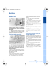
Storage location
The picture shows as an example tire change set with on-board tools for vehicles with the space-saver spare tire.
Depending on the level of equipment options, your MINI is fitted with a special on-board tool kit stored at the following locations:
Tire change set for space-saver spare tire:
In the cargo area under the floor mat.
MINI Mobility System with tire change set and on-board tools:
In the cargo area under the floor mat.
Tire change set and on-board tools for Run
Flat tires:
Tire change set: in cargo area in a separate bag – On-board tools: on the left behind the side panels next to the emergency kit,
Windshield wiper
1. Rotate the wiper arm completely out from the windshield
2. Set the wiper blade at an angle
3. Press the securing spring, see arrow
4. Unhook the wiper blade towards the windshield
5. Pull the wiper blade past the wiper arm toward the top
6. Insert the new wiper blade
7. Press into position until you hear it engage.
Rear window wiper
1. Rotate the wiper arm completely out from the windshield
2. Turn the wiper blade as far as it will go to the rear, see arrow
3. Press the wiper blade against the limit and thus out of the mounting
4. Press the new wiper blade into the mounting.
Online Edition for Part-No. 01 41 0 156 890 - © 09/02 BMW AG
ba.book Seite 107 Montag, 5. August 2002 8:09 20
LAMPS AND BULBS
Proceed carefully when handling lamps and bulbs. If you are not familiar with any of the procedures, consult your MINI Dealer.
Do not touch the glass portion of a new bulb with your bare hands since even small amounts of impurities burn into the surface and reduce the service life of the bulb. Use a clean cloth, paper napkin, or similar material, or hold the bulb by its metallic base.
<
1. Pull on the tab of the cover of the defective lamp and open it
2. Press the retaining wire lightly at the eyelet and at the same time guide it outwards
3. Fold the retaining wire down
4. Remove the lamp holder and replace the lamp
5. Reinsert the lamp holder in the correct position
6. Fold the retaining wire back up and catch in place. Ensure that it is placed in the middle of the wire connector.
Replacement bulbs are available from your
MINI Dealer.
1 Low beams
H7 bulb, 55 Watts
Whenever working on the electrical system, switch off the electrical accessory you are working on or disconnect the cable from the negative terminal of the battery. Failure to do this could result in short circuits.
To prevent injuries and damage, comply with any instructions provided by the bulb manufacturer.
<
2 High beams
H7 bulb, 55 Watts
The H7 bulb is pressurized. Therefore, wear safety glasses and protective gloves. If the lamp is damaged there is a risk of injury.
<
Replacing bulbs
The headlamps are integrated into the
MINI engine bonnet.
Xenon lamps*
The service life of these bulbs is very long and the probability of a failure is very low, provided that they are not switched on and off an unusual number of times. If one of these bulbs should nevertheless fail, it is possible to continue driving with great caution using the fog lamps, provided traffic laws in your area do not prohibit this.
Because of the extremely high voltages involved, any work on the xenon lighting system should be carried out by technically-qualified personnel only. Otherwise, there is a risk of fatal injury.
<
107
Online Edition for Part-No. 01 41 0 156 890 - © 09/02 BMW AG
ba.book Seite 108 Montag, 5. August 2002 8:09 20
LAMPS AND BULBS
108
Turn signal indicators, front
21 Watt bulb
1. Open the bonnet
2. Reach into the opening for the turn signal indicators from above
3. Apply gentle pressure to the bulb holder while turning it to the left
4. Remove and replace the bulb.
Side turn signal indicators
5 Watt bulb
1. Press the bulb towards the rear of the vehicle and remove
2. Remove and replace the bulb.
Parking lamps and standing lamps
5 Watt bulb
The parking lamps and standing lamps are integrated in the lamp housing of the turn signal indicator.
1. Turn the bulb holder to the left and pull out
2. Remove and replace the bulb.
Side marker lamps
3 Watt bulb
Side marker lamps in the wheelhouse paneling of the bumper.
Please contact a MINI Dealer in case of a malfunction.
Fog lamps*
H11 bulb, 55 Watts
Please contact a MINI Dealer in case of a malfunction.
Online Edition for Part-No. 01 41 0 156 890 - © 09/02 BMW AG
ba.book Seite 109 Montag, 5. August 2002 8:09 20
LAMPS AND BULBS
Tail lamps
Rear lamp – 3: bulb 21/5 Watts
Other bulbs: 21 Watts
1 Rear fog lamp – not active
2 Turn signal indicator
3 Rear lamp
4 Rear lamp/Brake lamp red yellow red red
To make this clear, the illustration shows a dismantled tail lamp with the bulb holder removed. All of the bulbs are integrated in the bulb holder.
To reach the bulb holder, remove the cover of the side trim panel in the cargo area.
Backup lamp
MINI COOPER:
Access to the lamp via the back or underside of the bumper.
1. Press the clips together
2. Push the lamp out of the bumper
3. Apply gentle pressure to the bulb while turning it to the left
4. Remove and replace the bulb.
Replacing bulbs
1. Unplug the power supply
2. Release the bulb holder, see arrow, and remove
3. Apply gentle pressure to the bulb while turning it to the left
4. Remove and replace the bulb
5. Plug in the power supply receptacle
6. Press the bulb holder into position until you hear it engage.
MINI COOPER S:
Please contact a MINI Dealer in case of a malfunction.
109
Online Edition for Part-No. 01 41 0 156 890 - © 09/02 BMW AG
ba.book Seite 110 Montag, 5. August 2002 8:09 20
LAMPS AND BULBS
110
Center high-mount brake lamp
LED strip on the tailgate.
Please contact a MINI Dealer in case of a malfunction.
License plate lamps
5 Watt bulb
1. Apply a screwdriver to the recess and lever out the lamp cover
2. Replace the bulb.
Interior lamps
6 Watt xenon bulb
1. Press out the lamp cover with a screwdriver
2. Remove and replace the bulb.
Reading lamps
2 x 6 Watt xenon bulbs
1. Press out the lamp cover with a screwdriver
2. Unscrew the entire lamp with a screwdriver
3. Remove the bulb from above and replace.
Online Edition for Part-No. 01 41 0 156 890 - © 09/02 BMW AG
ba.book Seite 111 Montag, 5. August 2002 8:09 20
LAMPS AND BULBS
Footwell lamps
5 Watt bulb
1. Press out the lamp cover with a screwdriver
2. Remove and replace the bulb.
Illuminated vanity mirror
Lamps in the vanity mirror in the sun visor.
Please contact a MINI Dealer in case of a malfunction.
Cargo area lamps
5 Watt bulb
1. Press the lamp cover to the left and out with a screwdriver.
2. Remove and replace the bulb.
Glove compartment lamp
5 Watt bulb
1. Press out the lamp cover with a screwdriver
2. Remove and replace the bulb.
111
Online Edition for Part-No. 01 41 0 156 890 - © 09/02 BMW AG
112
ba.book Seite 112 Montag, 5. August 2002 8:09 20
REPAIRING A FLAT TIRE CHANGING TIRES – MINI WITH SPACE-SAVER SPARE TIRE
*
Safety measures in the event of a flat tire:
Stop the vehicle as far as possible from passing traffic. Switch on the hazard warning flashers.
Turn the steering wheel to the straightahead wheel position and engage the steering lock. Engage the parking brake and shift into 1st or reverse gear – selector lever in P.
All passengers should be outside the vehicle and well away from your immediate working area – behind a guardrail, for instance.
If a warning triangle or portable hazard warning lamp is available, set it up on the roadside at an appropriate distance from the rear of the vehicle. Comply with all safety guidelines and regulations.
<
Additional safety measures in the event of a wheel change:
Change the wheel only on a level, firm surface which is not slippery.
Avoid jacking the vehicle on a soft or slippery support surface – on snow, ice, loose gravel, etc. – as either the vehicle or the jack could slip sideways.
Do not use a wooden block or similar object as a support base for the jack, as this would prevent it from extending to its full support height and reduce its load-carrying capacity.
Do not lie under the vehicle or start the engine when the vehicle is supported by the jack – risk of fatal injury.
<
In the event of a flat tire, different procedures should be followed depending on the equipment included in your MINI:
>Vehicles with space-saver spare tire, see the next chapter
>Vehicles with Run Flat tires, see page 116
>Vehicles with MINI Mobility System, see
.
To change a space-saver tire, proceed as follows:
>Remove the space-saver spare tire, see
>Prepare the vehicle, see page 114
>Jack up the vehicle, see page
>Fit the space-saver spare tire, see
>Tighten the lug bolts, see page 115
>Drive with space-saver spare tire, see
.
Tire change set
On vehicles with a space-saver spare tire, the tire change set is stored in the cargo area under the floor mat.
1 Chock, folding
2 Hubcap remover
3 Wheel stud wrench
4 Jack
5 Spanner
6 Tow fitting
7 Lifting handle
Online Edition for Part-No. 01 41 0 156 890 - © 09/02 BMW AG
ba.book Seite 113 Montag, 5. August 2002 8:09 20
CHANGING TIRES – MINI WITH SPACE-SAVER SPARE TIRE
*
Removing the space-saver spare tire
The screw connection of the space-saver spare tire is in the cargo area under the floor mat, on the base of the storage compartment for the tire change set.
1. Loosen the screw connection using the wheel lug bolt wrench
2. Take out the cover panel
3. Screw the lifting handle from the onboard tool kit onto the thread
4. Raise the lifting handle slightly
5. Squeeze the securing springs
6. The space-saver spare tire is released and must be held by the lifting handle
7. Lower the space-saver spare tire with the lifting handle
8. Unscrew the lifting handle again
113
Online Edition for Part-No. 01 41 0 156 890 - © 09/02 BMW AG
114
ba.book Seite 114 Montag, 5. August 2002 8:09 20
CHANGING TIRES – MINI WITH SPACE-SAVER SPARE TIRE
*
9. Pull out the space-saver spare tire towards the rear underneath the vehicle
10. Position the space-saver spare tire with the valve facing upwards
11. Unscrew the valve extension from the valve of the space-saver spare tire
12. Unscrew the dust cap from the extension and attach to the space-saver spare tire.
Preparing the vehicle
Read and comply with the safety pre-
cautions provided on page 112 .
<
1. Secure the vehicle to prevent it from rolling:
Place the folding chock behind the front wheel on the other side of the vehicle; on downward inclines, place it in front of this wheel.
If the wheel is changed on a surface with a more severe slope, take additional precautions to secure the vehicle from rolling
2. Loosen the lug bolts by a half turn.
Jacking up the vehicle
1. Place the jack at the jacking point closest to the wheel.
The jack base must be perpendicular to the surface beneath the jacking point
Online Edition for Part-No. 01 41 0 156 890 - © 09/02 BMW AG
ba.book Seite 115 Montag, 5. August 2002 8:09 20
CHANGING TIRES – MINI WITH SPACE-SAVER SPARE TIRE
*
2. Insert the jack head for jacking up in the square recess of the jacking point
3. Jack the vehicle up until the wheel you are changing is raised from the ground.
Fitting the space-saver spare tire
The vehicle jack is designed for changing wheels only. Do not attempt to raise another vehicle model with it or to raise any load of any kind. To do so could cause accidents and personal injury.
<
1. Unscrew the lug bolts and remove the wheel
2. Remove accumulations of mud or dirt from the mounting surfaces of the wheel and hub. Clean the lug bolts
3. Fit the space-saver spare tire
4. Screw at least two lug bolts finger-tight into opposite bolt holes
5. Screw in the remaining bolts
6. Tighten all the lug bolts firmly in a diagonal pattern
7. Lower the vehicle
8. Remove the jack.
Tightening the lug bolts
Tighten the lug bolts in a diagonal pattern.
As soon as possible, have the secure seating of the lug bolts – tightening torque 88.5 lb ft / 120 Nm – checked using a calibrated torque wrench. Otherwise, a wheel coming loose can lead to a severe accident.
<
Driving with the space-saver spare tire
Drive cautiously. Do not exceed a speed of
50 mph / 80 km/h.
You must expect changes in vehicle handling such as delayed braking response, longer braking distances, and changes in self-steering properties when close to the handling limits.
Only one space-saver spare tire may be mounted at one time. Reinstall wheels and tires of the same size and specification as soon as possible. Maintain pre-
scribed tire pressures, see page 85 .
<
Do not try to fit a full hubcap to the spacesaver spare tire, as the hubcap could be damaged.
Check and correct the tire inflation nity.
< pressure at the earliest opportu-
Replace the defective tire as soon as possible and have the new wheel/tire assembly balanced.
115
Online Edition for Part-No. 01 41 0 156 890 - © 09/02 BMW AG
116
ba.book Seite 116 Montag, 5. August 2002 8:09 20
FLAT TIRE– RUN FLAT TIRES
*
You will recognize Run Flat tires by a circular symbol containing the letters RSC on the side of the tire.
Run Flat tires consist of self-contained tires and special rims. The tire reinforcement ensures that the tire retains some residual safety in the event of pressure drop and driving remains possible to a restricted degree.
Flat tire
The yellow indicator lamp in the instrument cluster lights up to indicate a flat tire.
In addition, a gong sounds, see pages 17 ,
1. Reduce vehicle speed carefully to under
50 mph / 80 km/h, avoiding hard brake applications and steering maneuvers.
2. Do not exceed a speed of 50 mph /
80 km/h.
3. Identify damaged tires; check tire inflation pressures on all four wheels at the
4. Correct the tire inflation pressure if you wish to continue your journey and this is permitted, see next text section
5. Have damaged tires changed by your
.
Your MINI Dealer has the information needed for working with Run Flat tires and is equipped with the necessary special tools. They provide advice if you wish to replace the tires on your MINI, or reequip from summer to winter tires or vice
.
<
For safety reasons, do not have a damaged safety tire repaired.
<
The reinforcement on the flanks of the Run Flat tires means that it is usually not possible to detect an air loss from outside.
<
Online Edition for Part-No. 01 41 0 156 890 - © 09/02 BMW AG
ba.book Seite 117 Montag, 5. August 2002 8:09 20
FLAT TIRE – RUN FLAT TIRES
*
Continuing driving with a damaged tire
With Run Flat tires, you can continue driving under certain conditions, depending on the vehicle load and the severity of the tire damage, at a maximum speed of 50 mph /
80 km/h.
You can determine the possible mileage for continued driving on the basis of the following general indications:
>Tire inflation pressure 0 psi / 0 kPa: approx. 95 miles / 150 km
>Tire inflation pressure 7.2–14.5 psi /
50–100 kPa: approx. 300 miles / 500 km
>Tire inflation pressure greater than
14.5 psi / 100 kPa: approx. 600 miles / 1,000 km.
Tire change set
Your MINI is additionally equipped with a tire change set. This is located in the MINI
COOPER in the cargo area under the floor mat.
In the MINI COOPER S the tire change set is located in a separate bag which is attached to the eyelets on the cargo area floor by
means of tie-down straps, see page 75 .
When changing a tire, always observe the
safety measures on page 112 , and follow
the procedure described on page 114
ff.
In case of a flat tire the tire change set is not needed, since your MINI has
Run Flat tires.
<
117
Online Edition for Part-No. 01 41 0 156 890 - © 09/02 BMW AG
118
ba.book Seite 118 Montag, 5. August 2002 8:09 20
FLAT TIRE – MINI MOBILITY SYSTEM
*
MINI Mobility System
To repair a flat tire you will find a MINI
Mobility System in your MINI. With the help of this system you can apply a liquid sealant on the inside of the tire, which seals the damaged area and enables you to continue to drive.
Using the MINI Mobility System
In order to repair a flat tire with the MINI
Mobility System, proceed as follows:
>Prepare for tire repair, see page 119
>Pump in liquid sealant, see page
>Reinflate the tire, see page 120
>Distribute liquid sealant, see page
>Check tire inflation pressure, see
MINI Mobility System with on-board tools
The MINI Mobility System with tire change set and on-board tools is located in the cargo area under the floor mat:
1 Jack
2 Chock, folding
3 Wheel stud wrench
4 Hubcap remover
5 Lug wrench, Phillips screwdriver, towing eyelet
6 Compressor, hose with manometer and plug for cigarette lighter socket
7 Package with filling hose, valve remover, valve core and spare valve
8 Filling canister
9 Hex wrench/screwdriver
10 Adapter for wheel lug lock
Online Edition for Part-No. 01 41 0 156 890 - © 09/02 BMW AG
ba.book Seite 119 Montag, 5. August 2002 8:09 20
FLAT TIRE – MINI MOBILITY SYSTEM
*
Preparing for tire repair
Before using the MINI Mobility System read the warning and danger precautions on the equipment.
<
If possible, leave objects in which have been forced into the tire.
Take off the tag regarding speed limits and stick it onto the steering wheel.
5. Remove the cap from the filling hose
6. Push the filling hose onto the tire valve
7. Hold the filling canister with the cap down and squeeze.
Squeeze the entire contents of the canister into the tire
8. Remove filling hose
9. Screw valve core into the tire valve with the valve remover.
Please remember that the liquid canister must be replaced every four years by your MINI Dealer if the equipment has not been used.
<
The instructions for using the MINI
Mobility System are also given on the equipment.
<
Pumping in liquid sealant
1. Shake the filling canister
2. Screw the filling hose onto the filling canister
3. Unscrew the dust protection cap from the valve of the defective tire
4. Screw out the valve core with the valve remover. The valve remover is located in a package with the filling hose
Place the valve core and valve remover only on clean surfaces.
<
In the event of a dirty valve core or of losing it you will find another valve core in a package with the filling hose.
<
119
Online Edition for Part-No. 01 41 0 156 890 - © 09/02 BMW AG
120
ba.book Seite 120 Montag, 5. August 2002 8:09 20
FLAT TIRE – MINI MOBILITY SYSTEM
*
Reinflating the tire
1. Screw hose 1 with manometer onto the tire valve
2. Connect plug 3 to the cigarette lighter socket in the vehicle interior, see
3. Ignition key in position 1:
Turn on compressor 2
4. Pump up the tires to at least 26.1 psi /
180 kPa, but not to more than 36.2 psi /
250 kPa.
To check the current air pressure, shut off the device for a short time
Do not run the compressor for longer than 6 minutes, otherwise the device will overheat and possibly be damaged.
<
If an air pressure of 26.1 psi /
180 kPa cannot be reached, drive back and forth about 35 ft / 10 m so that the liquid sealant is distributed in the tire. Afterwards repeat the procedure.
If an air pressure of 26.1 psi / 180 kPa is still not reached, the tire is too badly damaged. Please contact the nearest
MINI Dealer.
<
5. Turn off compressor 2
6. Unscrew hose 1 from the tire valve
7. Store the MINI Mobility System back in the vehicle.
Distributing liquid sealant
Immediately drive for 10 minutes, so that the liquid sealant is uniformly distributed.
Do not exceed a speed of 40 mph /
60 km/h).
If possible do not drive at a speed lower than 10 mph / 20 km/h. Stop at a suitable location.
<
Online Edition for Part-No. 01 41 0 156 890 - © 09/02 BMW AG
ba.book Seite 121 Montag, 5. August 2002 8:09 20
FLAT TIRE – MINI MOBILITY SYSTEM
*
Checking tire inflation pressure
1. After driving for 10 minutes:
Screw hose with manometer back onto the tire valve
2. Check tire pressure
The tire inflation pressure must be at least 18.8 psi / 130 kPa.
If it is not, do not continue driving.
<
If 18.8 psi / 130 kPa are displayed:
3. Ignition key position 1:
Turn on compressor 2. Correct tire inflation pressure to the prescribed value, see
tire inflation pressure table, page 86
4. Replace the tire as soon as possible.
Driving on
Do not exceed the permitted maximum speed of 50 mph / 80 km/h, otherwise an accident could happen.
<
Replace the defective tire as soon as possible and have the new wheel/tire assembly balanced.
Have the MINI Mobility System refilled.
Please contact your MINI Dealer. They provide advice if you wish to replace the tires on your MINI or re-equip from summer to winter tires or vice versa.
<
Tire change set
Your MINI is additionally equipped with a tire change set. This is located in the MINI
COOPER in the cargo area under the floor mat.
When changing a tire, always observe the
safety measures on page 112 , and follow
the procedure described on page 114
ff.
In case of a flat tire the tire change set is not necessary due to the availability of the MINI Mobility System.
<
The use of the MINI Mobility System may be ineffective with tire damage larger than approx.
3
/
16
in / 4 mm. Please contact the nearest MINI Dealer if the tire cannot be made drivable with the MINI
Mobility System.
<
121
Online Edition for Part-No. 01 41 0 156 890 - © 09/02 BMW AG
122
ba.book Seite 122 Montag, 5. August 2002 8:09 20
BATTERY
Location in the MINI COOPER
The battery is located in the engine compartment.
.
Location in the MINI COOPER S
The battery is located in the cargo area under the floor mat.
Battery care
The battery is absolutely maintenance-free, that is, the original electrolyte will normally last for the service life of the battery under moderate climatic conditions.
Charging the battery
Only charge the battery in the vehicle via the terminals in the engine compartment with the engine switched off, see "Jumpstarting" on page
.
For all questions regarding the battery, please consult your MINI
Dealer.
<
Whenever working on the electrical system, disconnect the cable from the negative terminal of the battery. Failure to do this could result in fire hazards or injury due to short circuits.
<
Disposal
Return used batteries to a recycling point or your MINI Dealer. Maintain the battery in an upright position for transport and storage. Secure the battery to prevent it from tilting during transport.
<
Online Edition for Part-No. 01 41 0 156 890 - © 09/02 BMW AG
ba.book Seite 123 Montag, 5. August 2002 8:09 20
FUSES
If an electrical device fails, switch it off and check the fuse.
Plastic tweezers that you can use to pull fuses out of their sockets can be found in the fuse box in the vehicle interior, see next column.
In the vehicle interior
On the left side of the footwell in the side trim panel.
Open the cover panel of the fuse box. To do so, press the fastener.
In the engine compartment
In the MINI COOPER on the right next to the battery.
In the MINI COOPER S on the right next to the air filter box.
Open the cover panel of the fuse box. To do so, press the clip fastener.
Do not attempt to repair a blown fuse or replace it with a fuse of a different color or Ampere rating. To do this could cause a fire in the vehicle resulting from a circuit overload.
<
If a fuse blows a second time, have the cause of the damage rectified by your MINI Dealer.
<
123
Online Edition for Part-No. 01 41 0 156 890 - © 09/02 BMW AG
124
ba.book Seite 124 Montag, 5. August 2002 8:09 20
WARNING TRIANGLE
*
FIRST-AID KIT
*
JUMP-STARTING
Do not use spray starter fluids to start the engine.
<
When your battery is discharged, you can use two jumper cables to start your vehicle with power from the battery in a second vehicle. Correspondingly you can help start another vehicle. Only use jumper cables with fully insulated handles on the terminal clamps.
The warning triangle is located beneath the luggage compartment cover.
The first-aid kit is located on the left in the luggage compartment, behind the side trim panel.
Comply with legal requirements requiring you to carry a hazard warning triangle in the vehicle.
<
Some articles in the first-aid kit are perishable. For this reason, check the expiration dates of each of the items regularly, and replace any whose expiration dates have passed. Source: any pharmacy.
Comply with legislation requiring you to carry a first-aid kit in the vehicle.
<
Do not touch live wiring and cables on a running engine. There is a risk of fatal injury if you do this. Carefully observe the following instructions to avoid personal injury and/or damage to either vehicle or both vehicles.
<
Online Edition for Part-No. 01 41 0 156 890 - © 09/02 BMW AG
ba.book Seite 125 Montag, 5. August 2002 8:09 20
JUMP-STARTING
Preparing for jump-starting
1. Check whether the battery of the support vehicle has 12 Volts and approximately the same capacity – measured in
Ah, printed on the battery
2. Switch off the engine of the support vehicle
3. Switch off any electrical systems and components in both vehicles – except for the hazard warning flashers of the support vehicle.
>Do not disconnect the discharged battery from the vehicle electrical system
>Make certain that there is no contact between the bodywork of the two vehicles – short circuit hazard!
4. With the battery of the MINI COOPER, remove the cover panel. To do so, press both clips at the same time or with the MINI COOPER S, open the cover of the positive terminal connection for jump-starting
*
, see arrow 1.
Connect the jumper cables
Adhere to the sequence also when providing support for other vehicles; failure to observe this procedure can lead to sparks at the terminals and pose an injury hazard.
<
Performing the jump-start
1. Start the engine of the vehicle providing the current and allow to run at a fast idle speed for several minutes
2. Start the engine on the vehicle with the discharged battery in the usual manner.
>If the first start attempt is not successful, wait a few minutes before another attempt in order to allow the discharged battery to recharge
1. On the MINI COOPER S, the positive terminal connection for jump-starting, see arrow 1, functions as the positive battery terminal.
Make a connection with the "+" jumper cable between the positive terminal of the discharged battery and the positive terminal of the support battery
2. Use the second, "–" jumper cable to set up the connection between the negative terminals of both vehicles.
To do so:
>Connect one terminal clamp to the negative terminal and/or to an engine or body ground of the support vehicle
>Connect the second terminal clamp to the negative terminal of the battery and/or to an engine or body ground of the vehicle to be started. For the MINI, see arrow 2.
On the MINI:
Before disconnecting the jumper cables, switch on the lighting, rear window defroster and the highest blower speed as well as the engine for at least approx.
10 seconds to prevent a voltage surge from the regulator to the electrical systems and components.
<
3. Then disconnect the jumper cables in the reverse order.
If necessary have the battery checked and completely charged at a MINI Dealer.
125
Online Edition for Part-No. 01 41 0 156 890 - © 09/02 BMW AG
126
ba.book Seite 126 Montag, 5. August 2002 8:09 20
TOWING
Avoid staggered towing and be careful that the towing rope is in tight tension before starting to drive the vehicle that is towing.
<
For towing, use either a tow bar or a nylon rope or nylon belts that prevent sudden jerking movements.
Tow fitting
The screw-in tow fitting is stored in the onboard tool kit; be sure that it remains in the vehicle at all times. This fitting is designed for installation in the tow sockets located at the front and rear of the vehicle.
It is intended for towing on paved road surfaces only.
Access to tow sockets
Use a suitable object – e.g. credit card, screwdriver – to press out the covers from the recess.
Firmly screw in the towing eyelet until it stops. If this is not done, the threads could be damaged.
Never attach tie-down hooks, chains, straps, or tow hooks to tie rods, control arms, or any other part of the vehicle suspension, as severe damage to these components will occur, possibly leading to accidents.
<
Tow bars
If the tow fittings of the two vehicles are not directly opposite one another, please note:
>Clearance and maneuvering capability will be strictly limited in corners
>The inclination of the tow bar generates lateral force – critical above all if the road surface is slippery.
Do not tow a vehicle that is heavier than the towing vehicle, otherwise it will no longer be possible to control the vehicle's response.
<
Online Edition for Part-No. 01 41 0 156 890 - © 09/02 BMW AG
ba.book Seite 127 Montag, 5. August 2002 8:09 20
TOWING
Tow-starting
It is not possible to start the engine of a vehicle equipped with an automatic transmission by towing or pushing.
For instructions on jump starting, refer to page
Never attempt to use your vehicle to push another car, since damage to the energyabsorbing bumpers could result.
Towing a vehicle
Only tow vehicles with Continuously
Variable automatic Transmission
(CVT) with the front wheels raised or on a special transport vehicle, otherwise the transmission can be damaged.
<
1. Place gear selector lever in neutral or idle
2. Towing speed:
Max. 45 mph / 70 km/h
3. Towing distance:
Max. 95 miles / 150 km
4. Leave the ignition key at position 1 to ensure that the brake lamps, turn signals, horn and windshield wipers remain operative, and to prevent the steering lock detent from engaging
5. Switch on the hazard-warning system, observe country-specific regulations.
Find some means of identifying the vehicle in tow, for instance, place a sign or warning triangle in the rear window.
Make sure that the ignition key remains in position 1 even when the electrical system has failed to prevent the steering lock from engaging.
The steering and brakes are without power assist when the engine is off. This means that increased effort is required for steering and braking.
<
Towing with a commercial tow truck
>Do not tow with sling-type equipment
>Use a wheel-lift or flatbed carrier
>Please comply with applicable towing laws.
Never allow passengers to ride in a towed vehicle for any reason.
<
127
Online Edition for Part-No. 01 41 0 156 890 - © 09/02 BMW AG
ba.book Seite 128 Montag, 5. August 2002 8:09 20
128
Online Edition for Part-No. 01 41 0 156 890 - © 09/02 BMW AG
advertisement
Related manuals
advertisement