advertisement
 Motherboard | Manualzz")
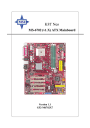
MS-6702 ATX Mainboard
Connectors
The mainboard provides connectors to connect to FDD, IDE HDD, case, modem, LAN, USB Ports, IR module and CPU/System/Power Supply FAN.
Floppy Disk Drive Connector: FDD1
The mainboard provides a standard floppy disk drive connector that supports 360K, 720K, 1.2M, 1.44M and 2.88M floppy disk types.
FDD1
IrDA Infrared Module Header: JIR1
The connector allows you to connect to IrDA Infrared module. You must configure the setting through the BIOS setup to use the IR function.
JIR1 is compliant with Intel
®
Front Panel I/O Connectivity Design Guide.
Pin
3
4
1
2
5
6
Signal
NC
NC
VCC5
GND
IRTX
IRRX
2
1
JIR1
6
5
Chassis Intrusion Switch Connector: JCASE1
This connector is connected to a 2-pin chassis switch. If the chassis is opened, the switch will be short. The system will record this status and show a warning message on the screen. To clear the warning, you must enter the BIOS utility and clear the record.
GND
CINTRU
2
1
JCASE1
2-18
Hardware Setup
Fan Power Connectors: CFAN1/SFAN1/PWFAN1/PWFAN2
The CFAN1 (processor fan), SFAN1 (system fan), PWFAN1 (Power
Supply fan) and PWFAN2 (Power Supply fan) support system cooling fan with +12V. It supports three-pin head connector. When connecting the wire to the connectors, always take note that the red wire is the positive and should be connected to the +12V, the black wire is Ground and should be connected to
GND. This mainboard has a System Hardware Monitor chipset on-board, so that you must use a specially designed fan with speed sensor to take advantage of the CPU fan control.
GND
+12V
SENSOR
CFAN1
GND
+12V
SENSOR
SFAN1
GND
+12V
SENSOR
PWFAN1
GND
+12V
SENSOR
PWFAN2
MSI Reminds You...
1. Always consult the vendors for proper CPU cooling fan.
2. CFAN1 supports the fan control.
You can install Core Center utility that will automatically control the CPU fan speed according to the actual CPU temperature.
Front USB Connectors: JUSB1 / JUSB2
The mainboard provides two USB 2.0 pin headers
JUSB1
&
JUSB2
that are compliant with Intel ® I/O Connectivity Design Guide. USB 2.0 technology increases data transfer rate up to a maximum throughput of 480Mbps, which is 40 times faster than USB 1.1, and is ideal for connecting high-speed USB interface peripherals such as
USB HDD
,
digital cameras
,
MP3 players
,
printers
,
modems and the like
.
2
1
JUSB1
10
9
2
1
JUSB2
10
9
Pin Definition
7
9
3
5
PIN SIGNAL
1 VCC
USB0-
USB0+
GND
Key
4
6
PIN SIGNAL
2 VCC
USB1-
USB1+
8
10
GND
USBOC
2-19
MS-6702 ATX Mainboard
Front Panel Connectors: JFP1 & JFP2
The mainboard provides two front panel connectors for electrical connection to the front panel switches and LEDs. JFP1 and JFP2 are compliant with Intel
®
Front Panel I/O Connectivity Design Guide.
Reset
Switch
HDD
LED
9
10
Power
Switch
Power
LED
JFP1
1
2
JFP2
7
8
Power
LED
1
2
Speaker
PIN
7
8
5
6
9
3
4
1
2
JFP1 Pin Definition
SIGNAL
HD_LED_P
FP PWR/SLP
HD_LED_N
FP PWR/SLP
RST_SW_N
PWR_SW_P
RST_SW_P
PWR_SW_N
RSVD_DNU
DESCRIPTION
Hard disk LED pull-up
MSG LED pull-up
Hard disk active LED
MSG LED pull-up
Reset Switch low reference pull-down to GND
Power Switch high reference pull-up
Reset Switch high reference pull-up
Power Switch low reference pull-down to GND
Reserved. Do not use.
JFP2 Pin Definition
PIN SIGNAL
1
3
5
7
GND
SLED
PLED
NC
PIN SIGNAL
2
4
6
8
SPK-
BUZ+
BUZ-
SPK+
MSI Reminds You...
If the Power LED on the front panel flashes every two seconds, this signal tells you that one of the power connection has been protected; if the Power LED flashes every one second, it tells that the CUP has been protected due to overheating. To refresh the system, please disconnect the power cable from the computer, and then reconnect the power cable to the computer again in at least five senconds.
CD-In Connector: J4
The connector is for CD-ROM audio connector.
J4
R
GND
L
2-20
Hardware Setup
Hard Disk Connectors: IDE1 & IDE2
The mainboard has a 32-bit Enhanced PCI IDE and Ultra DMA 66/100/
133 controller that provides PIO mode 0~5, Bus Master, and Ultra DMA 66/
100/133 function. You can connect up to four hard disk drives, CD-ROM,
120MB Floppy (reserved for future BIOS) and other devices.
IDE1 IDE2
IDE1
(Primary IDE Connector)
The first hard drive should always be connected to IDE1. IDE1 can connect a Master and a Slave drive. You must configure second hard drive to Slave mode by setting the jumper accordingly.
IDE2
(Secondary IDE Connector)
IDE2 can also connect a Master and a Slave drive.
MSI Reminds You...
If you install two hard disks on cable, you must configure the second drive to Slave mode by setting its jumper. Refer to the hard disk documentation supplied by hard disk vendors for jumper setting instructions.
Power Saving Switch Connector: JGS1
Attach a power saving switch to this connector. Press the switch once to have the system entered the Sleep/Suspend state. Press any key to wake up the system.
1
2
JGS1
2-21
MS-6702 ATX Mainboard
Serial ATA/Serial ATA RAID Connectors controlled by
VT8237: SATA1, SATA2
The Southbridge of this mainboard is VT8237 which supports two serial connectors SATA1 & SATA2.
SATA1 & SATA2 are dual high-speed Serial ATA interface ports. Each supports 1 st generation serial ATA data rates of 150 MB/s. Both connectors are fully compliant with Serial ATA 1.0 specifications. Each Serial ATA connector can connect to 1 hard disk device. Please refer to
Serial ATA/Serial ATA Raid
manual for detail software installation procedure.
7 1
SATA1
SATA2
Serial ATA/Serial ATA RAID Connectors controlled by Promise 20378: IDE3, SER1 & SER2
The brand new Promise 20378 chipset supports one IDE connector IDE3 and two serial connectors SER1& SER2.
IDE3 is a 32-bit Enhanced PCI IDE and Ultra DMA 66/100/133 controller that provides PIO mode 0~6, Bus Master, and Ultra DMA 66/100/133 function.
You can connect up to 2 hard disk drives---one IDE master and one IDE slave.
SER1 & SER2 are dual high-speed Serial ATA interface ports. Each supports 1 st
generation serial ATA data rates of 150 MB/s. Both connectors are fully compliant with Serial ATA 1.0 specifications. Each Serial ATA connector can connect to 1 hard disk device. Please refer to
Serial ATA/Serial ATA Raid
manual for detail software installation procedure.
IDE3
1
SER1
SER2
7
Pin
5
7
1
3
SER1 & SER2 Pin Definition
Signal Pin Signal
GND
TXN
RXN 6
GND
2 TXP
4 GND
RXP
2-22
Hardware Setup
Optional Serial ATA cable
Take out the dust cover and connect to the hard disk devices
Connect to SER1 / SER2 or SATA1 / SATA2
MSI Reminds You...
Please do not fold the serial ATA cable in a 90-degree angle, since this will cause the loss of data during the transmission.
Optional Power Cable
Connect to your hard disk which do not have any power connector on it.
Connect to the Power Supply
2-23
MS-6702 ATX Mainboard
Front Panel Audio Connector: JAUD1
The JAUD1 front panel audio connector allows you to connect to the front panel audio and is compliant with Intel
®
Front Panel I/O Connectivity
Design Guide.
2
1
10
9
JAUD1
PIN
7
8
5
6
3
4
1
2
9
10
JAUD1 Pin Definition
SIGNAL
AUD_MIC
AUD_GND
AUD_MIC_BIAS
AUD_VCC
AUD_FPOUT_R
AUD_RET_R
HP_ON
KEY
AUD_FPOUT_L
AUD_RET_L
DESCRIPTION
Front panel microphone input signal
Ground used by analog audio circuits
Microphone power
Filtered +5V used by analog audio circuits
Right channel audio signal to front panel
Right channel audio signal return from front panel
Reserved for future use to control headphone amplifier
No pin
Left channel audio signal to front panel
Left channel audio signal return from front panel
MSI Reminds You...
If you don’t want to connect to the front audio header, pins 5 & 6, 9 & 10 have to be jumpered in order to have signal output directed to the rear audio ports. Otherwise, the Line-Out connector on the back panel will not function.
6
10
5
9
2-24
Hardware Setup
D-Bracket™ 2 Connector: JLED (Optional)
The mainboard comes with a JLED connector for you to connect to D-
Bracket™ 2. D-Bracket™ 2 is a USB Bracket that supports both USB1.1 & 2.
0 spec. It integrates four LEDs and allows users to identify system problem through 16 various combinations of LED signals. For definitions of 16 signal combinations, please refer to
D-Bracket™ 2
in
Chapter 1
.
2
1
JLED
10
9
Pin
JLED Pin Definition
Signal
1 DBG1 (high for green color)
2 DBR1 (high for red color)
3 DBG2 (high for green color)
4 DBR2 (high for red color)
5 DBG3 (high for green color)
6 DBR3 (high for red color)
7 DBG4 (high for green color)
8 DBR4 (high for red color)
9 Key
10 NC
Connected to JLED
D-Bracket™ 2
Connected to JUSB2 (the USB pinheader in
YELLOW
color)
LEDs
2-25
MS-6702 ATX Mainboard
Jumper
The motherboard provides the following jumper for you to set the computer’s function. This section will explain how to change your motherboard’s function through the use of jumper.
Clear CMOS Jumper: JBAT1
There is a CMOS RAM on board that has a power supply from external battery to keep the data of system configuration. With the CMOS RAM, the system can automatically boot OS every time it is turned on. If you want to clear the system configuration, use the JBAT1 (Clear CMOS Jumper ) to clear data. Follow the instructions below to clear the data:
1
JBAT1
1 1
3
Keep Data
3
Clear Data
MSI Reminds You...
You can clear CMOS by shorting 2-3 pin while the system is off.
Then return to 1-2 pin position. Avoid clearing the CMOS while the system is on; it will damage the mainboard.
2-26
Hardware Setup
Slots
The motherboard provides one AGP slot, and five 32-bit PCI bus slots.
AGP Slot
PCI Slots
AGP (Accelerated Graphics Port) Slot
The AGP slot allows you to insert the AGP graphics card. AGP is an interface specification designed for the throughput demands of 3D graphics.
It introduces a 66MHz, 32-bit channel for the graphics controller to directly access main memory. The slot supports 8x/4x/2x/1x AGP card.
PCI (Peripheral Component Interconnect) Slots
The PCI slots allow you to insert the expansion cards to meet your needs.
When adding or removing expansion cards, make sure that you unplug the power supply first. Meanwhile, read the documentation for the expansion card to make any necessary hardware or software settings for the expansion card, such as jumpers, switches or BIOS configuration.
2-27
MS-6702 ATX Mainboard
PCI Interrupt Request Routing
The IRQ, acronym of interrupt request line and pronounced I-R-Q, are hardware lines over which devices can send interrupt signals to the microprocessor. The PCI IRQ pins are typically connected to the PCI bus INT
A# ~ INT D# pins as follows:
PCI Slot 1
PCI Slot 2
PCI Slot 3
PCI Slot 4
PCI Slot 5
Order 1
INT A#
INT B#
INT C#
INT D#
INT B#
Order 2
INT B#
INT C#
INT D#
INT A#
INT C#
Order 3
INT C#
INT D#
INT A#
INT B#
INT D#
Order 4
INT D#
INT A#
INT B#
INT C#
INT A#
2-28
BIOS Setup
Chapter 3. BIOS Setup
BIOS Setup
This chapter provides information on the BIOS Setup program and allows you to configure the system for optimum use.
You may need to run the Setup program when:
An error message appears on the screen during the system booting up, and requests you to run SETUP.
You want to change the default settings for customized features.
3-1
MS-6702 ATX Mainboard
Entering Setup
Power on the computer and the system will start POST (Power On Self
Test) process. When the message below appears on the screen, press <DEL> key to enter Setup.
DEL:Setup F11:Boot Menu F12:Network boot TAB:Logo
If the message disappears before you respond and you still wish to enter
Setup, restart the system by turning it OFF and On or pressing the RESET button. You may also restart the system by simultaneously pressing <Ctrl>,
<Alt>, and <Delete> keys.
Selecting the First Boot Device
You are allowed to select the 1st boot device without entering the BIOS setup utility by pressing <F11>. When the same message as listed above appears on the screen, press <F11> to trigger the boot menu.
The POST messages might pass by too quickly for you to respond in time. If so, restart the system and press <F11> after around 2 or 3 seconds to activate the boot menu similar to the following.
Floppy
IDE-0
CDROM
[Up/Dn] Select
Select First Boot Device
: 1st Floppy
: IBM-DTLA-307038
: ATAPI CD-ROM DRIVE 40X M
[RETURN] Boot [ESC] cancel
The boot menu will list all the bootable devices. Select the one you want to boot from by using arrow keys and then pressing <Enter>. The system will boot from the selected device. The selection will not make changes to the settings in the BIOS setup utility, so next time when you power on the system, it will still use the original first boot device to boot up.
3-2
advertisement
* Your assessment is very important for improving the workof artificial intelligence, which forms the content of this project
Related manuals
advertisement