advertisement

Air-cooled screw chiller technical manual MCAC-CTSM-2014-02
VIII. Troubleshooting
1. List of failures
Failure display
Flow switch failure
Freeze protection
High-press ure alarm
Low-press ure alarm
Compress or internal protection
Oil level protection
Oil differential pressure protection
Contactor failure
Name of failure
Flow switch failure
Freeze alarm
High-press ure alarm
Low-press ure alarm
Compress or internal protection
Oil level protection
Oil differential pressure protection
Contactor failure
Source of failure
Flow switch
Antifreez e Switch
High-pres sure switch
Control logic
The flow switch will be detected in 3 minutes of pump running. If the flow switch of unit module is off all the time for 5S successively, it shall be reported for flow switch protection. Execute this failure unit in the failure stop procedure; save the content of failure. Confirm this failure manually on touch screen as required after resetting the flow switch
(detection will not be carried out in the period of stop, nor started until the pump runs for 3 minutes)
When leaving water temperature in a unit modular unit is less than or equal to 3℃ and the mechanical antifreeze switch is switched off, report freeze protection, immediately stop this unit in the failure stop procedure, and save the content of failure. Save the content of failure.
Do not switch on the unit modular unit (to be detected during both stop and running) in accordance with the conditions of temperature and time until this failure is confirmed manually on touch screen as required after failure is eliminated.
To be detected during both stop and running. Switch off the high-pressure switch when discharge pressure of the system is higher than 20Bar, report high-pressure protection, stop the module immediately in the failure stop procedure, and save the content of failure. Reset will not be allowed until system pressure is lower than the setting value after protection occurs. Do not switch on the units in
Low-pres sure switch
Motor protector
Oil level switch accordance with the conditions of temperature and time until this failure is confirmed manually on touch screen as required after failure is eliminated.
To be detected during both stop and running. Switch off the low-pressure switch when discharge pressure of the system is lower than 1Bar, report low-pressure protection, stop the module immediately in the failure stop procedure, and save the content of failure.
To be detected during both stop and running. Switch off the protection switch in compressor in the case of high temperature of compressor winding, or high compressor discharge temperature, or phase sequence error of compressor power, or phase lack. Stop the units immediately in the failure stop procedure and save the content of failure. Do not switch on the units in accordance with the conditions of temperature and time until this failure is confirmed manually on touch screen as required after failure is eliminated.
To be continuously monitored prior to start, report oil level protection in case of continuous switch-off of oil level switch for 3S, and start of compressor is not allowed; to be detected in running, switch off the oil level switch in case of continuous switch-off of oil level switch of compressor for 60S during running of compressor. Then report oil level switch protection. Immediately stop the units in the failure stop procedure, and save the content of failure.
Oil differenti al pressure switch
To be detected in running, switch off the oil differential pressure switch when the difference between oil pressure and discharge pressure of compressor is higher than the setting value during running of compressor. The indicator of oil differential pressure switch in input interface will be out. Do not switch on the units in accordance with the conditions of temperature and time until this failure is confirmed manually on touch screen as required after switch resetting.
Contactor To be detected after start of master, report the contactor failure in case of incorrect pull-in of contactor. Do not switch on the units in accordance with the conditions of temperature and time until this
85
Air-cooled screw chiller technical manual MCAC-CTSM-2014-02
Compress or overload
Fans overload
Power
Failure
High Fin temp.
High
Discharge temp.
Leaving water temp. sensor failure
Entering water temp. sensor failure
Fin temp. sensor failure
Ambient temp. sensor failure
Discharge temp. sensor failure
Suction temp. sensor failure
Low-press ure alarm
High-press ure alarm
Compress or overload
Fans overload
Power
Failure
High temp.
Fin
High
Discharge temp.
Leaving water temp. sensor failure
Entering water temp. sensor failure
Fin temp. sensor failure
Ambient temp. sensor failure
Discharge temp. sensor failure
Suction temp. sensor failure
Low-press ure alarm
Entering water temp. sensor
Fin temp. sensor
Ambient temp. sensor
Discharg e temp. sensor
Suction temp. sensor
Low-pres sure switch
High-press ure alarm
Compres sor overload relay
Fans overload relay
Phase sequence protector
Fin temp. sensor
Discharg e temp. sensor
Leaving water temp. sensor failure is confirmed manually on touch screen as required after switch resetting.
Report compressor overload protection when the current value of unit compressor is greater than the setting value and energy accumulated to result in thermo relay trip. Stop the module immediately in the failure stop procedure, and save the content of failure. Do not switch on the units in accordance with the conditions of temperature and time until this failure is confirmed manually on touch screen as required after failure is eliminated.
Report fans motor overload protection when the current value of unit fans is greater than the setting value and energy accumulated to result in thermo relay trip. Stop the compressors and fans
(simultaneously) immediately for this module, and save the content of failure. Do not switch on the units in accordance with the conditions of temperature and time until this failure is confirmed manually on touch screen as required after switch resetting.
To be detected at any time, report power failure in cases of high / low voltage of power or phase unbalance and phase lack. Failure will be eliminated after power gets right. Notes: phase lack / phase stagger of power will be detected during both initial stage of power-on and unit running.
To be detected in running, the fin temperature of the system is higher than 65℃, and the failure record indicates that the fin temperature is too high.
To be detected in running, the discharge temperature of the system is higher than 110℃, and the failure record indicates that the discharge temperature is too high.
High-pres sure switch
Switch off compressors in case of failure of the sensor itself.
Switch-off of pump and fans will be delayed. The failure indicator of display board will be on, and a corresponding alarm mark will be displayed in “Failure Query”. The compressors will not be restarted until the failure of sensor is eliminated, and the failure signal must be cleared manually, otherwise it cannot be cleared.
Do not restart the units until confirming manually on touch screen as required when the suction pressure detected by the system is lower than the setting value for continuously 1s.
Do not restart the units until confirming manually on touch screen as required when the discharge pressure detected by the system is lower than the setting value for continuously 1s.
86
Air-cooled screw chiller technical manual MCAC-CTSM-2014-02
Differential pressure alarm
Low
Suction
Pressure
High
Discharge
Pressure
Beyond the operation range
Mode water temp. protection
Differential pressure alarm
Low
Suction
Pressure
High
Discharge
Pressure
Differenti al pressure switch
Low-pres sure sensor
High-pres sure sensor
Beyond the operation range
Mode water temp. protection
Ambient temp. sensor, entering water temp. sensor
Entering /
Leaving water temp. sensor
To be detected in running. Currently, there are two modes, one is direct use of differential pressure switch, namely that when the difference between high pressure and low pressure of the system is smaller than the setting value of 4Bar, the differential pressure switch will be switched off, and the indicator of differential pressure switch of input interface will be out. The other is PLC calculation, namely that an alarm will be given if the differential pressure is smaller than 4Bar.
To be detected in running, report protection of too low suction pressure when the refrigeration suction pressure is lower than 1Bar, and the units will not be restarted until it is confirmed manually on touch screen as required.
To be detected in running, report protection of high discharge pressure when the discharge pressure is higher than 20Bar, and the units will not be restarted until it is confirmed manually on touch screen as required.
The system will be automatically stopped when the ambient temperature detected by the system exceeds that set by the system for continuously 5 minutes.
Detect water temperature in the refrigeration mode after start for 5 minutes, and report mode water temp. protection when leaving water temperature is not lower than entering water temperature for continuously 5s.
EXV module failure
EXV module failure
EXV
Control
Module
Start detection upon power-on of units, and report immediately failure of EXV module when the alarm output point of EXV control module is switched off.
87
advertisement
* Your assessment is very important for improving the workof artificial intelligence, which forms the content of this project
Related manuals
advertisement
Table of contents
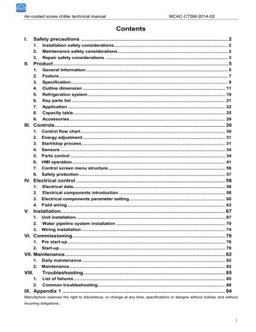
- 2 Safety precautions
- 5 Product
- 30 Controls
- 30 1. Control flow chart
- 31 2. Energy adjustment
- 31 3. Start/stop process
- 34 4. Sensors
- 34 5. Parts control
- 41 6. HMI operation
- 56 7. Control screen menu structure
- 57 8. Safety protection
- 58 Electrical control
- 60 3. Electrical components parameter setting
- 63 4. Field wiring
- 67 Installation
- 67 1. Unit installation
- 74 3. Wiring installation
- 76 Commissioning
- 76 1. Pre start-up
- 79 2. Start-up
- 82 Maintenance
- 82 1. Daily maintenance
- 82 2. Maintenance
- 85 Troubleshooting
- 85 1. List of failures
- 88 2. Common troubleshooting
- 94 Appendix
