- Sports & recreation
- Fitness, gymnastics & weight training
- NordicTrack
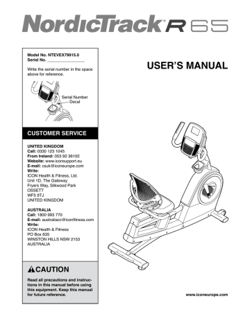
- R 65 NTEVEX79915.0
- User manual
MAINTENANCE AND TROUBLESHOOTING . NordicTrack R 65 NTEVEX79915.0
Add to my manuals
32 Pages
NordicTrack R 65 NTEVEX79915.0 is an exercise bike designed to provide an effective cardiovascular workout in the comfort of your home. With its various features, it offers a personalized and engaging fitness experience. The bike allows you to monitor your heart rate using the incorporated heart rate monitor, ensuring you stay within your target zone. Its sturdy construction supports a maximum user weight of 300 lbs (136 kg), making it suitable for users of different sizes. The adjustable seat and handlebars enable you to find a comfortable riding position.
advertisement

MAINTENANCE AND TROUBLESHOOTING
MAINTENANCE
Regular maintenance is important for optimal performance and to reduce wear. Inspect and properly tighten all parts each time the exercise bike is used.
Replace any worn parts immediately.
To clean the exercise bike, use a damp cloth and a small amount of mild soap. IMPORTANT: To avoid
damage to the console, keep liquids away from the console and keep the console out of direct sunlight.
CONSOLE TROUBLESHOOTING
If the console does not display your heart rate when you use the handgrip heart rate monitor, see step 5 on
If lines appear in the console display, see HOW TO
CHANGE CONSOLE SETTINGS on page 23 and
adjust the contrast level of the display.
If a replacement power adapter is needed, call the telephone number on the cover of this manual.
IMPORTANT: To avoid damaging the console, use only a manufacturer-supplied regulated power adapter.
HOW TO ADJUST THE DRIVE BELT
If the pedals slip while you are pedaling, even while the resistance is adjusted to the highest setting, the drive belt may need to be adjusted. Before you adjust the
drive belt, unplug the power adapter.
With the help of a second person, first place some sturdy packing materials under the frame so that the front of the frame is lifted off the floor. Have the second person hold the exercise bike to prevent it from tipping.
Next, tighten the indicated M8 Hex Nut (113) slightly to tighten the Drive Belt (not shown). Then, remove the packing material from under the frame and plug in the power adapter.
113
Repeat this process, if necessary, until the pedals no longer slip.
24
HOW TO ADJUST THE REED SWITCH
If the console does not display correct feedback, the reed switch should be adjusted. Before you adjust
the reed switch, unplug the power adapter.
Note: For clarity, the left pedal is shown removed in the drawing below.
Using a small standard (flat) screwdriver, carefully pry the left Crank
Cover (25) off the left Shield
Cover (24).
24
25
Next, remove the two M5 x
20mm Screws
(not shown).
Then, rotate the left Shield Cover out of the way.
Note: For clarity, the left shield cover is shown removed in the drawing below.
Locate the Reed Switch (35). Rotate the Left Crank
Arm (100) until a Magnet (39) is aligned with the Reed
Switch. Next, loosen the clamp screw (A), slide the
Reed Switch slightly toward or away from the Magnet, and then retighten the clamp screw.
100
A
39
35
Plug in the power adapter and rotate the Left Crank
Arm (100) for a moment. Repeat these actions until the console displays correct feedback.
When the reed switch is correctly adjusted, reattach the parts that you removed.
25
advertisement
* Your assessment is very important for improving the workof artificial intelligence, which forms the content of this project
Related manuals
advertisement