Sommer TWIST200E Sliding Gate Opener Installation and Operating Instructions
Add to My manuals32 Pages
advertisement

clos e open
46685V001-292012-0-OCE-Rev.D_GB
twist 200 E
Installation and Operating Instructions
1 - 32
Table of contents
General Information ...................................................... 3
Symbols ........................................................................................... 3
Safety instructions ............................................................................ 3
Intended use .................................................................................... 3
Improper use .................................................................................... 4
Permitted gate wing dimensions ...................................................... 4
Technical data .................................................................................. 4
Dimensions ...................................................................................... 4
Functional description ...................................................................... 4
Installation preparations ............................................... 6
Safety instructions ............................................................................ 6
Tools required ................................................................................... 6
Personal safety equipment ............................................................... 6
Scope of supply ................................................................................ 6
Potentiometer for force tolerance ................................................... 19
Button on control unit ..................................................................... 19
Light-emitting diodes (LED) ............................................................ 20
DIP switches .................................................................................. 20
Radio connector ............................................................................. 21
Automatic closing function ............................................................. 21
Connection to mains power (AC 230 V) ......................................... 21
Fuses ............................................................................................. 21
Transformer terminal ...................................................................... 22
Connecting drives .......................................................................... 22
Connecting safety device ............................................................... 22
Connecting button .......................................................................... 22
Connecting warning light ................................................................ 22
Connecting external consumers ..................................................... 23
Potential-free relay contact ............................................................ 23
Motor PCB ...................................................................................... 23
TorMinal interface ........................................................................... 23
Installation ...................................................................... 7
Tips for installation ........................................................................... 7
Drive installation position ................................................................. 7
A/B dimension table ......................................................................... 8
1. Setting the end position for gate "OPEN" ..................................... 8
2. Setting the end position for gate "CLOSE" ................................... 8
Setting the limit switches .................................................................. 9
Instructions for setting the end positions .......................................... 9
Emergency unlock for power failure and installation ........................ 9
Removing cover ............................................................................. 10
Installation of fittings ....................................................................... 10
Examples for A/B dimensions ........................................................ 10
Opening gate outwards ...................................................................11
Post or pillar fitting ...........................................................................11
Gate wing fitting ..............................................................................11
Timber post fittings ..........................................................................11
Installing the control unit ................................................................ 12
Connection to mains power (AC 230 V) ......................................... 12
Connecting drive to control unit ...................................................... 12
Programming the hand-held remote control ................................... 13
Checking the direction of running ................................................... 13
Accessories ................................................................. 24
Safety instructions .......................................................................... 24
Warning light .................................................................................. 24
Key switch ...................................................................................... 24
Photo eye ....................................................................................... 24
Connector wiring set ...................................................................... 25
Main switch .................................................................................... 25
External antenna ............................................................................ 25
Electric lock DC 24 V ..................................................................... 26
Maintenance and care ................................................. 27
Safety instructions .......................................................................... 27
Regular testing ............................................................................... 27
Miscellaneous .............................................................. 28
Disassembly ................................................................................... 28
Disposal ......................................................................................... 28
Troubleshooting .......................................................... 29
Tips on troubleshooting .................................................................. 29
Connection diagram .................................................... 31
Initial operation ............................................................ 14
General information ........................................................................ 14
Preparations for continuous operation ........................................... 14
Enabling continuous operation ....................................................... 14
Adjusting the force tolerance .......................................................... 15
Programming the hand-held remote control ................................... 15
Wiring diagram ............................................................ 32
Operation / Use ............................................................ 16
Safety instructions .......................................................................... 16
Normal mode .................................................................................. 16
Summer-winter mode ..................................................................... 16
Intermediate stop ........................................................................... 16
Obstacle detection ......................................................................... 16
Opening and closing gate .............................................................. 16
Control unit reset ............................................................................ 17
Radio receiver ................................................................................ 17
Display and button explanation ...................................................... 17
Programming the hand-held remote control ................................... 17
Deleting a hand-held remote control button from the radio receiver 18
Deleting all radio codes of a channel ............................................. 18
Deleting the radio receiver memory ............................................... 18
Connecting external antenna ......................................................... 18
Troubleshooting ............................................................................. 18
Additional functions and connections ...................... 19
Jumper ........................................................................................... 19
– 2
Symbols
General Information
¾
For automatic closing the main and auxiliary closing edges must be secured in accordance with the applicable directives and standards.
ATTEnTIOn SyMBOl:
Important safety instructions!
To ensure personal safety, it is important to observe all instructions. Save these instructions!
¾
Always remove the key to ensure that unauthorized persons cannot unlock the drive and open the gates.
nOTE SyMBOl:
Information, useful advice!
Refers to a respective picture in the introduction or main text.
Safety instructions
General
¾
These installation and operating instructions must be read, understood and complied with by persons who install, use or perform maintenance on the drive.
¾
The manufacturer does not accept liability for damage or interruptions to business resulting from non-observance of the installation and operating manual.
¾
Always ensure compliance with accident prevention regulations and current standards in each respective country.
¾
All applicable Directives and standards must be observed for installation and operation, such as: EN 12453, EN 12604, EN 12605
¾
Before working on the gate or the drive always disconnect the control unit from the power supply and lock to prevent reactivation.
¾
All electrical wiring must be firmly secured to prevent displacement.
¾
There is a risk of persons being crushed or cut by the mechanism or sharp edges of the door.
¾
Never operate a damaged drive.
¾
After installation and commissioning all users must be instructed in the function and operation of the swing gate drive.
¾
Only use OEM (Original Equipment Manufacturer) spare parts, accessories and mounting material.
Radio remote control
¾
The remote control must only be used for devices and systems in which radio interference will not endanger people, animals or objects or the risk is reduced by other safety devices.
¾
The user must be made aware that systems that pose an accident risk should only be operated – if at all – by remote control if the user can actually see the door.
¾
The radio remote control may only be used if the door’s movement can be watched and no persons or objects are within the range of movement.
¾
Store the hand-held transmitter so that unintended operation, e.g., by children or animals, is impossible.
¾
The operator of the radio system is not protected from faults due to other telecommunications equipment or devices (e.g. radio-controlled systems that are licensed to operate in the same frequency range).
If substantial interference occurs, please contact your appropriate telecommunications office which has radio interference measuring equipment (radiolocation).
¾
Do not operate the hand-held transmitter in areas with sensitive radio communications or systems (e.g. airports, hospitals).
Intended use
nOTE!
After installation of the drive the person responsible for the installation must complete an EC declaration of conformity for he gate system in accordance with the Machinery
Directive 2006/42/EC and apply the CE mark and a type plate. This is also required for private installations and also if the drive is retrofitted to a manually operated gate.
This documentation and the Installation and Operating
Instructions are retained by the operator.
Storage
¾
The drive must be stored in an enclosed, dry area at a room temperature of -20 - +70 °C.
¾
The drive should be stored horizontally.
Type plate
¾
The type plate is inside the cover of the control unit.
+70°
20°
Operation
¾
Do not allow children or persons who have not been instructed to operate the gate control unit.
¾
Open and close the gate only if there are no children, persons, animals or objects within its range of motion.
¾
Actuate the gate wirelessly only if you have an unobstructed view.
¾
Never put your hand near the gate when it is moving or near moving parts.
¾
Regularly check the safety and protection functions and repair faults when they are detected. See Care and maintenance.
¾
Drive through the gate only when it has opened completely.
¾
Set the force tolerance as low as possible.
¾
The drive is intended exclusively to open and close doors. Any other use does not constitute intended use. The manufacturer accepts no liability resulting from use other than intended use. The user bears the sole responsibility for any risk involved. It also voids the warranty.
¾
Doors automated with an operator must comply with the valid standards and directives: e.g. EN 12453, EN 12604, EN 12605.
¾
Maintain the safety clearances between the gate and surroundings as specified in EN 12604.
¾
The drive must be in good technical condition, and it must be used for its intended purpose with awareness of the hazards as described by the installation and operating manual.
¾
Faults that may affect safety must be repaired without delay.
¾
The gate must have very little play in the hinges.
¾
The gates must be stable and resistant to twisting, i.e. they must not bend or twist when opening and closing.
¾
The DSTA24 control unit and the twist 200 drive must only be used together.
¾
The DSTA24 control unit and the twist 200 drives are designed for private use.
¾
The electric drive is designed exclusively for opening and closing one or two-wing swing gate installations.
– 3
General Information
Improper use
¾
Opening or closing flaps, e.g. for access to roofs or similar.
Dimensions
All dimensions are in millimeters.
¾
Operation with 2x twist200E, EL, on one wing is prohibited.
¾
Mixed operation with 1 x twist 200 E, EL, and 1 x twist XL is permitted only in combination with the twist XS # 3248V000 conversion kit.
Permitted gate wing dimensions
52
Length:
Height:
Weight:
Open area: min. 0.8 m …max. 2.5 m max. 2.5 m max. 200 kg min. 50 %, regardless of wing size
Gate inclination: 0 %
53
53
23
With lift gates
nOTE!
Risk of injury with lift gates that are not balanced!
Gates that lift must be optimally balanced to ensure that they cannot accidentally fall closed when not locked!
106
nOTE!
The twist 200E must not be operated with a lift gate except in combination with the 3129V001 (left wing of gate) and
3129V003 (right wing of gate) gate brackets!
• Weight:
• Length:
• Gate inclination:
Technical data
max. 120 kg max. 2.5 m max. 10 %
1-wing 2-wing Unit
General
Runtime depending on A/B size
Protection type
Drive
Controller housing
Rated voltage
Rated frequency
Operating temperature range
Drive approx.
10 …22
IP 44
IP 65
220 …240
50 approx.
15 …27
IP 44
IP 65
220 …240
50 seconds
AC/V
Hz
-30 +70 -30 +70
°C
Controller housing
Lift (per drive)
Max. tension and compress. force
-30 +70
390
2000
-30 +70
390
2000
°C mm
N
Duty cycle:
Stand by
15
Rated current consumption 20
Rated wattage
Rating
Motor voltage:
2,2 approx. 22
Rated current consumption: approx. 3
15
20
2,2 approx. 20 approx. 6
% mA
W
DC/V
A
Rated power consumption: approx. 118 approx. 234 W
Workplace-related emission value < 75 dBA – drive only
Cmin.
106
0
110
0
670 - Cmax.
min.
710 - max.
177
185
17
Functional description
nOTE!
The end positions (gate OPEn + ClOSE) are set by internal limit switches in the drive and detected during operation.
The gate wing is opened and closed by retracting and extending the gate operator. When the defined end positions are reached the drive is automatically switched off by the limit switch.
Closing the gate
nOTE!
An end stop at the "gate ClOSED" end position is absolutely essential. An electric lock can be installed as an additional lock.
The gate wing does not require a lock, because the drive is self-locking
(retained by the control unit). The gate cannot be pushed open manually without damaging the drive or the fittings.
Wireless actuation
The drive can be actuated with the included hand-held transmitter once the transmitter has been set to the radio receiver.
Safety devices
The control system has an automatic force monitor. If the drive requires more force for opening or closing than the value saved during the learning run, the drive stops and reverses (gate "CLOSE" direction) or remains stationary (gate "OPEN" direction).
Various safety devices can be connected to the control unit (see additional functions and connections).
e.g.
• Photo eye
• Safety contact strip with additional evaluation unit
– 4
General Information
Declaration of Installation
for the installation of an incomplete machine in accordance with the Machinery Directive 2006/42/EC, appendix II, part 1 B
SOMMER Antriebs- und Funktechnik GmbH
Hans - Böckler - Straße 21 - 27
73230 Kirchheim unter Teck
Germany hereby declares that the control unit twist 200 E as of the identifi cation twist 200 E 01/10 complies with the Machinery Directive 2006/42/EC and is specifi ed for installation in a door system.
• The following fundamental safety requirements in accordance with appendix I have been applied and observed:
- General principles no. 1
- 1.2 Safety and reliability of control units
Safety input I terminal 17 + 18: Cat 2 / PL C
Internal force limitation Cat 2 / PL C
Safety categories in accordance with EN 13849 - 1:2008
• Compliant with the regulations of the EC Building Products Guideline 89/106/EC.
For the operating forces part, the respective initial testing has been carried out in consultation with recognized inspecting authorities. In doing so, the harmonized standards EN 13241-1, EN 12453 and EN 12445 have been applied. For the tested combinations, refer to the table "Reference list" on the Internet under www.sommer.eu.
• Compliant with the Low Voltage Directive 2006/95/EC.
• Compliant with the Directive on Electromagnetic Compatibility 2004/1 08/EC.
• The technical documentation was drawn up in accordance with appendix VII B.
The product may only be put into operation after it has been established that the door system complies with the regulations of the Machinery Directive.
29.12.2009
Jochen
Responsible
EU Declaration of Conformity
SOMMER Antriebs- und Funktechnik GmbH hereby declares that the twist
200 E gate drive and the SOMMER Antriebs- und Funktechnik GmbH hand-held radio transmitter conform to the basic requirements and the other applicable regulations of Directive 1999/5/EC.
The Declaration of Conformity is available at the following web site: www.sommer.eu/mrl
– 5
Safety instructions
Installation preparations
Scope of supply
¾
Check the package before installation to avoid unnecessary work and expense if a part is missing.
nOTE!
The control unit is supplied with a mains cable for use in installing the drives only. On completion of installation disconnect the mains cable and replace it with permanent wiring. The mains cable is not approved for constant or outdoor operation.
¾
The actual scope of supply may vary depending on the design of the drive.
7 2 nOTE! DAnGER OF DESTRUCTIOn By VOlTAGE
FlUCTUATIOnS.
Voltage fluctuations e.g.: caused by welders may destroy the control unit.
Do not connect the control unit to the mains until all installation work is completed.
5
6
8
3
¾
Install all wiring for the drive in ducts approved for the purpose (e.g. for underground installation).
9
¾
The control unit must be connected to the power supply by an electrician only.
clos e open
SOMM
NTR
ER
IEBE
¾
Installation must be in accordance with the installation and operating manual.
twis t 200 ge- u nd B edien D ungs anleit ung
¾
Remove or disable locking devices (electric locks, bars etc.) before installing the drive.
1 4
¾
Ensure that the drive is securely fastened to posts, pillars and gate wing to withstand forces generated when opening and closing the gate.
¾
Cover or remove the drive when welding fittings to posts or gate wing to prevent damage from sparks or welding beads.
Complete set
Weight
1-wing
9,1
2-wing
13,8 kg
¾
If a button is used for opening or closing, it must be installed at a height of at least 1.6 m to prevent operation by children.
Package (L x W x H):
1. Installation and Operating
Instructions
800 x 200 x 220
1 x 1 x mm
¾
Use only approved fasteners (e.g. wall plugs) in public areas.
2. Drive with cable 1 x 2 x
Tools required
3. Control unit in housing
(incl. radio receiver, transformer and power plug)
1 x 1 x
14 mm
8 mm
M10 8,2 mm 2x 17 mm
4. Hand-held transmitter with battery 1 x
5. Fittings for gate wing 1 x
6. Fittings for post or pillar
7. Stainless steel hex bolt M10x45
1 x
2 x
8. Stainless steel locknut M10
9. Plug
2 x
2 x
1 x
2 x
2 x
4 x
4 x
4 x
Personal safety equipment
¾
Safety glasses (for drilling)
¾
Work gloves
– 6
10
8
E S
P
S
C
M
C
M
Installation
3
1
2
4 x 0,75 mm
2
2 x 0,75 mm 2
ME
R
TOR
ANT
RIEB
E
6
O
5
3 x 1,5 mm 2
AC 230V
4 x 0,75 mm
2
3
2 x 0,75 mm
2
4
2 x 0,75 mm 2
7
9
Tips for installation
• Define the installation location together with the operator.
• Do not install the housing where it could be seen from the street, otherwise the housing and control unit may be damaged by vandalism.
• If the gate wings are larger than 2 m or there are two wings, attach a threshold or a threshold bar to the gate.
nOTE!
Additional pulse transmitters are: hand-held transmitters,
Telecody, wireless indoor switches and key switches. In the case of the hand-held transmitter, Telecody or the wireless indoor switches a connecting line to the drive is not required
(contact your dealer).
1.
Warning light DC 24 V
2.
Key switch (1 or 2 contact)
3.
Photo eye
4.
Connector wiring set 7 m
5.
Main switch (lockable)
6.
rod antenna (with cable)
7.
Electric lock DC 24 V
8.
Telecody
9.
Car/wall holder for hand-held transmitter
10. Timber post fittings
Drive installation position
Install drive horizontally. Note installation position of motor; it must always point upright.
– 7
A/B dimension table
Installation nOTE!
Before installation define the A/B dimensions. Without them the drive cannot be correctly installed and operated.
nOTE!
Select A/B dimensions so the desired opening angle is reached. The specified opening angle (D) is a reference value for the largest possible angle.
If the gate wings are larger than 1.5 m, the B dimension must be at least 140 mm.
• Note different post or pillar dimensions.
140
160
180
200
A
W D
100
120
220
240
260
80
90°
90°
90°
90°
90°
90°
90°
90°
90°
100
100°
100°
100°
95°
95°
95°
95°
95°
120
110°
105°
105°
105°
100°
100°
100°
140
115°
115°
110°
110°
105°
105°
95°
160
125°
120°
115°
115°
110°
100°
90°
180
130°
125°
115°
110°
100°
90°
200 220 240 260
120°
110°
105°
100°
95°
110°
105°
100°
95°
105°
100°
95°
90°
100°
95°
90°
• Dimensions A, B in mm
• D = largest possible opening angle in degrees
• 1 revolution = 1.25 mm adjustment path when adjusting the limit switch
nOTE!
Follow these instructions to set the end positions.
This ensures that:
• the drive is at maximum rigidity in the ClOSED position
• the maximum possible path is fully used
• only one limit switch (ClOSED position) must be set
1. Setting the end position for gate
"OPEn"
2. Setting the end position for gate
"ClOSE"
A
B
C1 =
430 mm
C = 1060 mm
D
= 670
nOTE!
End position gate “ClOSE” preset, approx. C1 = 430 mm.
This corresponds to the maximum possible value for C1 or
Cmax. Do not exceed maximum values for C1 = 430 mm and
C = 1060 mm.
1. Close the gate manually. Unlock the drive to allow this (see "Unlocking the drive", page 9).
2. Measure dimension C1 on drive and check that C1 is no greater than
C1max = 430 mm.
3. Set dimension C1. See "Setting the limit switches".
4. Connect the control unit to the preinstalled plug and connect the drive
(see "Connecting drive to control unit").
nOTE!
Gate "OPEn" end position preset, approx. C1 = 40 mm.
1. Measure A and B dimension and compare with preset values from A/B dimension table.
2. Install the post fitting on post in accordance with the selected A/B dimensions.
3. Move the gate to the desired OPEN position. Note the maximum possible opening angle D from the A/B dimension table.
4. Remove drive from package and attach to post fitting. The drive at maximum retraction as delivered.
5. Fasten drive temporarily to gate with gate fitting, e.g. with a clamp.
6. Set gate "AUF/open" end position. See "Setting the end switches"
– 8
Installation
Setting the limit switches
nOTE!
Before setting the limit switches read the "Information on setting the end positions".
If the information and instructions are not observed the drive and control unit may be irreparably damaged.
Gate ClOSE
close open clos e clos e open
Gate OPEn
open clos e open close open
nOTE!
Always reposition the limit switch connector cable after adjustment to prevent it from being jammed in the gate operator.
Emergency unlock for power failure and installation
nOTE!
Actuate the emergency lock only with the control disconnected from the power and locked to prevent reactivation.
In case of power failure the gate can be opened or closed manually after unlocking the drive, regardless of its position.
Unlocking the drive
11
Instructions for setting the end positions
nOTE!
Do not adjust limit switches with a battery-powered screwdriver or a similar tool. This may destroy the limit switches.
nOTE!
never connect drive to 230V. This will destroy the motor immediately.
nOTE!
Before installation set the limit switches for "gate OPEn" and
"gate ClOSE". The gate wing must not come into contact with the housing, or it may be damaged.
6
13 12
7
36
1. Turn key (6) 90° clockwise - this unlocks the emergency release bracket (11).
2. Pull the emergency release bracket (11) away from the housing (12), the motor (7) is pulled down from the spindle (13). The springs (36) push the motor (7) down off the spindle (13).
Make unlocking easier: move gate wing manually.
– 9
locking the drive
1. Proceed in reverse order of emergency unlock.
Installation
Steel posts
Note the thickness of the post.
The fitting can be welded or bolted directly to steel posts.
nOTE!
The emergency release bracket (11) must be almost in contact with the housing (12). If the drive is not completely unlocked, it will damage the motor (7).
Brick or concrete pillars
When attaching the fitting to the brick pillar, ensure that the holes are not too close to the edge of the pillar. The distance may vary depending on the type of plug. The plug manufacturer will provide recommended distances.
11 12 13
Timber posts
The included fitting can be used, because the forces are not excessively large.
If the included fitting cannot be used with your gate, contact your dealer for special fittings (e.g. wood post fitting).
nOTE!
After installation of fittings do not do any more welding or grinding. Residues of such work will result in rapid corrosion of fittings.
Removing cover
nOTE!
Remove the cover only with the control unit disconnected from the power and locked to prevent reactivation.
Installation of fittings
nOTE!
The strength of the included fittings is designed for the drive
(twist 200). If other fittings are used, the warranty will not apply.
nOTE!
If the B dimension is smaller than the smallest B dimension in the table, install a spacer plate under the post fitting to ensure that the B dimension is at least 100 mm (see A/B dimension table).
¾
Cover or remove the drive when welding fittings to posts or gate wing to prevent damage from sparks or welding beads.
¾
Attach fitting to thick brick or concrete pillar so the wall plugs cannot come loose during operation. Adhesive-bonded anchors, with which a threaded pin is cemented to the brickwork without tension, are more suitable than steel and plastic expanding plugs.
¾
Clearances between the gate wing and post or gate wing and drive must be maintained in accordance with the applicable standards.
Examples for A/B dimensions
1. Small post
A
=
80
100
100
17
B
=
110
Assumed:
Steel post 100 mm x 100 mm desired opening angle min. 90° wing length 1.5 m
Measured:
A = 80 mm
B = 110 mm
According to table
A = 80 mm
B = 120 mm
Opening angle = max. 94°
2. long post
A
=
225
215
100
78
B
=
165
Assumed:
Concrete pillar 215 mm x 100 mm desired opening angle min. 95° wing length 2.5 m
Measured:
A = 225 mm
B = 165 mm
According to table
A = 220 mm
B = 160 mm
Opening angle = max. 91°
– 10
3. Angle/hinge inside
B =
10
0
A = 100
195
100
Installation
Gate wing fitting
Because the B dimension is less than
100 mm, install a spacer under the post fitting. This means that the B dimension is 100 mm.
According to table
A = 100 mm
B = 100 mm
Opening angle = max. 105°
70
50
8,5 18,5
37
3
Opening gate outwards
>120mm
30
40
10
10
1. Close door
2. Mount fitting on the gate operator of the drive, insert bolt from above.
3. Clamp the fitting to the gate wing and check the end position setting of the limit switch with a test movement.
4. Check that the drive is horizontal in three positions:
▫ Gate "CLOSE"
▫ Gate "OPEN"
▫ Gate opened 45°
5. Position of fitting OK, fix fitting to gate wing.
6. Tighten the nut on the bolt so the drive can still be easily rotated.
Timber post fittings
Available as an accessory.
ATTEnTIOn
Depending on the actual installation the passage width will be reduced by about 150 mm on each side, because the drives project into the passage.
The A/B dimensions must each be at least 120 mm.
¾
Prepare the post or pillar fitting on site. It must always be fitted to the actual dimensions of the post or pillar.
Post or pillar fitting
A = 95
100
78
30
6
80
92
104
113
100
100
73
B = 160
A = 95
100
100
73
B = 166
100
78
8
10
2. Height from ground to bottom of fitting min. 50 mm. This may be restricted by the fastening options of the drive to the gate wing.
3. Tighten the nut on the bolt until the drive can still be easily rotated.
– 11
Installing the control unit
Installation
Connection to mains power
(AC 230 V)
nOTE!
The drive is supplied with a mains cable for use in installation only. On completion of installation disconnect the mains cable and replace it with permanent wiring. The mains cable is not approved for constant or outdoor operation.
nOTE!
Approved wire cross sections for all terminals:
1 mm² - 2.5 mm².
M
N e t z
nOTE!
Connect the mains connection according to En 12453 (allpole line disconnector). Install a lockable main switch (allpole shut-off) to prevent the power from being accidentally switched on during maintenance work. See accessories, main switch on page 25.
Use a suitable power cable with a fuse (16 A, slow-blow).
1
2
230V
AC
L
3
N
4
PE
PE
B
C
D
Terminal
1
2
3 + 4
Description Function
L
N
PE
Mains supply line AC 230 V
Neutral wire
Protective ground
nOTE!
The control unit must be connected to mains power by an electrician.
6x M16
3x M20
B
C
D
E
Size
A
Housing 2
250 mm
75 mm
175 mm
160 mm
235 mm
ATTEnTIOn DAnGER OF DESTRUCTIOn By WATER
Penetration of water may destroy the control unit. Use the fixture points provided for screwing on the housing. Do not drill through the rear wall of the housing. The housing is not sealed, water will penetrate and the control unit will be destroyed.
¾
Disconnect the power to the control unit before working on it.
¾
Dry any moisture that enters the housing with a fan.
¾
The control unit must be connected to the power supply by an electrician only.
¾
Install the control unit housing in a perpendicular position with the wire feed at the bottom without strain to prevent penetration of water and the cover is watertight.
Connecting drive to control unit
IMPORTAnT!
never connect drive directly to 230 V. This will destroy the motor immediately.
ATTEnTIOn
Connect the drives only with the control unit disconnected from the power and locked to prevent reactivation.
Gate 1 wing
nOTE!
Connect 1-wing drive to terminal M2 only.
2-Fl
.
Kraf t
3
P1
Netz
6
0
SH
Zu
LED
6
LED
1
LED
4
9
LED
LED
3
5
LED
LED
Imp
.
2
Imp
.
Ge h
ON
1-Fl
.
M2
7
8
5
6
M1
9 1
0
0V
M2
13
14
11
12
24V
24VWarn licht
M2
– 12
Gate 2 wing
2-Fl
.
Kraf t
3
P1
Netz
6
0
Zu
6
LED
LED
1
LED
4
9
SH
5
LED
LED
Imp
.
2
LED
Imp
.
LED
7
3
Ge h.
G e h
ON
1
2
OF
F
1-Fl
.
M1
Installation
Checking the direction of running
¾
After the first command the drive must traverse in the gate "OPEN" direction. If the drive traverses to gate "CLOSE", reverse the drive connector cable at the control unit.
M2
Gate 1 wing
5
6
7
8
11
1
9 10
0V
M2
24V
24VWarnlicht
Imp
M1
M1
M2
8
1x
M2
1. Connecting drive to control unit
▫ First connect and adjust the drive for the gate with stop (M1) and then the drive for the walk-through gate (M2).
2. Set all DIP switches to “OFF”.
3. Set jumpers: 1 or 2-wing gate system
4. Connect control unit to the power supply.
⇒ "Mains" LED lights and "WL" LED flashes.
Gate 2 wing
7
8
5
6
M1
9 1
0
0V
M2
11
12
24V
13
14
24VWarn licht
M2
Programming the hand-held remote control
nOTE!
Before programming the hand-held transmitter for the first time, always clear the radio receiver memory completely.
1x
M1
2.
1.
M2
5
2
3
5
6
7
M1
8
13
14
11
12
9 1
0V
M2
0
24V
24VWarnlicht
M1
5
6
7
M1
8
13
14
11
12
9 1
0V
M2
0
24V
24VWarnlicht
M2
1
4
5
6
1. Press the Learn button (1).
▫ 1 x for channel 1; LED (K1) lights.
▫ 2 x for channel 2; LED (K2) lights.
2. Press the desired hand-held transmitter button (5) until the LED is off.
▫ Depending on which channel that has been selected. The hand-held transmitter has transferred the radio code to the radio transmitter.
⇒ LED extinguishes - programming is finished.
Terminal
5 + 6
7 + 8
Description Function
M1 • 1 wing: no function
M2
• 2 wing: Connection for motor-1
The motor must be on the gate wing that opens second or on which there is an outside stop bar.
• Terminal 5: motor wire brown
• Terminal 6: motor wire blue
• 1 wing: Connection for the motor
• 2 wing: Connection for motor-2
The motor must be on the gate wing that opens first or on which there is no outside stop bar.
• Terminal 7: motor wire brown
• Terminal 8: motor wire blue
nOTE!
If no radio code is sent within 10 seconds, the radio receiver switches to normal operation.
3. Canceling the Learn mode: Press the Learn button (1) until no more
LEDs are lit.
4. Programming additional hand-held remote controls. Repeat the above steps. A maximum of 112 memory slots is available.
– 13
General information
Initial operation nOTE!
Always run learning procedure under supervision, because the drives traverse at full power and half speed. This is dangerous for persons, animals and object within the range of motion of the gates.
¾
"WL" LED or a connected warning light will flash during the learning procedure as a visual warning independent of the setting of DIP switch 4.
Run learning procedure at least twice:
LE
LED
2
G
4
ED
9
1
LED
Imp
.
Imp
.
Geh.
DIP
5
6
ON
1
2
3 4
¾
In the commissioning process the force required for opening and closing, the runtime and the closing delay are learned and saved by the control unit.
OFF
¾
If the learning run is interrupted by a stop before completion ("WL" LED lights when opening or closing), all previously saved values are lost.
7
8
Preparations for continuous operation
ATTEnTIOn! DAnGER OF SHORT-CIRCUIT!
Before switching the DIP switches, disconnect the power supply to the control unit.
P1
Netz
6
0
Zu
6
LED
LED
1
LED
4
9
SH
LED
7
LED
3
5
LED
LED
Imp
.
2
Geh.
Imp
.
Geh.
ON
1
OF
F
2
3 4
DIP
7
5 6
8
M1
2.
1.
1. Selection 1 or 2-wing, desired components connected and settings made, see additional functions and connections.
2. Mains power connected and voltage (AC 230 V) at control unit
("Mains" LED on).
3. Fittings bolts tightened, drives can be moved easily.
4. Position cover and click into place.
5. Set emergency unlock and lock with padlock.
6. Close door
Enabling continuous operation
• Check the setting of the limit switches. Open and close gate. If the drive switches off correctly at both end positions, run learning procedure.
nOTE!
Set DIP switch 8 to "On" and leave in this position.
"WL" LED flashes until the force values, runtimes and closing delays are learned and saved.
2-wing gate system!
Gate wing 1 (M1 gate with stop) closes first, then gate wing 2 (M2 walkthrough gate), this prevents an incorrect closing sequence for gates with different runtimes.
T
1A
1. Press (Imp) button, drive traverse to gate "OPEN" end position.
⇒ "Mains" LED lights, "WL" LED flashes.
nOTE!
After the first command the drive must traverse in the gate
"OPEn" direction. If the drive traverses to gate "ClOSE", reverse the drive connector cable at the control unit.
P1
Netz
6
0
Zu
6
LED
LED
1
LED
4
9
SH
LED
7
LED
3
5
LED
LED
Imp
.
2
Geh.
Imp
.
Ge h.
ON
1
OF
F
2
3 4
DIP
7
5 6
8
M1
1.
2.
M2
M2
F
FUS
U
2. Press (Imp) button, drive traverses to gate "OPEN" end position.
⇒ "Mains" LED lights, "WL" LED flashes.
3. Repeat item 1 + 2.
⇒ "WL" LED stops flashing, all values learned and saved.
At the next command the gates are started and stopped with soft running.
Every time the gates are opened the control unit monitors the force, runtime and closing delay and adjusts them incrementally when the end position is reached.
nOTE!
If the learning procedure is not correctly completed (drives traverse without soft running, "Wl" lED flashes), reset the control unit (delete saved values, see control unit reset) and run the learning procedure again.
– 14
Initial operation
Adjusting the force tolerance Programming the hand-held remote control
nOTE!
After installation of the drive the person responsible for the installation must complete an EC declaration of conformity for the gate system in accordance with the Machinery Directive
2006/42/EC and apply the CE mark and a type plate. This is also required for private installations and also if the drive is retrofitted to a manually operated gate. This documentation and the Installation and Operating Instructions are retained by the operator.
nOTE!
Before programming the hand-held transmitter for the first time, always clear the radio receiver memory completely.
5
2
3 nOTE!
The adjustment of the force tolerance is safety-relevant and must be performed by qualified personnel with upmost care.
If the force tolerance is too high, persons or animals may be injured and objects damaged.
Select the force tolerance as low as possible to ensure that obstacles are detected quickly and safely.
5
4
6
1
• Maximum force = learned force + force tolerance (adjustable with the potentiometer).
• If the force is not sufficient for opening or closing the gate completely, increase the force tolerance by rotating the potentiometer clockwise.
• If the setting is changed while the gate is opening or closing, the control unit imports the setting next time the gate is opened.
• After setting the force tolerance it may be necessary to reset the end positions.
Deleting the radio receiver memory
1. Press and hold the Learn button (1).
⇒ After 5 seconds the LED flashes - after another 10 seconds the LED is steady.
⇒ After a total of 25 seconds all LEDs light.
2. Press the learn button (1).
⇒ All LEDs off - clearing process complete.
Checking the force tolerance
See Care and maintenance / regular testing.
Setting the force tolerance to the automatically learned force.
The potentiometer setting is imported again at every start.
Kraf t
P1
Net z
6
Au f
6
LED
LED
1
LED
4
LED
3
5
LE
D
Imp
LED
.
2
Geh.
Imp
.
Geh.
DIP
7
8
F
F
3
9
5
6
2-Fl
.
0 ON
1
2
3 4
• Left stop of potentiometer (0) is the lowest tolerance, the right stop (9) is the highest tolerance.
1A
U
• Insert plugs.
close open
Programming the hand-held remote control
Gate system 1-wing:
• Button 1 on radio channel 1
Gate system 2-wing:
• Button 1 on radio channel 1 (both gate wings open)
• Button 2 on radio channel 2 (only the walk-through gate opens)
1. Press the Learn button (1).
▫ 1 x for channel 1; LED (K1) lights.
▫ 2 x for channel 2; LED (K2) lights.
2. Press the desired hand-held transmitter button (5) until the LED is off.
▫ Depending on which channel that has been selected. The handheld transmitter has transferred the radio code to the radio transmitter.
⇒ LED extinguishes - programming is finished.
3. Canceling the Learn mode: Press the Learn button (1) until no more
LEDs are lit.
nOTE!
If no radio code is sent within 10 seconds, the radio receiver switches to normal operation.
Control
1. Press button 2, walk-through gate wing opens.
2. Press button 1, both gate wings open.
3. Repeat the above steps to program additional hand-held transmitters.
▫ The radio receiver can save a maximum of 112 different radio codes (hand-held transmitter buttons).
– 15
Safety instructions
¾
Never operate a damaged drive.
Operation / Use
Opening and closing gate
¾
Children, persons, animals or objects must not be within the range of motion of the gates during opening or closing.
¾
Do not operate the hand-held transmitter in areas with sensitive radio communications or systems (e.g. airports, hospitals, etc.).
Requirements:
• Set DIP switch 8 set to "ON" and learning run completed.
• Hand-held transmitter (button 1 on channel K1, button 2 on channel K2) programmed.
¾
Actuate the gate wirelessly only if you have an unobstructed view of it.
¾
Store the hand-held transmitter so that unintended operation, e.g., by children or animals, is impossible.
¾
Use the radio remote control only if a non-hazardous force tolerance is set. Set the force tolerance low enough to eliminate any danger of injury by the closing force.
normal mode
The force required for opening and closing may be affected by changes to the gate as a result of damage, moisture absorption, ground subsidence, outside temperature, etc.
If the force required for opening or closing increases within the defined tolerance on the potentiometer, the new value is automatically learned by the control unit. The control unit also learns a reduced force requirement in the same way.
Summer-winter mode
Weather differences between summer and winter mean that the drive requires different forces for opening or closing the gate. If the gate will not open or close, reset the control unit and run a new learn procedure.
Temperature differences between summer and winter may means that the gate wings have different end positions, which must be compensated by adjusting the limit switches.
Intermediate stop
2-wing gate system:
Open the gate wing with the pulse command and then send the stop command. If gate wing 1 has not yet opened, the open walk-through gate wing can only be closed with the walk-through gate command.
Obstacle detection
nOTE!
Obstacle detection requires a correctly completed learning run and correctly set force tolerance.
If the gate wing contacts an obstacle when opening or closing, this is detected. The gate wing will react differently depending on the direction of motion and the settings of the DIP switches. The direction of motion following a detected obstacle is always away from it.
1x
Kra ft
P1
Ne tz
6
3
0
6
LED
LED
1
LED
4
9
S H
LED
7
3
5
LED
LED
Imp
.
2
LED
Ge h.
Imp
.
ON
Ge h.
1
2
3 4
OF
F
DIP
5 6
7
8
1-F l.
Process 1-wing
1. Press button (Imp) or hand-held transmitter (button 1)
2. Gate opens to gate "OPEN" end position
⇒ "OPEN + WL" LED on
⇒ Gate "OPEN" end position reached - LED "OPEN + WL" off
Process 2-wing - both gate wings
1. Press button (Imp) or hand-held transmitter (button 1)
⇒ Gate wing 2 (M2/walk-through gate) opens first and then gate wing
1 (M1) after a delay of 3 seconds - LED “OPEN + WL” is on.
⇒ Gate "OPEN" end position reached - LED "OPEN + WL" off
2. Press button (Imp) or hand-held transmitter (button 1)
⇒ Gate wing 1 (M1) closes first and then gate wing 2 (M2/walkthrough gate) after a delay of 5 seconds - LED “CLOSE + WL” is on.
⇒ Gate "CLOSE" end position reached - LED "CLOSE + WL" off.
Process 2-wing - walk-through gate
1. Press button (walk-though) or hand-held transmitter (button 2)
⇒ Gate opens to gate "OPEN" end position - LED "OPEN + WL" on.
⇒ Gate "OPEN" end position reached - LED "OPEN + WL" off
2. Press button (walk-though) or hand-held transmitter (button 2)
⇒ Gate closes to gate "CLOSE" end position - LED "CLOSE + WL" on.
⇒ Gate "CLOSE" end position reached - LED "CLOSE + WL" off.
– 16
Operation / Use
Control unit reset
The control unit reset deletes all programmed values (e.g. force values: force required by drive to open or close the gate, closing delay). It may be necessary to reset the control unit to delete the saved values and reprogram the unit.
Display and button explanation
5
2
4
2-F l.
Kra
3 ft
P1
Netz
6
0
Auf
Zu
6
LED
LED
1
LED
4
9
WL
S H
LED
7
LED
3
5
LED
LED
Imp
.
2
Geh.
Imp
.
ON
Ge h.
1
2
3 4
OF
F
DIP
5 6
7
8
1-F l.
1. Press and hold the button (pulse + walk-though).
⇒ "WL" LED flashes.
2. "WL" LED off - all values deleted. Release button.
⇒ "WL" LED flashes.
F
FUSE
T 1
A
U N
3. Run learning procedure again, see activating continuous operation.
K
Radio receiver
HOMElInk-COMPATIBlE
If your vehicle is equipped with a Homelink system
(Version 7), our drive and radio receiver with 868.6 MHz are compatible. Another radio frequency (40.685 or 434.42 MHz) must be used with older Homelink systems. For information see: "http://www.eurohomelink.com"
5
6
Programming the hand-held remote control
nOTE!
Before programming the hand-held transmitter for the first time, always clear the radio receiver memory completely.
3
1
1 Learn button
2 Internal antenna
3 LEDs: show which channel has been selected.
K1 = channel 1 -> same function as pulse button
K2 = channel 2 -> same function as walk-through button
! K3 = channel 3 -> no function
! K4 = channel 4 -> no function
4 Connection for external antenna (6)
Use an external antenna if the range with the internal antenna is not sufficient. See accessories
5 Hand-held transmitter button
6 External antenna
Safety instructions
¾
The operator is not protected against interference caused by other telecommunications equipment or devices (e.g. wireless systems which are being operated properly in the same frequency range).
¾
Replace the hand-held transmitter unit's batteries if you experience reception problems.
1. Press the Learn button (1).
▫ 1 x for channel 1; LED (K1) lights.
▫ 2 x for channel 2; LED (K2) lights.
2. Press the desired hand-held transmitter button (5) until the LED is off.
▫ Depending on which channel that has been selected. The hand-held transmitter has transferred the radio code to the radio transmitter.
⇒ LED extinguishes - programming is finished.
nOTE!
If no radio code is sent within 10 seconds, the radio receiver switches to normal operation.
3. Canceling the Learn mode: Press the Learn button (1) until no more
LEDs are lit.
4. Programming additional hand-held remote controls. Repeat the above steps. A maximum of 112 memory slots is available.
– 17
Operation / Use
Deleting a hand-held remote control button from the radio receiver
Deleting the radio receiver memory
If a hand-held transmitter is lost, all channels in the radio receiver must be deleted for security reasons!
After that, reprogram all hand-held transmitters in the radio receiver.
If a user moves to a group garage unit and wishes to use the hand-held transmitter with it, all radio codes in the transmitter must be deleted from the radio receiver.
1. Press and hold the Learn button (1).
⇒ After 5 seconds the LED flashes - after another 10 seconds the LED is steady.
nOTE!
For safety reasons every button and all button combinations must be deleted from the hand-held transmitter.
⇒ After a total of 25 seconds all LEDs light.
2. Release the Learn button (1).
⇒ All LEDs off - clearing process complete.
1. Press the learn button (1) and hold it down for five seconds until any
LED flashes.
Connecting external antenna
2. Release the learn button (1) - the radio receiver is in delete mode.
3. Press the button on the hand-held transmitter corresponding to the radio code you want to delete - LED goes off. The deletion procedure is ended.
¾
The antenna cable may not exert any mechanical force on the radio receiver; provide for stress relief.
⇒ LED off - wipe procedure complete.
Deleting all radio codes of a channel
1. Press and hold the Learn button (1).
▫ 1 x for channel 1; LED (K1) lights.
▫ 2 x for channel 2; LED (K2) lights.
⇒ The LED lights depending on the channel that has been selected.
⇒ After 5 seconds the LED flashes - after another 10 seconds the
LED is steady.
2. Release the Learn button (1) - the deletion procedure is ended.
Troubleshooting
All lEDs flashing:
• Attempt to set more than 112 memory slots on the radio receiver.
If additional hand-held transmitters are to be programmed, delete other hand-helds from the receiver first.
lED on:
• Learn mode: radio receiver is waiting for a radio code from a hand-held transmitter.
• radio receiver is receiving a radio code from a hand-held transmitter.
– 18
Additional functions and connections
Jumper
Selection of gate system, 1 or 2-wing
Button on control unit
Au
nOTE!
After moving the jumper reset the control unit and run a learning procedure again.
Kraf t
3
P1
Net z
6
6
LED
LED
1
LED
4
9
LED
3
5
LED
LED
Imp
.
2
Geh.
Imp
.
Geh.
1
2
3 4
5
DIP
6
7
8
2-Fl.
0
ON
2-Fl
.
label
2-Fl. / 1-Fl.
Kraf t
3
P1
Net z
6
Au f Z u
SH
LE
6
LED
LED
1
LED
4
Im
9
0
1-Fl
.
2-Fl
.
Function
Jumper on top pins = 2-wing
Jumper on bottom pins = 1-wing
Jumper not plugged in = 1-wing
Kraf t
3
Au f Z u
SH
P1
Netz
6
LE
6
LED
LED
1
LED
4
Im
9
0
1-Fl
.
label
Pulse
Walk-through
Function
Pulse button: opens both gate wings
Actuating the pulse button while the walk-through gate is moving stops it.
If the walk-through wing is open, the pulse button also open gate wing 1.
Function sequence: Open - Stop - Close - Stop -
Open …
Walk-through button: opens walk-through wing only
Walk-through button opens gate wing 1 only on a 2-wing gate. Gate wing 2 always opens first in gate systems with the stop bar outside.
Function sequence: Open - Stop - Close - Stop -
Open …
nOTE!
Button (walk-through) operates only if wing 1 is fully closed.
F
U
F
1A
Potentiometer for force tolerance
Au f
Kraf t
3
P1
Net z
6
6
LED
LED
1
9
LED
4
5
LE
D
LED
Imp
.
2
LED
3
Geh.
Imp
.
Geh.
DIP
6
7
8
5
2-Fl
.
0 ON
1
2
3 4
Setting the force tolerance to the automatically learned force.
The potentiometer setting is imported again at every start.
• Left stop of potentiometer (0) is the lowest tolerance, the right stop (9) is the highest tolerance.
F
U
Control unit reset:
To reset the control unit to the factory settings (RESET), press and hold both buttons simultaneously for 5 seconds - until LED (WL) is out.
F
1A
– 19
Additional functions and connections
light-emitting diodes (lED) DIP switches
Show the status of the control unit.
nOTE!
Before switching the DIP switches, disconnect the power supply to the control unit then switch it on again.
2-Fl
.
Kraf t
3
P1
Net z
6
0
WL
SH
Au f Z u
6
LED
LED
1
LED
4
9
LED
7
3
LED
5
LED
LED
Imp
.
2
Geh.
Imp
.
Geh.
ON
1
2
3 4
5
DIP
6
7
8
F
U N
FUSE
T
1A
K
Factory setting: OFF
Kraft
3
P1
0
6
9
Imp
LE
.
Imp
.
ON
Ge h.
1
2
OFF
3 4
5
DIP
6
7
8
U N
FUSE
T
1A
K
5x20
OF
F
6
LED
LED
1
LED
4
1-Fl
.
label
Power
Color Description of the status
Green off = no mains power on = voltage on in the low-voltage range of control unit, e.g.: DC 24 V .
DIP Function in "OFF" setting
1 No reaction to triggering safety input while gate is opening.
2 Gate reverses if safety input is triggered while gate is closing.
War nl
Function in "On" setting
Gate stops if safety input is triggered while gate is opening.
Gate stops if safety input is triggered while gate is closing.
3 Switch 2 "OFF": reversing
label
OPEN
CLOSE
SH
WL
Pulse
ATTEnTIOn! DAnGER OF ElECTROCUTIOn!
If the fuse is burnt out, this lED will not be on, but there may still be mains voltage (230 V AC) at terminals 1, 2, 19 or 21.
Walk-through
Color Description of the status
Yellow off = idle on = gate opens
Yellow off = idle on = gate is closing
Red off = idle on = safety input interrupted (e.g. photo eye tripped)
Yellow off = idle with programmed force values flashing = in test mode, with DIP switch 8 set to OFF.
• In learning mode, with DIP switch 8 set to ON.
• Gate opens or closes with programmed force values and DIP switch 4 set to ON on = gate opens or closes with programmed force values and DIP switch 4 set to OFF.
Yellow off = idle on = pulse button or radio channel 1 actuated.
Yellow off = idle on = walk-through button or radio channel 2 actuated.
4
5
6 *
7 *
8
Warning light on
Early warning time "OFF"
Manual mode/ semi-automatic
No function/ automatic closing, variation 1
Test mode: drive opens or closes the gate with no force values programmed.
Switch 2 "OFF": Gate opens completely
Warning light flashes
Early warning time 3 sec.
Warning light on or flashing before gate starts moving, depending on the position of switch 4.
Automatic closing, variation
1 and 2 (gate closes automatically after 60 seconds)
Automatic closing, variation 2
(gate closes automatically
5 seconds after interruption of the photo eye)/ semi-automatic
Continuous operation:
• drive learns force values, runtime and closing delay for opening and closing after switching from OFF to ON.
• Gate opens or closes.
nOTE!
The gate and its movement zone must always be in sight.
nOTE
DIP switch 8: always leave in On position for continuous operation.
OFF position immediately deletes all saved values.
* See TorMinal owner’s manual.
– 20
Additional functions and connections
Radio connector
Settings:
• DIP switch 6 ON
The radio receiver is connected here. Installed on delivery.
• Set open hold time with TorMinal (5 …255 seconds),
Factory setting 60 seconds
Kraf t
3
P1
Net z
6
0
Au f Z u
6
LED
LED
1
LED
4
9
SH
WL
LED
LED
3
5
LED
Imp
LED
.
2
Geh.
Imp
.
7
ON
Geh.
1
2
3 4
5
DIP
6
7
8
F
U N
FUSE
K
5x20
• DIP switch 7 ON
• DIP switch 8 ON
• other DIP switches as desired
OFF
T
1A
Automatic closing function
Wa rn
nOTE!
When using the automatic close function, ensure compliance with standard En 12453 (e.g. install photo eye 1).
The gate closes automatically after a programmable open time. The gate can be opened only by a command from a button or hand-held transmitter.
While the door is being opened, it cannot be stopped by a command.
Semi-automatic closing function
Automatic closing is activated when gate OPEN end position is reached.
The open hold time set by TorMinal (factory setting 60 seconds) starts at this point.
The gate closes automatically after the open hold time. If a command is sent by a button or hand-held transmitter during this period,
the gate closes immediately - before expiration of the programmed open hold time.
Settings:
• DIP switch 6 "OFF"
• Set open hold time with TorMinal (5 …255 seconds),
Factory setting 60 seconds
• DIP switch 7 ON
• DIP switch 8 ON
• other DIP switches as desired
Switch open hold time on and off with DIP switch 6:
• Time programmable with TorMinal: 5 …255 seconds, factory setting
60 seconds.
Behavior of drive when safety input is triggered
When gate is closing:
• Drive behavior depending on setting of DIP switch 2.
When gate is opening:
• Drive behavior depending on setting of DIP switch 1.
Connection to mains power
(AC 230 V)
M
N e t z
1
2
230V
AC
L
3
N
4
PE
PE
Automatic closing, variation 1
Automatic closing is activated when gate OPEN end position is reached.
The open hold time set by TorMinal starts at this point. If a command is sent by a button or hand-held transmitter during this period, the open hold time is restarted.
Terminal Description Function
1 L Mains supply line AC 230 V
2
3 + 4
N
PE
Neutral wire
Protective ground
Settings:
• DIP switch 6 ON
• Set open hold time with TorMinal (5 …255 seconds),
Factory setting 60 seconds
• DIP switch 7 "OFF"
• DIP switch 8 ON
• other DIP switches as desired
Automatic closing, variation 2
nOTE!
Install a switch in the photo eye supply wire for manual interruption of automatic closing.
However, as described above, the drive closes the door 5 seconds after crossing the photo eye.
¾
The control unit must be connected to mains power by an electrician.
Fuses
T 1
,6A
label
Power
24V
FUSE
N e t z
Warning light
5x20
T 1
A
FUSE
5x20
24V
3
4
Size
1.6 A slowblow
1 A slowblow
1 A slowblow
E
3 4
DIP
5
6
7
8
FUSE
N K
T
1A
5x20
Description
Mains supply line AC 230 V
Power supply output DC 24 V
Terminal 9 + 10
Warning light output DC 24 V
Terminal 11 + 12
Wa rnlicht
– 21
Additional functions and connections
Transformer terminal
Terminal Description Function
17 + 18 Safety device Connection for safety device, e.g.
24
V
• Photo eye
24
23
230
V
21
• Safety contact strip requires additional evaluation unit.
19
Terminal Description Function
FUSE
The contact must be closed when the safety device is in non-actuated status. If the connection is not used, install a bridge between the terminals
(delivery status).
19 + 21
23 + 24
230V
24V
Mains supply line (primary winding), brown
24V input (secondary winding),
Supply line to control unit, violet or white
nOTE!
Only use the connection for potential-free closer contacts.
External voltage can damage or destroy the control unit.
Connecting button
Connecting drives
25
26
25
26
ATTEnTIOn
Connect the drives only with the control unit disconnected from the power and locked to prevent reactivation.
The control unit detects only the connected drives correctly
(type of limit switch).
0
11
12
V licht
15
16
Impuls
17
18
Gehtür
Sicherh.
Re lais
0
11
12
V
13
14 licht
Impuls
17
18
Gehtür
Sicherh.
Rel ais
7
8
9
M2
10
0V
24V
11
12
1
Wa rnlicht
M1
5
6
7
7
8 8
9
M2
10
0V
24V
11
12
1
Wa rnlicht
M1
Terminal Description Function
13 + 14 Pulse Connection for pulse transmitter for actuating one or both wings.
15 + 16 Walk-through gate
Connection for pulse transmitter for actuating one wing.
Terminal Description Function
5 + 6 M1 1 wing: no function
2 wing: Connection for motor-1
The motor must be on the gate wing that opens second or on which there is an outside stop bar.
• Terminal 5: motor wire brown
7 + 8 M2
• Terminal 6: motor wire blue
1 wing: Connection for the motor
2 wing: Connection for motor-2
The motor must be on the gate wing that opens first or on which there is no outside stop bar.
• Terminal 7: motor wire brown
• Terminal 8: motor wire blue
Connecting safety device
3 14
15
16
25
26
Ge htür
Sicherh.
Relaisk ont.
3 14
15
16
25
26
Ge htür
Sicherh.
Relaisk ont.
nOTE!
When using the automatic close function, ensure compliance with standard En 12453 (e.g. install photo eye).
As-delivered status: bridge between terminals 17 + 18.
nOTE!
Only use the connection for potential-free closer contacts.
External voltage can damage or destroy the control unit.
A 2-contact button is required for a two-wing gate only if the walk-through function is used.
Pulse and walk-through buttons have the same function in a 1-wing gate system.
1-contact button connection:
• 1-wing gate buttons at terminals 13 + 14 or 15 + 16
• 2-wing gate buttons at terminals 13 + 14
2-contact button connection:
• Walk-through terminal 15 + 16
• Both gate wings 13 + 14
Connecting warning light
Available as an accessory.
11
12
13
14
15
16
17
18
2
Sic he
Gehtür
Impuls
10
9
Wa rnlicht
8
V 24V
Setting the function, see DIP switches 4 + 5.
Terminal Description Function
11 + 12 24V warning light Connection for DC 24 V warning light with 1 A fuse for max. 24 W power.
nOTE!
It is direct-current, unregulated transformer voltage. It can fluctuate between DC 22 V …DC 27 V under full load.
– 22
Additional functions and connections
Connecting external consumers Motor PCB
15
5x20
11
12
13
14
Impuls
Gehtür
Sich
Wa rnlicht
24V
6
7
8
M2
0V
24V
5
M1
6 5
4 3
2 1
8 7
Terminal Description Function
9 0V
10 24V DC 24 V output with 1 A fuse max.
20 W power.
nOTE!
It is direct-current, unregulated transformer voltage.
It can fluctuate between DC 22 V …DC 27 V under full load.
Potential-free relay contact
Wa
15
16
17
18
25
26
Sicherh.
Relaisk ont
.
Terminal Description Function
25 + 26 Special function Connection for e.g. electric lock max.
8 A, DC 24 V under resistance load
nOTE!
Operate under resistance load only. Use only electric locks approved by SOMMER Antriebs- und Funktechnik GmbH.
Check for the correct polarity. If other types of electric locks are used, the guarantee for the motor control unit will be canceled.
6
7
8
4
5
2
3
Terminal Function/wire color
1 24 V feed line from control unit, blue
Limit switch gate "CLOSE", blue
Limit switch gate "CLOSE", blue
Motor, blue
24 V feed line from control unit, brown
Limit switch gate "OPEN", yellow
Limit switch gate "OPEN", yellow
Motor, black
TorMinal interface
See TorMinal owner’s manual.
2-Fl
.
0
1-Fl
.
24
ON
1
2
3
OFF
FUSE
– 23
Safety instructions
Warning light
SOM
ME
TORA NTRIE
BE
Accessories
Photo eye
nOTE!
Before working on the gate or the drive always disconnect the control unit from the power supply and lock to prevent reactivation.
O
2
3 4
DIP
7
8
5
6
F
BR
1
7
8
M2
FUSE
K
T
1A
5x20
15
16
0V
24V
13
14
11
12
Wa rnlich t Impul s
Gehtür
WL
Wa rnlich t
25
26
Sicherh.
S
LE
D
7
LE
D
3
Ge h.
Geh.
mp
.
ON
1
2
3 4
F
OF
DIP
5
6
7
8
BR
1
1
ON
1
2
3 4
OF
F
5
BR
1
T
1A
5x20
W
2 x 0,75 mm 2
5
6
7
8
9 9
M2
M1
0V
11
12
13
14
15
16
Imp u
24V
Wa rnlicht
7
7
8
9 9 1
M2
10
0
0V
11
24V
nOTE!
+
When actuating the key switch the operator must keep clear
24VWarn lich
of it.
15 t I mp
16
17
18 r Si che rh.S
ond erfk t.
of the movement zone of gate and must have a direct view
¾
M1
cause interference in the control unit.
-
¾
Permanently install the switch cable.
52
Wa rnl
0
11
24V
12
13
14
Wa rnlich t Impul s
17
18
25
26
Sich erh
Gehtür
Wa rnl
0
11
24V
12
13
14
Wa rnlich t Impul s
17
18
25
26
Sich erh
Gehtür
Wa rnl
SO
M
M ER
SO
M
M
ER
0
15
16
17
18
25
26
Sich erh
Gehtür
11
24V
12
Wa rnlich t Impul s
SO
M
M
ER
¾
Install key switch at a suitable, accessible position.
67
SO
M
M
ER
3x 6
SO
M
M
ER
SO
M
M
ER
– 24
2
Se ns
.
1
Ti m
1
2 e
2
3
3
4
4
5
5
Q
1
10
9
17
18
2
Se ns
.
1
Ti m e
1
2
2
3
3
4
4
5
5
Q
1
10
9
Accessories
Connector wiring set
¾
Terminal box must be fastened with screws through the eyelets.
External antenna
¾
If reception is inadequate with the radio receiver internal antenna, an external antenna can be connected.
Installation
Always connect wires of the same color.
¾
The antenna cable may not exert any mechanical force on the radio receiver; provide for stress relief.
• blue with blue
¾
Define the installation location together with the operator.
• brown with brown
• etc.
Tighten PG fasteners well to prevent ingress of moisture into the terminal box. Close the terminal box after installation.
Wiring diagram:
K1
K2
K3
K4
4
7
5
0
M
3
6
9
Esc
1,5mm - 2,5mm
2
SO
M
ER
M
TORA NTRI
EBE
2
-Fl.
4
Kraft
3
WL
SH
P1
Netz
6
Au f Zu
LE
D
6
LE
D
1
LE
D
4
9
LE
D
7
LE
D
3
LE
D
5
LE
D
2
Imp
.
Geh.
Imp
.
0 ON
Geh.
1
2
3 4
5
DIP
6
7
8
FUSE
5x20
T
1A
1-Fl.
1
4
3
4
4
• Connect external antenna to connection.
Main switch
L2
L1
T1
T2
L3
N
T3
N
L2
L1
T1
T2
L3
N
T3
N
O
L2
L1
T1
T2
L3
N
N
T3
L2
L1
T1
T2
L3
N
T3
N
O
– 25
Electric lock DC 24 V
Installation:
¾
Before installation delete the saved values by a control unit reset.
¾
Setting the end position for gate "CLOSE" after installation.
Accessories
¾
Install the lock in a perpendicular position, otherwise it may become jammed during closing or opening.
Electric lock DC 24 V connection diagram
nOTE!
The connection diagram is for a DC 24 V electric lock. DC 12 V electric locks must not be connected without consultation with the manufacturer.
Use only electric locks approved by SOMMER Antriebs- und
Funktechnik GmbH. Check for the correct polarity. If other types of electric locks are used, the guarantee for the motor control unit will be canceled.
¾
The distance between lock and strike plate must be between 4 mm and
6 mm.
SOM ME
TORA NTRIE
BE
O
2 x 0,75 mm
2
7
FF
B
Wa rnl
M1
7
8
9
M2
10
0
0V
11
24V
15
16
12
13
14
24VWarn lich t I mp uls
17
18
Ge htü r Si che rh.S
ond erfk t.
+
-
(24V)
7
8
9
11
10
0V
24V
10
(0V)
-
+
52
67
3x 6
7 18
25
26 h.
Relaisk
25
ont
.
D
26
+
-
L
#3205
– 26
Safety instructions
¾
Do not use acids or alkalis for cleaning.
Maintenance and care
Regular testing
DAnGER!
never use a hose or high-pressure cleaner to spray down the drive or the controller housing.
¾
Check that safety equipment is fully functional regularly, at least once a year (e.g. BGR 232, 2003; applicable in Germany only).
¾
Check every four weeks to ensure that pressure-sensitive safety devices (e.g. safety contact strip with extra evaluation unit) are operating correctly.(See EN 60335-2-95:11-2005).
¾
Keep drive clean and clean the gate operator with a dry cloth regularly.
¾
Check the control unit housing regularly for insect infestation and moisture; if necessary clean and dry.
¾
Check the mounting screws and bolts of the fittings for tightness and tighten if necessary.
¾
Check that the control unit housing cover is correctly seated.
Testing
Force cut-off
Try to stop the gate wing by hand while it is closing.
Do not try to hold the gate wing.
Behavior
Gate stops and reverses when lightly held?
Emergency release
Procedure as described in
"Emergency unlock in power failure".
Safety contact strip, if present.
Open and close the gate and actuate the strip at the same time.
The gate must be easily opened and closed by hand.
Motor can be pulled down from the shaft?
Adjust the behavior of the door, as set with
DIP switch 1, 2 or 3.
Yes
No
Yes
No
yes/no Possible cause
Yes • The force cut-off works without limitations.
No • Potentiometer at right stop. Force tolerance too high.
• Control unit defective.
Remedy
• Leave all settings as they are.
• Reduce the force tolerance. Rotate potentiometer counterclockwise until the test is successful. First open and close the gate completely twice under supervision.
• Decommission the gate and lock it to prevent reactivation. Contact customer service.
• Everything is OK.
• Hinges rusted.
• Grease hinges
Photo eye, if present
Open and close the door while interrupting the photo eye.
Adjust the behavior of the door, as set with DIP switch
1, 2 or 3. LED "SH" lights.
Yes
No
• Everything is OK.
• Cable breakage, terminal loose.
• DIP switch adjusted.
• Strip defective.
• Check the wiring; retighten the terminals.
• Setting the DIP switches
• Decommission the system and lock it to prevent reactivation. Then, contact customer service.
• Everything is OK.
• Cable breakage, terminal loose.
• DIP switch adjusted.
• Photo eye dirty.
• Photo eye defective.
• Check the wiring; retighten the terminals.
• Setting the DIP switches
• Clean the photo eyes.
• Decommission the system and lock it to prevent reactivation. Then, contact customer service.
– 27
Miscellaneous
Disassembly
IMPORTAnT!
Observe safety information.
The sequence is identical to that described in the “Installation” section, but in reverse order. Ignore the setting instructions.
Disposal
Observe applicable national regulations.
Warranty and customer service
The warranty complies with statutory requirements. Please contact your specialist retailer/supplier if you have any queries regarding the warranty.
The warranty is only valid in the country in which the product was purchased.
Batteries, fuses and bulbs are excluded from the warranty.
Ownership of replaced parts passes to us.
If you require after-sales service, spare parts or accessories, please contact your specialist retailer/supplier.
We have tried to make the Installation and Operating Instructions as easy as possible to follow. If you have any suggestions as to how we could improve them or if you think more information is needed, please send your suggestions to us:
Fax.: 0049 / 7021 / 8001-403
Email: [email protected]
– 28
Troubleshooting
Tips on troubleshooting
If you cannot find the malfunction in the table and eliminate it, take the following action:
• Reset the control units (delete force values).
• Disconnect any connected accessories (e.g. photo eye).
• Set all DIP switches to the factory setting.
• Set potentiometer to the factory setting.
• If settings have been changed using TorMinal, perform the controller reset with TorMinal.
If this does not help, contact your specialist dealer for assistance or consult our website at http://www.sommer.eu.
Fault Control
Gate cannot be opened or closed with buttons or hand-held transmitter.
Is the "mains" LED on?
yes/ no
No
Yes
Is the LED on the handheld transmitter on?
No
Does an LED on the radio receiver come on if a button on the transmitter is pressed?
Is the "mains + OPEN/
CLOSE" LED on?
Is the "mains + SH"
LED on?
Fault occurs intermittently or forshort time.
"SH" LED flashes quickly.
Yes
No
Yes
Yes
Yes
Yes
Possible cause
• No supply voltage.
• Mains fuse defective.
• Gate jammed.
• Motor hums but does not move.
• Drive displaced.
• Wire insulation too long and no contact
• Gate frozen.
• Too much snow in the movement zone of gate.
• Wiring on motor PCB disconnected.
• Battery flat.
• Battery incorrectly inserted.
• Hand-held transmitter defective.
• Hand-held transmitter battery too weak and range reduced.
• Radio receiver defective.
• Hand-held transmitter not programmed.
• Poor reception.
• Incorrect frequency.
• Radio receiver not properly plugged in.
• No radio receiver power supply, possible fault.
• Hand-held transmitter not programmed.
• Hand-held transmitter battery flat.
• Battery incorrectly inserted.
• Hand-held transmitter defective.
• Continuous signal pending.
• Photo eyes interrupted.
• Very powerful public address systems in hospitals or industrial areas may interfere with radio.
• Control unit has saved erroneous values, e.g. as a result of a brief power interruption.
Remedy
• Check connection and connect if necessary.
• Check fuse and replace if necessary.
• Gate wing has sunk or distorted because of high temperature variations.
• Switch off immediately. Possible motor or control unit fault. Contact customer service.
• Lock drive.
• Disconnect wire, shorten insulation and reconnect.
• Clear snow and ice from gate and hinges.
• Clear snow.
• Connect wiring.
• Replace battery.
• Insert battery correctly.
• Replace the hand-held transmitter.
• Replace battery.
• Replace radio receiver.
• Program hand-held transmitter.
• Install external antenna (see accessories).
• Check frequency; hand-held transmitter and radio receiver must be on the same frequency.
• Plug in radio receiver properly.
• Replace radio receiver.
• Program hand-held transmitter.
• Replace battery.
• Insert battery correctly.
• Replace the hand-held transmitter.
• Pulse transmitter defective - disconnect all connected pulse transmitters.
• Remove interruption.
• Change radio frequency.
• Contact source of interference.
• Reset control unit and reprogram drive.
If this is not possible, remove control unit and send it to the manufacturer, call a technician.
– 29
Fault
Gate cannot be opened or closed with a connected key switch.
"mains + pulse/walkthrough" LED on
Gate remains stationary and reverses during opening and closing.
Obstacle in range of motion?
Gate does not open or close completely.
Closing sequence incorrect.
Drive does not learn the force values.
Gate does not stop at an obstacle.
Control
Does the gate wing vibrate when moving?
Was there a strong wind?
Gate stops before required end position?
Drive stops at pillar.
Measure A/B dimensions again.
No
Yes
Gate moves unevenly.
Walk-through gate does not open with hand-held transmitter.
Drives do not start.
"SH" LED flashes quickly.
Yes
Troubleshooting
yes/ no
Yes
Possible cause
No
No
Yes
Yes
Remedy
• Wire connections loose.
• Key switch defective.
• Broken wire.
• Pulse transmitter (key switch, hand-held transmitter) defective.
• Hinges stiff.
• Tighten terminal screw.
• Replace key switch.
• Replace wire.
• Check pulse transmitter and replace if faulty.
• Lubricate hinges.
• Post or pillar has changed.
• Call a technician.
• Limit switch out of adjustment.
• Adjust limit switch.
• Power cut-off tripped.
• Remove obstacle.
• Gate wing unstable.
• Reinforce gate wing.
Yes • Wind pressure too strong.
• Simply open and close gate again.
No
Yes
• Gate fittings not installed correctly.
• Limit switch incorrectly adjusted.
• Drives incorrectly connected.
• Change the gate bracket.
• Adjust limit switch.
• Connect drives to control unit as specified in the manual.
• DIP switch 8 in "OFF" position.
• Set DIP switch 8 to "ON".
• Limit switch incorrectly adjusted, drive stops and reverses - power cut-off.
• Gate in learning mode.
• Adjust limit switches.
• After learning mode the power cut-off responds.
• Force tolerance too high.
• Reduce force tolerance (see "Setting force tolerance").
• A or B dimension not correct.
• Adjust fastening of drive to post or pillar.
• Limit switch out of adjustment.
• Adjust limit switch.
• Unequal A/B dimensions.
• Hand-held button not programmed.
• Change dimension if possible.
• Program button (see "Programming hand-held transmitter").
• Jumper was moved with programmed force values.
• Replace jumper in previous position.
• Reset the controller.
• Place jumper in desired position.
• Run learning procedures.
– 30
10
Connection diagram
8
E
P
S
M
C
3
1
2
4 x 0,75 mm 2
2 x 0,75 mm 2
SOM
R
TOR
ANT
RIE
BE
O
5
6
3 x 1,5 mm 2
AC 230V
4 x 0,75 mm
2
10
3
2 x 0,75 mm
2
4
1,5 mm² - 2,5 mm²
3
2 x 0,75 mm
2
8
E
P
C
M
S
M
2 x 0,75 mm
2
7
9
3
1
2
4 x 0,75 mm 2
2 x 0,75 mm
2
ME
R
TORA
NTRIE
BE
5
6
O
3 x 1,5 mm 2
AC 230V
4 x 0,75 mm 2
2 x 0,75 mm
2
7
9
– 31
Brown Violet
Wiring diagram
230V AC Sec
Warning light fuse (11, 12), slow-blow, 1A
Mains fuse, slow-blow, 1.6A
Fuse
24V DC (9, 10), slow-blow, 1A
Internal Internal
Ext. consumers
L1 N
PE
PE
Motor 1
+ Motor 1
- Motor 1
Motor 2
+ Motor 2
- Motor 2
0V 24V
1A, 24W
Resistance load
24V warning light
1A, 24W
Resistance load
Pulse
Walk-through gate
Safety input
8A, @ 24V DC
7A, @ 250V AC
Resistance load
E-lock
# 3205V001
– 32
advertisement
Key Features
- Powerful motor for heavy gates
- Automatic closing function
- Built-in pedestrian mode
- Compatible with a range of accessories
- Easy to install and operate
- Durable construction for long-lasting performance
- Safety features to protect users and property
- Weather-resistant design for outdoor use
- Quiet operation for minimal noise pollution
- Energy-efficient design for reduced operating costs
Related manuals
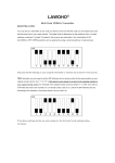
Frequently Answers and Questions
What is the maximum weight that the TWIST200E can handle?
Does the TWIST200E have a built-in pedestrian mode?
Is the TWIST200E easy to install?
Is the TWIST200E weather-resistant?
What is the warranty on the TWIST200E?
advertisement