advertisement

HP StorageWorks
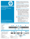
1/8 G2 Tape Autoloader
Getting started
For more detailed installation and operation instructions, see the HP StorageWorks 1/8 G2
Autoloader User and Service Guide on the CD in the Documentation Kit.
Front panel overview
1 Power button
2 Mailslot
3 LEDs
4 LCD screen
5 Control keys
6 Air vents
7 Magazines
7 2
6
1
Back panel overview
1 68-pin HD SCSI connectors
(parallel SCSI tape drive)
2 SAS port (SAS tape drive)
3 Fan
4 Power connector
5 Tape drive
6 Magazine release hole
7 Ethernet port
8 Serial port (HP Factory use only)
4 11 3 5
6
9 USB port
10 Pull-out tab containing product information
11Shipping lock storage location
1
IMPORTANT!
The shipping lock protects the robotics during shipping but must be removed for the Autoloader to work. The LCD screen displays a robot move error if the shipping lock is not removed.
IMPORTANT!
Both of the Autoloader’s side edges must be supported for the Autoloader to work properly. If you are not mounting the Autoloader in a rack or installing a desktop conversion kit, ensure that the feet are properly installed and that all of the feet are standing on a sturdy, level surface.
WARNING!
The HP StorageWorks 1/8 G2 Tape
Autoloader weighs 11.5 kg (25.4 lb.) without media and 13.1 kg (28.9 lb.) with media (8 cartridges).
When moving the Autoloader, to reduce the risk of personal injury or damage to the Autoloader:
•Observe local health and safety requirements and guidelines for manual material handling.
•Remove all tapes to reduce the overall weight of the Autoloader.
•Obtain adequate assistance to lift and stabilize the Autoloader during installation or removal.
WARNING!
When placing the Tape Autoloader into a rack, to reduce the risk of personal injury or damage to equipment:
•Extend the rack’s leveling jacks to the floor.
•Ensure that the full weight of the rack rests on the leveling jacks.
•Install stabilizing feet on the rack.
•Extend only one rack component at a time.
Racks may become unstable if more than one unit is extended at a time.
3
4
5
2
3
6
10 6
7
7 8 9
1
Choosing a location
To mount the Autoloader in a rack, select an open rack location with access to the host server and a power outlet. If possible, install the Autoloader in the middle or higher part of the rack to avoid dust from the floor.
To set the Autoloader on a table, select a level area large enough to support both side edges of the
Autoloader, with access to the host computer and a power outlet.
Place the Autoloader in an area with few sources of particulate contamination. Avoid areas near frequently used doors and walkways, stacks of supplies that collect dust, printers, and smoke-filled rooms.
Do not place the Autoloader on the floor or other carpeted surface.
Do not place the Autoloader on its sides or upside down, or stack items on top of it.
2
Unpacking the Autoloader
Remove the packaging, accessories, and Autoloader from the box one layer at a time.
Place the Autoloader on a level work surface.
Carefully remove the foam padding and then the bag from the Autoloader.
Save the packaging materials to move or ship the
Autoloader in the future.
3
Identifying product components
1
Optional rack kit
If you want to mount the Autoloader in a rack, you will need the optional rack kit.
Verify that the rack kit contains:
• 2 rack rails
• 2 packets with 8 M6 screws each
2
3 4
5
6 7
Confirm that you received the following:
1 Autoloader 5 Ethernet cable
2 SCSI or SAS interface cable
6 Six plastic feet
7 HP OpenView Storage
3 SCSI terminator (SCSI
Autoloaders only)
4 Documentation kit
Data Protector Express
Single Server Edition
CD
Optional tabletop converson kit
With the tabletop conversion kit you can place items up to 15 kg (33 lb.) on top of the Autoloader. Without the protective cover you cannot place any weight on the
Autoloader.
4
Attaching the feet
6
Installing the optional tabletop conversion kit
Skip this step if you are mounting the Autoloader in a rack or installing the optional tabletop conversion cover.
IMPORTANT!
The Autoloader must be supported under both of its side edges to work properly.
Gently turn the Autoloader over and set it on its back.
Locate the six inscribed foot location lines.
Peel the backing paper off each foot and apply it within a set of foot location lines.
Turn the Autoloader right side up.
5
Removing and storing the shipping lock
Skip this step if you do not have the optional tabletop conversion kit.
Place the cover on the work surface behind the
Autoloader. Slide the Autoloader into the cover until the front panel of the Autoloader is aligned with the cover.
Tighten the two captive screws on the Autoloader front panel until the cover is secure.
Slide the magazines into the Autoloader.
Skip Step 7 and continue with Step 8.
7a
Determining your rack type
If you are not mounting the Autoloader in a rack, skip to Step 8.
You will need a #2 and #3 Phillips screwdriver, the two rack rails, and the packet of M6 screws appropriate for your rack.
• The HP System/E rack has 7.1 mm round holes in the rack column. Choose the packet labeled HP Rack
System/E.
• The HP 5000 and 10000 racks have 9.5 mm square holes in the rack column. Choose the packet labeled
HP Rack 5000, 10000.
IMPORTANT!
The shipping lock must be removed for the robotics to work properly. A robot move error is displayed if the shipping lock is not removed.
Locate the tape holding the lock at the top of the
Autoloader. Remove the tape, then remove the lock and store it as shown.
7b
Using the screws for your rack type and a #3 Phillips screwdriver, secure the front and the back of each rail to the rack. The front of the front of the rail is flat and the back is angled, as shown.
7c
Installing the Autoloader
1
Securing the rails to the rack
2
3
Slide the Autoloader onto the rails. Secure the front bezel to the rack using a #2 Phillips screwdriver placed through the small holes in the mounting bracket to tighten the captive screws on each side of the Autoloader.
8
Preparing the host
If necessary, install software, a host bus adapter (HBA), and compatible drivers in the host computer.
Ensure that your HBA supports multiple LUNs. For parallel SCSI devices, verify that multiple LUN support is enabled for the HBA and operating system.
Check the EBS matrix at http://www.hp.com/support/ebs to verify that your HBA is supported on your host computer and qualified with the Library.
Install the HP Library & Tape Tools diagnostic utility available from http://www.hp.com/support/TapeTools to see what SCSI devices are connected to the host, verify the installation, upgrade firmware, and to aid in troubleshooting.
For SAS Autoloaders: To use the supplied SAS cable, the HBA must have an external SAS 4x (IB) connector.
HP recommends that the host server be powered down before attaching new devices.
9
Planning the parallel SCSI configuration
Go to Step 11b if your Autoloader has a SAS tape drive.
If the Autoloader will be the only parallel SCSI device connected to the host computer or you will put the
Autoloader on its own bus, skip to Step 11a.
If you are unfamiliar with configuring parallel SCSI devices, read the parallel SCSI configuration information in the User and Service Guide on the documentation CD.
Follow these general guidelines:
• The Autoloader has an LVDS SCSI bus. It is NOT compatible with a standard differential (Diff) or
High-Voltage Differential (HVD) SCSI bus.
• The Ultrium 920 is an Ultra320 SCSI device. Only put one Ultrium 920 device on an Ultra320 SCSI bus. Putting an Ultrium 920 tape drive on a lower performance bus will degrade its performance. Do not connect an Ultrium 920 device to an SE SCSI bus because it will seriously degrade performance.
• The Ultrium 448 and Ultrium 232 are Ultra160
SCSI devices. Up to two Ultrium 448 or 232 tape drives can be placed on an Ultra 320 bus. Only one can be placed on an Ultra 160 or Ultra 2 bus. Ultrium 448 and 232 devices are compatible with a single-ended SCSI bus, but their performance will be degraded.
• Avoid putting the Autoloader on the same parallel
SCSI bus as a disk drive or SE device.
• The Autoloader’s default SCSI ID is 4.
10
Changing the SCSI ID
If you need to change the Autoloader’s SCSI ID:
1. Attach the power cord to the Autoloader.
11b
Connecting a SAS
Autoloader
2. Power on the Autoloader by pressing the power button on the front panel.
To HBA
Attach the Mini SAS connector on the SAS cable to the tape drive. Attach the SAS 4x (IB) connector to the HBA.
12
Powering on the Autoloader
3. Check the LCD screen to make sure the Autoloader is receiving power.
Set the SCSI ID from the Operator Control Panel on the front panel:
1. Press Enter.
2. Press Next until the display shows Configuration.
Press Enter.
3. Press Next until the display shows Change Drive.
Press Enter.
4. Press Next until the display shows the new SCSI address. Press Enter.
Power off the Autoloader.
11a
Connecting a parallel
SCSI Autoloader
1. Attach one end of the parallel SCSI cable to one of the connectors on the drive. Attach the other end of the cable to the host bus adaptor (HBA), or the connector to the previous device on the bus.
2. If the Autoloader is the last or only device on the bus, attach a terminator to the remaining parallel
SCSI connector on the drive. Otherwise, attach the parallel SCSI cable from the next device on the bus.
Make sure that the last device on the bus is properly terminated.
Attach the Ethernet cable to the Autoloader and to the LAN.
Attach the power cord to the back of the Autoloader.
Plug the power cord into a properly grounded power outlet.
Power on the Autoloader by pushing the power button on the front panel. Check the LCD screen to make sure the
Autoloader is receiving power.
Power on the server and any devices you powered off earlier.
Verify the installation with the HP Library & Tape Tools.
13
Configuring the Autoloader
To configure the Autoloader from the OCP:
1. Click Enter.
2. Click Next until the display shows Configuration.
Click Enter.
3. Click Enter to change the administrator password.
4. The first number will flash. Click Next until the first number for the new password is displayed. Click
Enter to accept the number. The next number flashes.
Repeat for each number in the password.
5. Click Cancel to move up a level in the menu.
6. Click Next until the display shows Autoloader
Date/Time . Click Enter.
7. A number in the year will flash. Click Next and Prev until the correct number is displayed. Click Enter to accept the number. Repeat for each number in the date and time.
8. Click Cancel to move up a level in the menu.
9. Click Next to Configure Network Settings.
Click Enter.
10. The screen displays either DHCP Disabled or
DHCP Enabled . To accept this setting, click Next.
To change this setting, click Enter. Follow the directions on the display to configure additional network settings.
14
Labeling tape cartridges
15
Loading the tape cartridges
Use the OCP Operations > Unlock Left Magazine option to release the left magazine. Pull the magazine straight out of the front of the Autoloader.
Having a bar code label on each tape cartridge enables the Autoloader to identify the cartridge quickly and accurately, which speeds up inventory time.
Apply the bar code label to the recessed area on the face of the cartridge, next to the write-protect switch.
Only apply labels as designated.
IMPORTANT!
The misuse and misunderstanding of bar code technology can result in backup and restore failures. To ensure that your bar codes meet HP's quality standards, always purchase them from an approved supplier and never print bar code labels yourself. For more information, refer to the Bar Code Label
Requirements, Compatibility and Usage white paper available from http://www.hp.com/support .
Insert the tape cartridges into the slots. If you want to use the mailslot feature, leave the front slot of the left magazine empty.
3
2
1*
Mailslot
1
7
6
5
4
NOTE: When the mailslot is disabled, the mailslot becomes Slot 1 and all other slots are re-numbered.
Replace the magazine in the Autoloader.
Repeat for the right magazine.
Registering the Autoloader
Register your Autoloader online at http://www.register.hp.com
. HP customers who register join a select group who receives technical support updates and special HP offers.
16
Using the Operator Control
Panel (OCP)
1 2
The OCP has a power button, four LEDs, four control keys, and a 2-line by 16-character LCD screen. From the
OCP, you can monitor the Autoloader's status, configure it, and control its functions.
1 Control keys
The OCP displays a scrolling menu that lets you access information and execute commands using the control keys.
Cancel – Cancels the current option or returns to the previous menu level.
Enter – Enters a menu or selects the displayed option.
Previous – Selects the previous menu, option, or value.
Next – Selects the next menu, option, or value.
2 LED indicators
The OCP LEDs show Autoloader status.
Ready – Green when power is on, blinking with tape drive or robotics activity.
Clean – Amber when a cleaning cartridge should be used.
Attention – Amber if the Autoloader has detected a condition that requires attention.
Error – Amber if an unrecoverable tape drive or
Autoloader error occurs. See the LCD screen for the error message.
Helpful websites
For other product information, see: http://www.hp.com
http://www.hp.com/go/ebs http://www.hp.com/go/media http://www.hp.com/go/storage http://www.hp.com/support http://www.hp.com/support/TapeTools http://www.docs.hp.com
17
Using the Remote
Management Interface (RMI)
With the RMI, you can monitor the Autoloader’s status, configure it, and control most of its functions from a web browser or terminal. SNMP can only be configured with the RMI.
Login
Using the OCP, find the Autoloader’s IP address using the Network Information option. Open any HTML web browser and enter the Autoloader’s IP address.
Select the administrator account type and enter the administrator password.
NOTE: You must set the administrator password with the OCP before you can use the RMI’s administrator functions.
Status icons
The green Status OK icon indicates that the
Autoloader is fully operational and that no user interaction is required.
The blue exclamation point Status Warning icon indicates that user intervention is necessary, but that the device can still perform operations.
The red X Status Error icon indicates that user intervention is required and that the Autoloader may not be able to perform some operations.
Ordering media
To prolong the life of the
Autoloader and tape drive, use
HP storage media that is designed for your model.
To learn more about, or to purchase HP media, visit http://www.hp.com/go/storagemedia .
Ultrium 232 tape drive
HP Ultrium 200 GB data cartridge Ultrium 1
Part number: C7971A
Ultrium 448 tape drive
HP Ultrium 400 GB data cartridge Ultrium 2
Part number: C7972A
Ultrium 920 tape drive
HP Ultrium 800 GB data cartridge Ultrium 3
Part number: C7973A
HP Ultrium 800 GB WORM data cartridge Ultrium 3
Part number: C7973W
Ultrium 232, 448, and 920 tape drives
HP Ultrium universal cleaning cartridge (50 cleans)
Part number: C7978A
The Operator Control Panel menu
HOME
Unlock Mailslot
Mailslot Unlocked
Once sensors detect
Mailslot is open
<– Close Mailslot
Status/Information
Requires administrator password
Requires HP Service password
Configuration
Autoloader Behavior
Autoloader Date/Time
C onfigure Network Settings
Configure Auto Cleaning
Restore Defaults
Operations
Inventory Change Admin Password Unlock Left Magazines
Autoloader Information Set Reserved Slot Count Unlock Right Magazines
Drive Information Clean Drive
Component Status
Network Information
Configure Mailslot
Barcode Format
Reporting
Change Drive SCSI ID
Move Tape
Perform Inventory
Reboot Autoloader
Enable Autoloader
Password Locks
S u pport
Power On/Off Drive
Run Demo
Run Slot To Slot Test
Run Wellness Test
Upgrade Firmware
Force Drive To Eject Tape
Autoloader Error Log
Autoloader Warning Log
Download Support Ticket
HP Service Area
Printed on at least 50% total recycled fiber with at least 10% post-consumer paper
© Copyright 2007 Hewlett-Packard Development Company, L.P.
Second edition (March 2007)
Printed in the US.
www.hp.com
HP technical support
Telephone numbers for worldwide technical support are listed on the HP support website: http://www.hp.com/support.
Collect the following information before calling:
• Technical support registration number (if applicable)
• Product serial numbers
• Product model names and numbers
• Applicable error messages
• Operating system type and revision level
• Detailed, specific questions
For continuous quality improvement, calls may be monitored or recorded.
HP strongly recommends that customers sign up online using the Subscriber’s choice website http://www.hp.com/go/e-updates .
Subscribing to this service provides you with e-mail updates on the latest product enhancements, newest versions of drivers, and firmware documentation updates, as well as instant access to numerous other product resources.
After signing up, you can quickly locate your products by selecting Business support and then Storage under
Product Category.
Part no. AH163-96009
*AH163-96009*
AH163-96009
advertisement
* Your assessment is very important for improving the workof artificial intelligence, which forms the content of this project
Related manuals
advertisement