advertisement

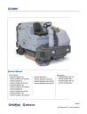
SC8000
Service Manual
Advance Models:
• 56108110 SC8000 48 LPG
• 56108111 SC8000 48 LPG ECOFLEX
• 56108112 SC8000 48 D
• 56108113 SC8000 48 D ECOFLEX
• 56108114 SC8000 60 LPG
• 56108115 SC8000 60 LPG ECOFLEX
• 56108116 SC8000 60 D
• 56108117 SC8000 60 D ECOFLEX
• 56108118 SC8000 62 LPG
• 56108119 SC8000 62 LPG ECOFLEX
• 56108120 SC8000 62 D
• 56108121 SC8000 62 D ECOFLEX
• 56108122 SC8000 48 LPG ECOFLEX
• 56108123 SC8000 62 LPG ECOFLEX
Nilfisk Models:
• 56108124 SC8000 1300 LPG
• 56108125 SC8000 1300 D
• 56108126 SC8000 1600 LPG
• 56108127 SC8000 1600 D
English
05/13 Revised 12/17 Form No. 56043167
Service Manual – SC8000 Contents ii
Contents
Service Manual Purpose and Application 8
Other Reference Manuals and Information Sources 8
Nilfisk-Advance Publications 8
Engine Manufacturers’ Technical Manuals 9
Diagnostic and Service Tools 9
Cautions and Warning Symbols 12
General Safety Instructions 12
General Machine Dimensions and Capacities 16
Engine and Machine Performance 18
Fastener Torque Specifications 18
Recommended Service Materials 19
Maintenance Every 15 to 20 Hours 20
Maintenance Every 150 Hours 20
Maintenance Every 400 Hours 21
Maintenance Every 800 to 1000 Hours 21
Maintenance Every 2000 Hours 21
Liquid Crystal Display (LCD) 32
Attention and Warning Displays 32
Control System Wiring Diagram 37
Service Manual – SC8000 Contents iii
Control Board (Driver Box) Connectors 39
J1 Main Control Board Connectors 39
J2 Main Control Board Connectors 40
J3 Main Control Board Connectors 41
Control Board (Driver Box) Programming Options 42
Foot Pedal Neutral Position and Deadband Adjustment 42
Operator Presence Control (OPC) 52
Main Control Board Fault Codes 53
Connector Callout – Relay PCB 63
Shop Measurements - Driver Box 70
Shop Measurements - Relay PCB 77
Wiring Diagram - 56108185 Rev. A Sheet 1 Kubota LPG Engine 78
Wiring Diagram - 56108185 Rev. A Sheet 2 Kubota Diesel Engine 79
Wiring Diagram Kubota 1.6L LPG Engine 56107659 REV. A 80
Wiring Harness Schematic, Machine - 56108186 REV A Sheet 1 of 2 81
Wiring Harness Schematic, Engine Interface and Kubota Diesel - 56108186 REV A Sheet 2 of 2 82
Diesel Engine Starter Circuit Diagram 83
Maintenance and Adjustments 86
Engine Air Filter Maintenance 88
Engine Overheating Problems 88
Loss of Oil Pressure Protection 89
Engine Will Not Crank - Start Inhibit Active 89
Service Manual – SC8000 Contents iv
Engine Stops Running - Run InhibitActive 89
Diesel Engine Will Not Run at High Speed or Turbo Speed 90
Troubleshooting the Kubota Engine Speed Governing System 91
Connector Callout – Relay PCB 93
Kubota 1 6L LPG Fuel System Description 94
Engine Start and Run Circuit Description 95
Engine Protection – Low Oil Pressure Shutdown 96
Engine Protection – High Temperature 96
Maintenance and Adjustments 100
Engine Air Filter Maintenance 103
Engine Overheating Problems 104
Electrical Circuit Description 109
Hydraulic Valve Block/Manifold 113
Hydraulic Manifold Assembly Component Location Key 116
Maintenance and Adjustments 117
General Information Regarding Checking Hydraulic Pressures 118
Test Port Nominal Pressure Readings 118
Service Manual – SC8000 Contents v
Recovery System Wiring Diagram 130
Electrical Circuit Description 131
Recovery System Hydraulic Diagram 131
Cylindrical Scrub System Wiring Diagram 138
Cylindrical Scrub System Hydraulic Diagrams 140
Scrub Deck Leveling Adjustment 144
Main Scrub Deck and Right Side Scrub Down 147
Main Scrub Deck and Right Side Scrub Pressure 148
Main Scrub and Side Sweep/Scrub On 149
Right Side Scrub System Wiring Diagram 152
Right Side Scrub System Hydraulic Diagrams 153
Maintenance and Adjustments 157
Side Brush Tilt Adjustment 157
Main Scrub Deck and Right Side Scrub Down 159
Main Scrub and Side Sweep/Scrub On 160
Service Manual – SC8000 Contents vi
Solution System Wiring Diagram 166
Maintenance and Adjustments 175
To Clean the Solution Filter Screen 175
To Clean the Extended Scrub System Strainer 176
To Clean the Solution Delivery Trough 176
To Clean the DustGuard™ Spray Nozzles 176
To Adjust the DustGuard™ Spray Nozzles 176
Detergent System Maintenance 177
Main and Right Side Solution Valves and Solution Pump 183
Solution and Detergent Delivery Rates 185
Squeegee System Wiring Diagram 186
Squeegee System Hydraulic Diagrams 187
Vacuum Fan On and Squeegee Down 191
Vacuum Fan Off and Squeegee Up 192
Service Manual – SC8000 Contents vii
Side Broom Sweep System Wiring Diagram 199
Side Broom Sweep System Hydraulic Diagrams 200
Maintenance and Adjustments 204
To Adjust the Side Broom Lift Actuator Motor 204
Main Scrub and Side Sweep/Scrub On 207
Wheel System, Non-traction 209
Maintenance and Adjustments 210
Foot Pedal, Hydroback and Rotary Sensor 212
Electrical Circuit Description 214
Piston Pump, Hydroback and Rotary Sensor 216
Maintenance and Adjustments 217
Foot Pedal/Hydroback Neutral Adjustment 217
Foot Pedal Neutral Deadband Adjustment 218
Push/Pull Control Cable Replacement 220
Traction Drive Motor Hose Routing 223
Wheel Drive System Torque Specifications 225
Service Manual – SC8000
General Information
General Machine Description
The SC8000 is an industrial automatic rider sweeper/scrubbers with multiple sweep/scrub single pass coverage. All models use dual cylindrical scrub brushes with variable scrub pressure and solution flow rates.
Different models are available with front mounted side brooms (single and dual) and right side disc scrub.
8
Service Manual Purpose and Application
This Service Manual a technical resource designed to aid service personnel in maintaining and repairing the
SC8000 Sweeper/Scrubbers to ensure optimum performance and long service life. Please read it thoroughly before servicing your machine.
Revision History
Revision Date
8/14
12/17
Description
• Electrical System – Wiring Diagram - 56108185 Rev. A Sheet 2, right side of image was cut off. Repaired image to show the complete diagram
• Engine System, LPG – Clarified engine speeds and control. Added part number for
Kubota engine software CD. Clarified engine oil and filter maintenance intervals.
• Engine System, Diesel – Corrected wire colors in engine speed table. Clarified engine oil and filter maintenance intervals.
• Updated hydraulic specification table
• Updated Kabuta wiring diagram
• Added procedure for leveling the scrub deck
Other Reference Manuals and Information Sources
Nilfisk-Advance Publications
Advance SC8000
• Part List - PL56042606
• Operator’s Manuals:
– OM56091075 (English, Spanish, Portuguese-Brazilian, French)
Nilfisk SC8000
• PL56042607
• Operator’s Manuals:
– OM56091076 (Danish, Norwegian, Swedish, Finnish
– OM56091077 (German, French, Dutch, Russian)
– OM56091078 (Spanish, Portuguese-Portugal, Italian, Greek)
Service Manual – SC8000
– OM56091079 (Estonian, Latvian, Lithuanian, Slovenian)
– OM56091080 (Slovakian, Czech, Polish, Hungarian)
– OM56091081 (English, Turkish, Bulgarian, Romanian)
General Information 9
These manuals can be found on the following Nilfisk-Advance’s electronic supported databases:
• Nilfisk-Advance Dealer Customer Zone
• Advance website: www.advance-us.com
• Nilfisk website: www.nilfisk.com
• EzParts service/parts CD-ROM
Engine Manufacturers’ Technical Manuals
Engine Type Manual Name
LPG
Diesel
Operator’s Manual WG1605 EG523-89162ENG.pdf
Engine Specifications WG1605 9Y110-01770.pdf
Workshop Manual WG1605 9Y111-06610.pdf
Diagnosis Manual ECM System WG1605 9Y110-01760.pdf
Kubota V1505TE Diesel Engine Operator Manual (English, French, German,
Italian, Spanish) - 16622-8916-3
Kubota V1505TE Diesel Engine Service Manual (English, French, German) -
97897-01640
Kubota V1505TE Diesel Engine Service Manual (English) - 97897-02432
Diagnostic and Service Tools
In addition to a full set of metric and standard tools, the following items are required in order to successfully and quickly perform troubleshooting and repair of Nilfisk-Advance Industrial floor cleaning equipment.
• Laptop computer loaded with current version of EzParts, Adobe Reader and (preferably cellular) internet access
• Digital voltmeter (DVM) with DC current clamp
• Hydrometer
• Battery load tester for checking 6V and 12V batteries
• Automotive fuel pressure test gauge.
• Static control wrist strap
• Set of torque wrenches
• Hard (printed) copies of service manuals for regularly serviced machines (available at www.advance-us.com
, www.nilfisk.com
and other Nilfisk-Advance websites)
Service Manual – SC8000
These tools are also available from Nilfisk-Advance, Inc.:
• Vacuum water lift gauge, p/n 56205281.
• Engine service kit, p/n 56109084, includes an LPG Test
Kit, p/n 56504450, and a Diagnostic Communication
Cable and software, p/n 56305647 (Used on other model GM Engines as well as Kubota LPG in the
SC8000. Kubota engine requires updated GCP display software.
General Information 10
Engine service kit, p/n 56109084
LPG test kit, p/n 56504450
• Hydraulic test gauge w/connector, 3000 psi range, p/n
56504516
ECOM Diagnostic Communication Cable and software, p/n 56305647
Hydraulic test gauge w/connector
3000 psi range, p/n 56504516
Service Manual – SC8000 General Information 11
Conventions
All references to right, left, front and rear in this manual are as seen from the Operator’s seat position.
Parts and Service
Repairs should be performed by an Authorized Nilfisk-Advance Service Center that employs factory-trained service personnel and maintains an inventory of Nilfisk-Advance original replacement parts and accessories.
Call the Nilfisk-Advance Dealer named below for repair parts or service. Please specify the Model Number
(same as the Part Number) and Serial Number when discussing your machine.
(Dealer, affix service sticker here.)
Nameplates
The Model Number and Serial Number of the machine are shown on the
Nameplate
located on the steering column support, and on a second
Nameplate
beneath the floor plate attached to steering spindle support.
This information is needed when ordering repair parts for the machine.
Nameplate
Nameplate
Service Manual – SC8000 General Information 12
Cautions and Warning Symbols
Nilfisk-Advance uses the symbols below to signal potentially dangerous conditions. Read this information carefully and take the necessary steps to protect personnel and property.
Danger! Is used to warn of immediate hazards that will cause severe personal injury or death.
Warning! Is used to call attention to a situation that could cause severe personal injury.
Caution! Is used to call attention to a situation that could cause minor personal injury or damage to the machine or other property.
Read all instructions before using.
General Safety Instructions
Warning! Be sure to follow these safety precautions to avoid situations that could cause severe personal injury.
• This machine should only be used by properly-trained and authorized persons.
• While on ramps or inclines, avoid sudden stops when loaded. Avoid abrupt sharp turns. Use low speed down hills. Clean only while ascending (driving up) the ramp.
• Keep sparks, flame and smoking materials away from the battery. Explosive gases are vented during normal operation.
• Charging the battery produces highly-explosive hydrogen gas. Charge the battery only in wellventilated areas away from open flame. Do not smoke while charging the battery.
• Remove all jewelry when working near electrical components.
• Turn the Key Switch off (O) and disconnect the battery before servicing electrical components.
• Never work underneath a machine without safety blocks or stands to support the machine.
• Do not dispense flammable cleaning agents, operate the machine on or near these agents, or operate in areas where flammable liquids exist.
• To avoid hydraulic oil injection or injury, always wear appropriate clothing and eye protection when working with or near any hydraulic system.
• The maximum rated incline for sweeping and scrubbing is 10.5% (6°). The maximum rated incline during transport is 16% (9°).
• Only use the brushes provided with the machine or those specified in the instruction manual.
The use of other brushes may impair safety.
Service Manual – SC8000 General Information 13
Caution! Do not pressure-wash the operator control panel, electrical components or the engine compartment area.
Caution! Be sure to follow these safety precautions to avoid situations that could cause personal injury, damage to property or equipment damage.
• This machine is not approved for use on public paths or roads.
• This machine is not suitable for picking up hazardous dust or fluids.
• Use care when using scarifier discs and grinding stones. Nilfisk-Advance will not be held responsible for any damage to floor surfaces caused by scarifiers or grinding stones.
• When operating this machine, make sure that bystanders, particularly children, are not endangered.
• Before performing any service function, carefully read all instructions pertaining to that function.
• Do not leave the machine unattended without first turning the Key Switch off (O), removing the key and securing the machine.
• Apply the parking brake before exiting the Operator’s seat.
• Turn the Key Switch off (O) and remove the key before changing the brushes, and before opening any access panels.
• Take precautions to prevent hair, jewelry or loose clothing from becoming caught in moving parts.
• Use caution when steering and/or operating this machine in below-freezing temperature conditions. Any water in the solution or recovery tanks, or in the hose lines could freeze, causing damage to valves and fittings. Flush with windshield washer fluid.
• The battery must be removed from the machine before the machine is scrapped. Disposal of the battery should be done safely and in accordance with your local environmental regulations.
• Do not use on surfaces having a gradient exceeding that marked on the machine.
• All doors and covers are to be positioned as indicated in the instruction manual before using the machine.
Service Manual – SC8000 General Information 14
Jacking the Machine
Warning! Never work under a machine without safety stands or blocks to support the machine.
When jacking the machine, do so at the designated Tie Down/Jacking Locations shown below.
Transporting the Machine
Caution! Before transporting the machine on an open truck or trailer, make sure the machine is tied down securely at the designated Tie Down/Jacking Locations shown below, all access doors and covers are secured (tape and strap as needed) and the parking brake is engaged.
The jacking and tie down locations are identified with a graphic molded into the exterior body panels.
Tie Down/Jacking
Location
Tie Down/Jacking
Location
Service Manual – SC8000 General Information 15
Towing the Machine
Caution! The machine’s hydrostatic drive propulsion system pump is manufactured with a tow valve. This valve allows the hydraulic traction drive motor to “freewheel” when the machine is being towed/pushed short distances without the use of the engine.
The tow valve is controlled by the Tow Valve Lever which is accessed by opening and propping up the Engine Cover. Pull the Tow Valve Lever OUT to engage the fluid bypass and allow the drive motor to freewheel before towing the machine.
Note that if the tow valve is left in the freewheeling position (Tow Valve Lever pulled
OUT), the hydrostatic pump can’t efficiently propel the machine in forward or reverse.
Attempting to operate the machine with the Tow Valve Lever pulled OUT can cause overheating of the hydraulic system and/or reduced operating performance.
Tow the machine no faster than a normal walking pace (2-3 miles per hour/
3-5 kilometers per hour), and for no farther than 300 feet [100 meters]. Towing or pushing the machine farther than 300 feet [100 meters] can cause machine damage.
If the machine is to be moved farther than 300 feet [100 meters], raise the front drive wheel off the floor and place on a suitable transport dolly.
Engine
Cover
Tow Valve
Lever
Service Manual – SC8000 General Information 16
Technical Specifications
General Machine Dimensions and Capacities
Length
Height
Height (with overhead guard)
Width/frame (roller to roller)
100 in [254 cm]
58 in [147 cm]
84 in [213 cm]
56 in [142 cm]
Width (with rear squeegee)
Width (with right side scrub brush)
57 in [144.7 cm]
66 in [167.6 cm]
Cleaning path width (main brush only) 48 in [121.9 cm] deck size all models
Cleaning path width (with right side scrub brush ) 60 in [152.4 cm]
Cleaning path width (dual sweep)
Main brush diameter and length
Side scrub brush (right)
Side broom sweep
Solution tank capacity (3 inches from top)
Recovery tank (shutoff)
Scrub brush pressure (three settings)
Main brush RPM
Debris hopper volume capacity
Debris hopper weight capacity
Weight empty
Weight GVWR
Minimum aisle turn
Transport ground clearance
Operator sound level @ operator ear
Vibration level @ steering wheel
Certification
62 in [157.4 cm]
11 in x 48 in [27.9 cm x 121.9 cm]
16 in [40.6 cm]
20 in [50.8 cm]
100 gal. [378L]
100 gal. [378L]
(1) 150 lbs
1.5 ft
3
[.04 m
3
]
150 lbs [68 Kg]
119 in [302 cm]
(2) 250 lbs
400 RPM @2200 engine RPM
2975 lbs [1349 Kg]
4135 lbs [1875 Kg]
(3) 400 lbs
3 inches [7.62 cm] when in transport
82.4 dBA @ 2200 RPM does not exceed 0.80 m/s
ETL
Service Manual – SC8000
Overall Dimensions
General Information 17
Service Manual – SC8000
Engine and Machine Performance
4-cylinder 1.6L WG1605 Kubota
LPG
Engine speeds
4-cylinder 1505 Kubota Diesel
Transport speed forward
Transport speed reverse
Grade ability – Cleaning
Grade ability – Transporting
Idle - 1200 RPM
Normal Run - 2200 RPM
High Output Turbo - 2400 RPM
Idle - 1300 RPM
Normal Run - 2200 RPM
High Output Turbo - 2400 RPM
8 mph [12.8 kph]
3 mph [4.8 kph]
6° / 10.5% - all models
9° / 16% - all models
Fastener Torque Specifications
Standard Torque
Specifications
(unless otherwise specified)
Size
#10
1/4“
5/16”
3/8”
1/2”
3/4”
M5
M6
M8
M10
M12
Plated Steel
42 in.-lb.
100 in.-lb.
17 ft.-lb.
31 ft.-lb.
75 ft.-lb.
270 ft.-lb.
61 in.-lb.
9 ft.-lb.
22 ft.-lb.
44 ft.-lb.
70 ft.-lb.
Stainless Steel
28 in.-lb.
67 in.-lb.
11 ft.-lb.
20 ft.-lb.
50 ft.-lb.
180 ft.-lb.
36 in.-lb.
62 in.-lb.
13 ft.-lb.
25 ft.-lb.
40 ft.-lb.
General Information 18
Maintenance
Maintenance Schedule
Keep the machine in top condition by closely following the maintenance schedule. Maintenance intervals given are for average operating conditions. Machines used in severe environments may require service more often. In general:
• Keep the fuel tank filled (diesel). This helps to reduce condensation and moisture entering the fuel system.
• Be aware of the yellow Attention Indicator light, the red Warning Indicator light and the liquid crystal display (LCD) on the Operator panel for icons and fault codes that indicate a critical or non-critical fault condition. Refer to the
Liquid Crystal Display (LCD)
section for a listing and explanation of the LCD icons and fault codes.
• Refer to the engine service manual for recommended engine service intervals and procedures.
Service Manual – SC8000
Recommended Service Materials
• Engine Oil (refer to your engine manual)
• Hydraulic oil (10W-30)
• Manufacturer-recommended coolant (antifreeze) 50/50 mix
• Lithium-base grease
• Loctite
®
(or equivalent) thread sealant in the appropriate grades
• Never-Seez
®
(or equivalent) anti-seize compound
General Information 19
Daily Maintenance
Caution! Do not pressure-wash the operator control panel, electrical components or engine compartment area.
Maintenance Item
Perform “After Use” maintenance steps
Engine
Operator control panel
Hydraulic system
Recovery tank
Squeegee pick-up tool
Scrub housing side skirts
Scrub brushes, main and right side
Main and side brooms
Wet debris hopper
Parking brake and foot pedal brake
Procedure
“After use” maintenance is normally the responsibility of the machine Operator. Refer to the Instructions for Use.
Check the engine oil level.
Check the engine coolant level in the reservoir.
Check for engine and coolant leaks.
Check the air cleaner service indicator and service the air filter when the indictor is shown red.
Check for a hydraulic filter plugged icon on the operator panel display.
Check the oil level in the hydraulic oil reservoir (level should be to bottom of screen).
Check for any hydraulic leaks.
Check that the drain hose cap is sealed.
Drain and clean the inside of the tank; flush with clean water.
Check the cover gasket for damage/wear.
Clean the squeegee tool; check the blades for damage/wear and deflection.
Check for damage/wear.
Check for debris wrapped around the brushes/brooms and for damage/wear.
Clean the hopper, debris screen and hose.
Check for correct operation of brakes; adjust as needed.
Service Manual – SC8000
Maintenance Every 15 to 20 Hours
Maintenance Item
Battery
Solution tank filter
EcoFlex
™
detergent systems
Scrub deck skid plates
Scrub brushes
DustGuard
™
General Information 20
Procedure
Check the electrolyte level in the battery.
Check the battery cables and connections.
Inspect and clean the debris filter on the solution filter system.
Purge the detergent delivery lines.
Inspect for wear (replace if worn to ¼ inch)
Rotate and flip the main scrub brushes.
Clean the dust control system spray nozzles.
Monthly Maintenance
Maintenance Item
Squeegee caster wheel axle and pivot
Steering Rack
Angle adjustment knob threads on the squeegee mount
Squeegee tool end wheels
Fuel Tank Cover Latch
EcoFlex
™
/ AXP
™
Cover Latch
Recovery tank latch
Brake Pedal (parking brake) linkage
Procedure
Pump a small amount of grease into each grease fitting on the machine until grease seeps out around the bearings.
Apply grease to lubricate.
Apply light machine oil to lubricate.
Maintenance Every 150 Hours
Maintenance Item
Engine maintenance
Radiator and oil cooler
Steering
LP fuel system electronic pressure regulator (EPR) – LP engines only
Procedure
Change the engine oil and oil filter. *Also review the engine manufacturer’s additional maintenance requirements.
Inspect and clean the exterior core cooling fins.
Inspect and apply grease to the spur gear and rack.
Inspect and drain any oil buildup from the LP fuel system EPR.
Service Manual – SC8000
Maintenance Every 400 Hours
Maintenance Item
Air intake housing and hoses
Hydraulic hoses
Battery
Fuel Filter
General Information 21
Procedure
Inspect the complete air intake system for correct routing, kinks, restrictions, sound tight connections, holes and cracks in hoses.
Inspect for leaks, wear, cracking and kinks.
Check electrolyte level; check terminals for corrosion, loose connections.
Replace fuel filter cartridge (located before injector pump).
Replace the fuel filter at the electronic fuel pump.
Maintenance Every 800 to 1000 Hours
Maintenance Item
Radiator
Hydraulic oil reservoir
Procedure
Flush and refill radiator with 50/50 mix of water and antifreeze.
Change the reservoir oil and filter.
Maintenance Every 2000 Hours
Maintenance Item
Engine maintenance (LPG and diesel only)
Procedure
* Review the engine manufacturer’s additional maintenance requirements.
*Note: The engine maintenance schedule shown lists the recommended engine service intervals.
Refer to the
Other Reference Manuals and Information Sources
/
Engine Manufacturers’
Technical Manuals
section for list of available engine manufacturers’ service manuals. Refer to these manuals for more complete maintenance and service information and instructions.
Service Manual – SC8000
Lubrication Points
Brake Pedal
(parking brake)
Linkage (oil)
Steering
Rack (grease)
Fuel Tank
Cover
Latch (oil)
Detergent
Cover Latch
(oil)
General Information 22
Squeegee
End Tool
Wheel (oil)
Recovery
Tank Latch
(oil)
Squeegee
End Tool
Wheel (oil)
Squeegee
Caster Wheel
Pivot (grease)
Squeegee
Caster
Wheel Axle
(grease)
Angle
Adjustment
Knob Threads on Squeegee
Mount (grease)
8
9
10
11
12
13
14
15
16
17
18
19
20
21
22
23
1
2
3
4
5
6
7
Ref
PM Check List - SC8000
Customer________________________________________________________
Address__________________________________________________________
Ciry_________________________ St________________ Zip______________
Operational Inspection Items
Check drive pedal sensor operation (to test depress drive pedal and start the engine, it should not start.)
Engine starting with pedal in neutral (if it will not start check pedal calibration programming)
Engine idle speed, LPG/1200 RPM and Diesel/1300 RPM
Normal operational speed (run switch setting) 2200 RPM
Turbo high-speed (hold 2200 RPM switch setting for 2 sec. to enter )
2400 RPM
Drive pedal linkage (check for Fwd/Rev drive and any neutral creep)
Drive system performance (max Fwd 8 mph)
Brakes
Steering
Right side scrub brush raise/lower (model option if equipped)
Right side scrub brush on/off (must have main scrub turned on)
Side sweep broom(s) raise/lower (model option if equipped)
Side broom(s) on/off
Dust guard (sweep dust control) On/Off (model option if equipped)
Scrub system (Raise/Lower and auto scrubbing functions)
Main scrub brushes On/Off (will drift)
Scrub Brush (pressure settings 1, 2 and 3)
Solution control (On/Off and flow volume min/max)
Test and purge the detergent EcoFlex™ / AXP™ system (if so equipped)
Squeegee system (raise/lower and auto lift in reverse)
Vacuum Performance (Sealed water lift 34” @ 2200 RPM)
Headlights, gauges and (optional) accessories rotating beacon, backup alarm
Tilt steering mechanism and seat adjustment lever
Defect Codes
A Needs Adjustment
B Binding
C Contaminated or dirty
D Damaged, bent or torn
L Leaks
M Missing
W Worn out
OK Defect Codes
(Circle)
A B C
A
A rough
A low power
A B
Noisy sluggish
A B W excessive play
B D L
B L
A B
B L
A C L
A B
C D
C L W
C L
Does
Not
Work
59
60
53
54
55
56
57
58
49
50
51
52
45
46
47
48
28
29
30
31
32
33
34
35
36
37
24
25
26
27
38
39
40
41
42
43
44
Ref Visual Inspection Items Comments
Side sweep broom(s) bristles
Side broom motor(s)
Scrub brush motor(s)
Main scrub brushes, check for wear and rotate (1.75” length) min wear 3 inches
Right scrub brush
Min wear .875 inches
Scrub deck housing and door skirts
Solution system pumps and solenoid valves as many as four pumps
Solution tank, delivery hoses and filter
Vacuum impeller motor and hose
Recovery tank screen and float clean filter screen clean screen
Recovery tank cover gasket
Recovery tank drain hose and cap
Squeegee pick-up hose
Squeegee tool and blades
Squeegee casters, leveler adjustment knob and linkage
Hydraulic lift cylinders (squeegee, right side and main scrub deck) back flush clean and rotate grease
Battery
Engine, oil level, hoses and belts clean and water
Engine air cleaner element (inner and outer) check service indicator
Engine coolant level fill at reservoir
Radiator and oil cooler core blockage
Hydraulic oil reservoir level (10W-30 engine oil only)
Hydraulic system hoses and fittings
Propulsion (drive) pump dump valve (tow valve)
Propulsion drive and accessory pump clean to bottom of screen
Propulsion pump hydroback cable and clevis connections
Propulsion pump hydraulic filter
Diesel fuel tank, filter and lines
LP tank, hoses and fittings
LP fuel filter
LP fuel regulator, lock-off valve and hoses
Diesel glow plug function light
Diesel fuel tank strainer
Brake cable
Circuit breaker panel
Front tire (check lug nut torque 100 ftlbs/135Nm)
Front drive wheel motor, steer spindle, rack and cylinder
Front and rear tires service life 1500 Hrs hard starting yearly grease pinion and rack tread wear
OK Defect Codes Does
Not
Work
A B D W
B L
B L
D W
C D W
C D W
C L M
C L D
B C
D L W
C D L M
C L
C D W
C W
B L
C
C D L
C L
C L
C D L
C L
L
B D
L
A B D
C L
C L W
L W
C
L
C
D M W
A
D L W
C W
Service Manual – SC8000
Ref Visual Inspection Items Comments
61
62
63
Scrub housing debris hopper (tray)
Scrub housing recovery hose and pick-up screen
Dust guard spray nozzles and strainers clean back flush/clean clean
Defect Codes A needs adjustment C dirty or contaminated M missing
B binding D damaged, bent or torn W worn out
L leaks
General Information 25
OK Defect Codes Does
Not
Work
C
C
C L W
Work Completed by: Acknowledged by:
____________________________________ __________ ____________________________________ ___________
Service Technician Signature Date Customer Signature Date
Service Manual – SC8000
General Machine Overview
Major Machine Components
General Information 26
Operator
Seat
Adjustment
Lever
Steering
Wheel
Operator
Seat
Solution
Tank Fill
Cover
Recovery
Tank Tilt-out
Latch
Engine
Cover
Recovery
Tank Cover
Engine Air
Filter Service
Indicator
Fuel Tank
Cover
Latch
Recovery
Tank Tilt-out
Grip
Coolant
Overflow
Tank
Engine
Air
Filter
Recovery
Tank
Drain Hose
Engine
Cover
Latch
Left Side
Skirt Latch
Fuel Tank
Cover
Headlight
Fuel Tank
(Diesel tank shown)
Double Scrub
Skirt Holder
Left
Side Skirt
Service Manual – SC8000 General Information 27
Control
Panel
Circuit
Breaker
Panel
Brake Pedal/
Parking Brake
Steering
Wheel
Tilt Adjust
Lever
Engine Oil
Dipstick
Oil Cooler
Tilt-out Latch
Hydraulic OIl
Reservoir
Filler Cap
Engine
Oil Drain
(under radiator)
Squeegee Tilt
Adjust Knob
Engine Cover
Prop Rod
Squeegee
Mount
Wrench
Engine
Oil Filter
Squeegee
Height
Adjust
Knob
Solution
Tank Drain
Hose
Tow Valve
Lever
Battery
Solution
Filter
Hopper
Right Side
Skirt Latch
Squeegee
Assembly
Drive Pedal
Direction/
Speed
Detergent
Cartridge
Compartment
Right Side
Skirt
Right
Scrub
Skirt
Retainer
Knobs
Right Scrub
Skirt Assembly
Service Manual – SC8000 General Information 28
Control Panel Switches
•
Horn Switch
– sounds the horn when pressed.
•
Extended Scrub Switch
– enables the optional extended scrub (recycle) function.
Horn
Switch
Extended
Scrub
Switch
Detergent
Switch
•
Detergent Switch
– enables and disables the detergent system (on models so equipped).
•
Solution Flow Increase Switch
– increases the solution flow rate one level when pressed. Note that the LCD will display the solution flow rate (one to five bars).
•
Solution Switch
– enables and disables the solution system.
Vacuum/
Wand
Switch
EcoFlex™
Switch
Solution
Flow
Increase
Switch
Solution
Switch
Solution
Flow
Decrease
Switch
•
Solution Flow Decrease Switch
– decreases the solution flow rate one level when pressed.
•
EcoFlex ™ Switch
– functions as follows:
– On Machines Equipped with EcoFlex
™
:
The machine will default to the EcoFlex
™
cleaning mode (the EcoFlex
™
indicator will be on) to conserve solution and detergent. Pressing the
EcoFlex ™ Switch
temporarily overrides the EcoFlex
™
cleaning settings and does the following:
◦ Increases the scrub pressure to the next highest scrub pressure,
◦ Increases the solution flow to the next highest flow rate, and,
◦ Increases the detergent ratio to the next highest concentration.
The EcoFlex
™
indicator will blink, and the scrub pressure, solution flow and detergent concentration will remain at these higher levels for 60 seconds. After 60 seconds, the scrub pressure, solution flow and detergent concentration will return to their previous settings, and the EcoFlex
™
indicator will stop blinking.
Note: Pressing and holding the
EcoFlex
™
Switch
for two seconds enables the full concentration detergent cleaning mode. The only way to re-enable the EcoFlex
™
mode is to push the
EcoFlex
™
Switch
again. Cycling the key switch does not re-enable the system. The EcoFlex system will only function if the scrub system is enabled.
™
– On Machines Not Equipped with EcoFlex
™
, the
EcoFlex ™ Switch
is not functional.
•
Vacuum/Wand Switch
– enables and disables on the vacuum system.
Service Manual – SC8000
•
Left
and
Right Turn Signal
– (optional) switch on the corresponding turn signal.
•
LCD
(liquid crystal display) – displays the various machine status icons and informational displays.
•
Scrub On/Scrub Mode Select Switch
– enables the scrub, solution and recovery systems, and the side broom/brush system and detergent system (if the machine is so equipped). Note that the scrub brush pressure and solution flow will be at their lowest levels. The scrub brushes will run, the solution will flow and the squeegee vacuum will turn on when the machine begins moving forward.
Pressing the
Scrub On/Scrub Mode Select Switch
with the scrub system enabled will increase the scrub pressure and corresponding solution flow one step each time the switch is pressed.
•
Scrub Off Switch
– switches off the scrub, solution and recovery systems, and the detergent system (if the machine is so equipped).
General Information 29
Left Turn
Signal
LCD
Right Turn
Signal
Scrub Off
Switch
Scrub On/
Scrub Mode
Select Switch
•
Side Broom Up Adjust Switch
– raises the side broom(s).
•
Side Broom/Scrub On/
Off Switch
– enables and disables the side broom(s) and/or right side scrub system. Note that when the side broom(s)/scrub brush system is enabled, the DustGuard™ spray system will also switch on automatically. Also note that when the side broom(s)/scrub brush system is enabled, the broom(s)/brush will return to their last-used position.
•
Side Broom Down Adjust
Switch
– lowers the side broom(s).
Side
Broom
Up
Adjust
Switch
Side
Broom/
Scrub
On/Off
Switch
Side
Broom
Down
Adjust
Switch
•
Emergency Flashers
– switches on the emergency flashers (if the machine is so equipped).
•
Headlight Switch
– switches on the headlights.
Emergency
Flashers
(optional)
DustGuard™
Switch
Headlight
Switch
Engine
Speed
Switch
Key
Switch
•
DustGuard
™
Switch
– enables and disables the DustGuard
™
spray nozzles. Note that if the machine is equipped with an extended scrub system, the DustGuard
™
nozzles will shut off when the machine runs out of clean solution.
Service Manual – SC8000 General Information 30
•
Engine Speed Switch
– selects the engine speed as follows:
– Pressing the switch with the engine idling (1200 RPM – LPG, 1300 RPM – diesel) will increase the engine speed to the normal transport/scrub speed (2200 RPM).
– Pressing the switch with the engine at normal operating speed will return the engine speed to idle.
– Pressing and holding the switch for two seconds with the engine at normal operating speed will increase the engine speed to the “Turbo” speed (2400 RPM).
– Pressing the switch with the engine at “Turbo” speed will return the engine to normal operating speed
(2200 RPM).
Note: The SC800 has an automatic idle feature that will reduce the engine speed to idle when the foot pedal has been in the neutral position for 20 seconds or more. The selected engine speed will automatically resume when the foot pedal is moved from neutral. If the
Engine
Speed Switch
is pressed while in idle-override, the automatic idle feature will be temporarily disabled until the next time the foot pedal is moved from the neutral position. This can be useful during troubleshooting, or if you want to run the machine at full speed to warm it up.
•
Key Switch
– main power/ignition switch.
Control Panel Indicators
•
Extended Scrub Indicator
– indicates that the optional extended scrub system is enabled.
Extended
Scrub
Indicator
Detergent
System
Indicator
•
Detergent System Indicator
– indicates that the detergent system is enabled.
•
Solution System Indicator
– indicates that the solution system is enabled.
Solution
System
Indicator
•
EcoFlex ™ Indicator
– functions as follows:
– The indicator lights steadily during normal
EcoFlex
™
operation.
– The indicator flashes to indicate the 60-second burst of power override that increases of the scrub pressure, solution flow and detergent concentration settings.
Vacuum/
Wand
Indicator
EcoFlex ™
Indicator
– The indicator switches off when the EcoFlex
™
system is off and the machine is in the maximum concentration detergent mode.
•
Vacuum/Wand Indicator
– indicates that the vacuum system is enabled.
Service Manual – SC8000
•
Left
and
Right Turn Indicators
– indicate that the corresponding turn signal is flashing.
•
Warning Indicator
– lights in conjunction with the LCD to alert the Operator of a warning or fault condition.
•
Attention Indicator
– lights in conjunction with the LCD to alert the Operator of a machine condition requiring attention.
•
Scrub Pressure Indicators
(
1
,
2
and
3
) – indicate the current scrub pressure.
Left Turn
Indicator
Warning
Indicator
(red)
•
Side Brush/Broom Indicator
– indicates that the side broom/brush system is enabled.
•
Emergency Flasher Indicator
– indicates that the emergency flashers are switched on.
•
Headlight Indicator
– indicates that the headlights are switched on.
•
DustGuard ™ Indicator
– indicates that the
DustGuard
™
system is enabled.
•
Engine Speed Indicator
– indicates that the engine is at either normal operating speed or “Turbo” speed. The light will be off when the engine is off or at idle.
Side Broom/
Brush
Indicator
Emergency
Flasher
Indicator
Headlight
Indicator
DustGuard™
Indicator
Engine
Speed
Indicator
General Information 31
Right Turn
Indicator
Attention
Indicator
(yellow)
Scrub
Pressure
Indicators
Service Manual – SC8000
Liquid Crystal Display (LCD)
General Displays
The LCD shows the total sweep/scrub time on the hour meter, the fuel gauge, the current scrub pressure and the current solution flow rate.
If the machine is equipped with an EcoFlex
™
system, the display will also show the detergent system icon and current dilution ratio or percent.
If the machine is equipped with an extended scrub system, the display will show the extended scrub indicator when the system is enabled.
Hour
Meter
Dilution
Ratio or %
General Information 32
Fuel
Gauge
Extended
Scrub
Indicator
(optional)
Attention and Warning Displays
The driver box (main control board) will switch on the yellow attention indicator light or the red warning indicator light and display the appropriate icon to communicate specific monitored operational (modes) activities to the machine operator.
Attention Displays
Example: The main controller board shows the non-critical controller fault code icon with a two-digit code (08) and wrench symbol. This is a non-critical fault code that indicates the right side scrub solution solenoid valve is over its current limit. The right side scrub system will shut off but the rest of the machine systems will continue to operate.
Attention
Indicator
Icon
Solution Level Low
Hydraulic Filter
Plugged
Condition
The float switch in the solution tank is indicating that the solution tank is empty.
Fill the solution tank to clear the warning indicator and icon.
The hydraulic filter needs to be replaced
(serviced). Note that the oil temperature must be above 100 degrees F for a plugged filter to activate the icon. (This prevents a false indication with cold oil start-ups.)
Display Icon
Service Manual – SC8000 General Information 33
Icon
Diesel Glow Plug
Start
Controller Noncritical Fault
Recovery Tank Full
Condition
The key switch is in the run position and the glow plugs are activated (heating up) for their timed 10 seconds. The engine can be cranked to start when the yellow attention light and display icon go out.
The driver box (main control board) has sensed specific system component failure(s) and displays a two-digit number and the wrench symbol. See the
Control System/Main Control
Board Fault Codes
for a description of the fault codes and recommended troubleshooting procedures. Note that when non-critical faults exist, hour meter will be displayed in rotation with faults,
The tank float has sensed a high water level. The operator needs to empty the waste water from the tank. If tank is empty and the icon is displayed, service
(clean) the tank float (it could be stuck).
Also check the float circuit wiring for an open.
Warning Displays
Example: The main controller board shows the engine service icon with a two-digit fault code (38) and wrench symbol. This is a critical engine fault code that indicates the main control board received a run-inhibit signal from the ECM (LPG) or governor (diesel) that will shut down the engine.
Warning
Indicator
Display Icon
300:1
Icon
Parking Brake
Engaged
Diesel Oil Pressure
Condition
The parking brake is engaged. The icon and warning light will disappear when the
Operator releases the brake.
Low engine oil pressure in the diesel engine is sensed. Check for possible causes for low oil pressure such as engine crankcase level is low, incorrect oil viscosity, fault in oil pressure switch
S28, excessive engine wear or defective internal oil pump (relief valve). Note that this icon display is for the Kubota diesel engine only.
Display Icon
Service Manual – SC8000
Icon
Engine Service
Battery Low
Controller Critical
Fault
Hydraulic
Temperature
Low Fuel
Engine Coolant
Temperature
Condition
The Kubota 1.6L engines ECM
(electronic control module) has activated an engine fault code. See the
Engine
System, LPG / Engine Diagnostics
section for more detailed diagnostic help.
Low battery voltage. Check the alternator output; test the battery; clean and tighten the cables.
The main control board has sensed a specific system component failure(s) and displays a two-digit number with a wrench icon. See the
Control
System/Main Control Board Fault
Codes
section for code descriptions and recommended troubleshooting procedures. Note that some critical faults will prevent the operation of certain machine functions.
The hydraulic oil temperature has exceeded an average operating temperature greater than 220 degrees
F. for longer than 15 seconds. Possible causes include low oil level in the reservoir, debris blocking airflow at the oil cooler or hydraulic component overloads.
The fuel sensors read low fuel levels from the liquid fuel tank (diesel) or low pressure from the LP storage cylinder.
Refill the diesel tank (10-gallon capacity).
Replace the LP cylinder (33-pound liquid capacity).
High coolant temperature sensed has caused and engine fault. Check for low coolant level in the radiator, debris blocking airflow through the radiator, fan damage, loose fan belt, leaks, bad engine water pump, engine overload at high ambient temperature.
General Information 34
Display Icon
Service Manual – SC8000
Chassis System
Major Chassis Components
Front Hood
Floor
Weldment
Front
Floor Tank
Heavy
Bumper
Assembly
Chassis
Weldment
Rear Cover
Assembly
Cover
Support
Assembly
35
Service Manual – SC8000
Latch
Handle
RH
Latch
Cover
Support
Weldment
Heavy
Bumper
Weldment
Rear
Cover
Chassis System 36
Rear
Grille
Service Manual – SC8000
Control System
Functional Description
Overview
The Control System includes the Driver Box (main controller) and the Dashboard Panel. The Dashboard
Panel communicates with the Driver Box via a CAN Bus. The Driver Box controls the machine electrical and hydraulic systems by actuating the appropriate pumps and solenoid valves to perform the required scrubbing, sweeping and drive functions.
The Driver Box communicates with the Engine System controller on the Kubota LPG engine, and the APECS 3000 Governor on the Kubota diesel to monitor engine parameters. The Driver Box also communicates with the Relay PCB which provides the engine start and run signals.
Control System Wiring Diagram
37
Driver Box
J1-12
Ignition_KeyPos
3
1
F1
2
Fuse, 100A
1
2
Circuit Breaker, 15A
CB6
B
S1
Switch, Ignition
B1
J1-3 CAN +
J1-2 CAN -
Twisted Pair Twisted Pair
J1-18
J1-5
2 1
Switch, Seat
Battery
12 VDC
J6-1 (B+) J6-2 (B-)
J6-3 CAN +
J6-4 CAN -
Dashboard Panel
Circuit Description
The Key Switch must be on to provide power to the
Driver Box
and
Dashboard Panel
. The
Driver Box
and
Dashboard Panel
communicate over the CAN Bus.
Service Manual – SC8000
Component Locations
Dashboard
Panel
Main Control Board
Connector J3
Main Control Board
Connector J2
Main Control Board
Connector J1
Relay PCB
Start/Run
Inhibit
K1 Power
Relay
Driver
Box
Control System 38
Service Manual – SC8000
Control Board (Driver Box) Connectors
J1 Main Control Board Connectors
Pin# Wire#
J1-1 18-1
Color
GRA
Type
Input
Goes To
Engine control module output
J1-2 20-1 BLK/YEL -CANbus User interface panel (membrane switches)
J1-3 20-1 ORN/BLK +CANbus User interface panel (membrane switches)
J1-4
J1-5 18-3
J1-6
YEL Input
Open
Seat Switch (EcoFlex
™
only)
Open
J1-7 18-1 GRA/BLK
J1-8
J1-9
J1-10 18-1 BRN/WHT
Input
Output
Fuel level sensor for either diesel or LP
Open
Open
Foot pedal position potentiometer (sensor high)
J1-11 18-1 YEL/GRA Output
J1-12 18-1
J1-13
J1-14
J1-15
J1-16 18-1
J1-17
J1-18 16-1
J1-19 18-1
J1-20 18-1
J1-21 18-1
ORN/GRN
RED/BLK
BLK
GRN/ORN
VIO/WHT
VIO/YEL
J1-22 18-1 WHT/BRN
J1-23
J1-24 18-2 VIO/BRN
J1-25 18-1 GRN/YEL
J1-26
J1-27 18-1 GRA/YEL
J1-28
J1-29
J1-30 18-1
J1-31 18-1
J1-32 18-1
J1-33 18-1
J1-34 18-1
J1-35
VIO/BLU
ORN/GRA
RED/YEL
BRN/BLU
YEL/WHT
Input
Input ground
Input
Input
Input
Output
Input
Input
Input
Input
Input
Input
Input
Output
Foot pedal position potentiometer (sensor low)
Key switch ignition switch (run)
Open
Open
Open
S29 Horn switch
Open
Chassis ground X-49
Sender hydraulic oil temperature
S6 Brake switch
S3 Solution empty switch
Relay PCB (start inhibit pin# J7-3)
Open
Ignition switch start position
Engine control module (MIL output signal)
Open
S2 Recovery tank full switch
Open
Open
Engine control module (engine coolant temperature output)
Foot pedal position potentiometer (sensor wiper)
S4 Hydraulic filter switch
S7 Extend scrub level switch
Relay PCB (ignition inhibit pin #J7-7)
Open
Control System 39
Service Manual – SC8000
J2 Main Control Board Connectors
Pin# Wire# Color Type
J2-1 18-1 BLU/GRN - Output
J2-2 18-1 BLK/WHT - Output
J2-3 18-1 GRN/VIO - Output
J2-4 18-1 YEL/BLU - Output
J2-5 18-1 RED/GRA - Output
J2-6 18-1 BRN/GRN - Output
J2-7 18-1 ORN/BLU - Output
J2-8 18-1 BRN/YEL - Output
J2-9
J2-10 18-1 BLU/YEL - Output
J2-11 18-1 BLU/BLK
J2-12 16-1 ORN
- Output
+ Input
J2-13 18-1 WHT/ORN - Output
J2-14
J2-15
J2-16
J2-17 16-2 BLK
BLK
- Input
- Input J2-18 16-3
J2-19
J2-20
J2-21
J2-22 18-1 YEL/GRN - Output
J2-23 18-3 GRN/BRN + Input
J2-24 18-1 ORN/RED - Output
J2-25
J2-26 18-1 WHT/VIO - Output
J2-27
J2-28
J2-29 18-1 GRA/ORN + Output
J2-30 18-1 GRA/BLU + Output
J2-31 18-1 YEL + Output
J2-32 18-1 GRN + Output
J2-33 18-1 ORN/BRN + Output
J2-34 18-1 YEL/RED + Output
J2-35 18-2 GRA/ORN + Output
Goes to
K1 power relay coil
S8 side sweep scrub solenoid coil
S9 side scrub lift solenoid coil
S6 scrub cylinder lock solenoid coil
S2 squeegee down solenoid coil
S3 squeegee up solenoid coil
S4 scrub brush solenoid coil
S1 vacuum fan solenoid coil
Open
L11 solenoid valve, right solution
H3 back-up alarm (optional)
CB4 circuit breaker 20A
K4 glow plug relay coil
Open
Open
Open
X49 control box ground
X49 control box ground
Open
Open
Open
L10 solenoid valve, main solution
CB5 circuit breaker 10A
S7 scrub pressure proportional solenoid
(up)
Open
S5 scrub pressure proportional solenoid
(down)
Open
Open
X2 throttle input (12V 2200 RPM)
X2 throttle input (12V 2400 RPM)
LP6 left front turn lamp
LP5 right front turn lamp
LP4 left rear stop/turn lamp
LP3 right rear stop/turn lamp
M6 extended scrub pump
Control System 40
Service Manual – SC8000
J3 Main Control Board Connectors
Pin# Wire# Color
J3-1 16-2 GRA/RED
Type
+ Input
J3-2 16-1 GRN/BLU - Output
J3-3
J3-4 16-1 BLU/BRN
J3-5 16-1 WHT/RED
J3-6
J3-7 16-1 GRA/VIO
Output
Output
J3-8 16-6 BRN
J3-9 16-1 GRA/RED
+ Output
+ Input
J3-10
J3-11
J3-12 16-5
J3-13
16-4
16-6
J3-14 16-3
J3-15 16-2
BLK
BLK
BLK
BLU
BLU
- Input
- Input
- Input
+ Input
+ Input
J3-16 18-1 VIO + Input
J3-17 18-1 WHT/YEL + Output
J3-18 16-1 YEL/BLK - Output
J3-19 18-1 BLK/RED - Output
J3-20 18-1 BLK/YEL + Output
J3-21 18-1 RED/BLU - Output
J3-22 18-1 RED/WHT + Output
J3-23 16-1 BLU/RED - output
Goes to
CB1 Circuit Breaker, 20A
M4 solution pump
Open
M7 side broom actuator extend (red wire)
M7 side broom actuator retract (black wire)
Open
M7 side broom actuator common (white wire)
LP2 left and right headlights and taillights
CB1 Circuit Breaker, 20A
Open
X49 control box ground
X49 control box ground
X49 control box ground
CB2 Circuit Breaker, 20A
CB2 Circuit Breaker, 20A
CB3 Circuit Breaker, 15A
Horn
M5 mist pump
M11 detergent pump 2 (AXP)
M11 detergent pump 2 (AXP)
M10 detergent pump 1 (AXP)
M10 detergent pump 1 (AXP)
M8 wand pump
Control System 41
Service Manual – SC8000 Control System 42
Control Board (Driver Box) Programming Options
Foot Pedal Neutral Position and Deadband Adjustment
Factory Default: 3% Range: 2% - 15%
Whenever you change or repair the drive pedal linkage components or the hydrostatic unit, or if you replace the Rotary Sensor or Control Board (Driver Box), you will have to recalibrate the neutral deadband position and set the sensitivity as follows:
1. Depress the foot pedal to the full reverse position, then allow the pedal to slowly return to its neutral position. Do not move the pedal during the remainder of this procedure.
2. Press and hold the Engine Speed switch, then turn the ignition Key Switch to the run (on) position. Continue to hold the Engine Speed switch until all the display panel lights turn off
(approximately three seconds), then release the switch.
• The first line of the LCD will read
PEDAL CALIBRATION
.
• The second line of the display will read
Place Pedal in Neutral
with an arrow to the left of the line.
• The third line of the display will read
Neutral Deadband
.
3. Press the green Scrub On switch.
• The first line of the LCD will read
Neutral Set
.
• The second line of the display will show the resistance value, in ohms, that the control board is reading through the rotary sensor. Note that it’s normal for this value to drift a little.
4. Press the green Scrub On switch to set the nominal deadband resistance value. The display will return to the previous menu.
5. Press the Side Broom Down (
-
) switch to move the arrow to the left of the
Neutral
Deadband
line.
6. Press the green Scrub On switch to display the
Neutral Deadband
range menu. The percentages shown are the limits the resistance from the rotary sensor can vary from the
Neutral Set
(nominal) resistance and still be in the deadband range and allow the engine to start.
7. Press the Side Broom Up (
+
) and Down (
-
) switches to scroll through the available percentages.
Note: The ideal neutral deadband percentage range is one that allows reliable starting, yet still actuates the scrub functions with minimal pedal travel.
The factory default value is 3%.
8. When the arrow is to the left of the desired percentage value:
• Press the green Scrub On switch to save the new percentage value. The display will return to the previous menu.
Service Manual – SC8000 Control System 43
• Press the red Scrub Off switch to return to the previous menu without changing the percentage value.
9. Turn the Key Switch to the off position. The new settings will be saved and remain in effect until they are changed again.
PEDAL CALIBRATION
Press and hold the Engine Speed switch, then turn the key switch on.
Place Pedal in Neutral
Neutral Set
XXX ohms
Neutral Deadband
2%, 3%, 4% . . . 15%
Indicates that the neutral position has been set after the
Scrub On switch is pressed. The bottom line displays the resistance through the rotary sensor.
Selects the neutral deadband range - 2% to 15% in 1% increments. The factory default is 3%.
Configuration Display Menu
Note: The Configuration Display will only display the active configured settings and fault codes. You cannot make any changes to the machine configuration from the Configuration
Display Menu other than clearing the fault codes. See the
Configuration Menu
section for instructions on how to change the machine configuration.
1. Press and hold the Emergency Flashers switch.
2. Turn the Key Switch to the run (on) position. Continue to hold the Emergency Flashers switch until all the display panel lights turn off (approximately three seconds), then release the switch.
The first line of the LCD will read
CONFIGURATION DISPLAY
.
3. Press the Side Broom Up (
+
) and Down (
-
) switches to scroll through the displayed menu items as shown on the following pages.
4. When the arrow is pointing to a menu item:
• Press the green Scrub On switch to display the next level of menu items.
• Press the red Scrub Off switch to return to the previous menu level.
5. Turn the Key Switch to the off position to exit the Configuration Display.
Service Manual – SC8000
CONFIGURATION DISPLAY
Fault Codes
No Stored Codes
View Fault Codes
Clear Fault Codes
Are You Sure?
Will be displayed if there are no stored fault codes.
Stored fault codes are displayed in a list. Display format: XX (two-digit error code) and brief description.
Press the Scrub On switch to clear the fault codes. The display will show “No Stored Codes”.
Engine Type
Press and hold the Emergency Flashers switch, then turn the key switch on. Configuration display only – no changes to configuration allowed.
Control System 44
Detergent System
Installed?
Installed / Not Installed
Display Format
Ratio / Percentage
EcoFlex System
Installed / Not Installed
Side Scrub System
Installed / Not Installed
Side Sweep System
Installed / Not Installed
Extended Scrub System
Installed / Not Installed
Back-up Alarm
Installed / Not Installed
Service Manual – SC8000 Control System 45
CONFIGURATION DISPLAY
(continued)
Signal Lights
Installed / Not Installed
Display Screen
US Display / Global Display
Operator Presence
On / Off
User Interface Test
Pressing a control panel switch will light the corresponding LED indicator to confirm that the switch and indicator are working correctly.
Turn the key switch off to exit the User Interface Test.
User Options Menu
1. Press and hold in the red Scrub Off switch and the green Scrub On switch.
2. Turn the ignition Key Switch to the run (on) position. Continue to hold the Scrub
Off and Scrub On switches until all the display panel lights turn off (approximately three seconds), then release the switches. The first line of the LCD will read
USER
OPTIONS MENU
.
3. Press the Side Broom Up and Side Broom Down switches to scroll through the options menu items as shown on the following pages.
4. When the arrow is pointing to the desired menu item, press the green Scrub On switch to display the next level of menu options.
5. Press the Side Broom Up and Side Broom Down switches to select the desired option.
6. When the arrow is pointing to an option:
• Press the green Scrub On switch to select the option. The display will then return to the previous menu level.
• Press the red Scrub Off switch to return to the previous menu level without selecting the option.
7. To save the new setting(s), turn the Key Switch to the off position. The new setting(s) will be saved and remain in effect until changed again.
Service Manual – SC8000
USER OPTIONS MENU
Press and hold the Scrub Off and Scrub On switches, then turn the key switch on.
Scrub System
Scrub Mode Start Up
Scrub Mode (1-3)
Last Used
Detergent Start Up
Off
Selects the scrub mode on startup.
On
Last State
Scrub Mode (1-3)
Scrub Pressure
Selects the scrub mode.
Minimum
Medium
Maximum
Solution Flow
Flow Rate (1-5)
Detergent Mix
Selects the solution flow rate for the selected scrub mode.
Neutral Off Delay no delay
300:1, 256:1, 200:1, 150:1, 128:1, 100:1,
64:1, 50:1, 32:1, 26:1, Last Used
0.3%, 0.4%, 0.5%, 0.7%, 0.8%, 1.0%,
1.5%, 2.0%, 3.0%, 3.8%, Last Used
0.5 - 3 seconds
Selects neutral off delay time – 0.5 to 3 seconds in 0.5-second increments.
Depends on the
Display Format selected in the
Configuration
Menu
Solution in Reverse
Off
On
Control System 46
Service Manual – SC8000
USER OPTIONS MENU
(continued)
Recovery System
Squeegee Up Delay
5 - 30 seconds
Vacuum Off Delay
10 - 30 seconds
Recovery Timeout Mode
Normal
Neutral
Selects the squeegee up delay time –
5 to 30 seconds in 1-second increments.
Selects the vacuum off delay time –
10 to 30 seconds in 1-second increments.
Control Locks
Unlocked
Detergent
Detergent & Solution
Side Scrub System
Start Up State
Appears only when the Side Scrub system is installed.
Off
On
Last State
Side Sweep System
Broom Start Up
Off
On
Last State
Appears only when the Side Sweep system is installed.
Control System 47
Service Manual – SC8000
USER OPTIONS MENU
(continued)
Side Sweep System
Dust Guard Start Up
Appears only when the Side Sweep system is installed.
Off
On
Last State
Extended Scrub System
Start Up State
Off
On
Last State
Appears only when the Extended Scrub system is installed.
Operating Mode
Use Anytime
Use Clean First
Engine Idle Delay
10 - 250 seconds
Back-up Alarm
Off
Reverse Only
Forward & Reverse
Selects the engine idle delay time –
10 to 250 seconds in 1-second increments.
Headlights
Normal
Always On
Control System 48
Service Manual – SC8000
Configuration Menu
1. Press and hold the Emergency Flashers and Headlight switches.
2. Turn the ignition Key Switch to the run (on) position.
3. Continue to hold the Emergency Flashers and Headlight switches until all the display panel lights turn off (approximately three seconds), then release the switches. The first line of the LCD will read
CONFIGURATION MENU
.
4. Press the Side Broom Up and Side Broom Down switches to scroll through the configuration menu items as shown on the following pages.
Control System 49
5. When the arrow is pointing to the desired menu item, press the green Scrub On switch to display the next level of configuration options.
6. Press the Side Broom Up and Side Broom Down switches to select the desired option.
7. When the arrow is pointing to the configuration option:
• Press the green Scrub On switch to select the option. The display will then return to the previous menu level.
• Press the red Scrub Off switch to return to the previous menu level without selecting the option.
8. Turn the ignition Key Switch to the off position to save the new setting(s). The new setting(s) will be saved and remain in effect until changed again.
Service Manual – SC8000 Control System 50
CONFIGURATION MENU
Press and hold the Emergency Flashers and Headlight switches, then turn the key switch on.
Engine Type
Undefined
Diesel
Gas
Propane
Detergent System
Installed?
Not Installed
Installed
Display Format
Ratio
Percentage
EcoFlex System
Not Installed
Installed
Side Scrub System
Not Installed
Installed
Side Sweep System
Not Installed
Installed
Service Manual – SC8000
CONFIGURATION MENU
(continued)
Extended Scrub System
Not Installed
Installed
Back-up Alarm
Not Installed
Installed
Signal Lights
Not Installed
Installed
Display Screen
US Display
Global Display
Operator Presence
Off
On
Restore Defaults
Are You Sure?
Press the Scrub On switch to restore the default settings.
Control System 51
Service Manual – SC8000 Control System 52
Operator Presence Control (OPC)
The Operator Presence Control (OPC) feature that works in conjunction with the seat switch and parking brake. The OPC can be enabled or disabled in the Configuration Menu.
OPC On
When the OPC is enabled, the machine functions as follows:
• When the seat switch is closed (Operator in the seat):
– The machine systems operate normally.
– Pressing the Vacuum/Wand switch toggles the Recovery system On and Off.
• When the parking brake engaged and the seat switch is open for longer than one second:
– If the Scrub and Recovery systems are On, the machine transitions to the Wand mode.
– Pressing the Scrub Off switch turns the Scrub system Off.
– Pressing the Scrub On switch has no effect.
– Pressing the Wand/Vacuum switch with the Scrub system Off toggles the Recovery system between Off and the Wand modes.
• When the parking brake is released and the seat switch is open for longer than one second:
– If the engine is running, it is switched Off by inhibiting the ignition and start signals.
– If the Recovery system is On and the Scrub system is Off, the Recovery system transitions to the Wand mode.
– Pressing the Scrub Off switch turns the Scrub system Off.
– Pressing the Scrub On switch has no effect.
– Pressing the Wand/Vacuum switch with the Scrub system Off transitions the Recovery system between
Off and the Wand modes.
• With the seat switch open, the parking brake released, the engine off and the foot brake enabled, the engine ignition and start signals are no longer inhibited.
• With the seat switch open, the parking brake released and the engine off, once the seat switch is closed the engine ignition and start signals are no longer inhibited.
OPC Off
When the OPC is disabled, the machine functions as follows:
• When the seat switch is closed (Operator in the seat):
– The machine systems operate normally.
– Pressing the Vacuum/Wand switch toggles the Recovery system On and Off.
• With the parking brake engaged or released, and the seat switch is open for longer than one second:
– The engine will continue to run.
Service Manual – SC8000 Control System 53
– If the Recovery system is On, it transitions to the Wand mode.
– Pressing the Scrub Off switch turns the Scrub system off.
– Pressing the Scrub On switch has no effect.
– Pressing the Wand/Vacuum switch with the Scrub system off transitions the Recovery system between
Off and the Wand modes.
Troubleshooting
Main Control Board Fault Codes
Fault codes are organized by machine systems (functions). The red warning indicator or the yellow attention indicator on the control panel will light, and the LCD will show a two-digit number and wrench icon. The table below lists the main control board fault codes, and a description and brief comment for each fault code.
Note: C = Critical fault code, NC = Non-Critical fault code.
Code#
00 C
00 C
01 C
02 C
03 NC
04 NC
Fault Description
Solution pump(s) over current
Extend scrub pump over current
Scrub brush pressure valve solenoids over current
Main power relay K1 coil over current
Wand pump over current
Side sweep mist pump over current
Correction
• Check M4 main solution pump and M6 optional recycle pump wiring for problems (on same fault line), M4 wire colors (+GRN/BRN and - GRN/BLU) and M6 (+GRN/BRN and - GRA/ORN).
• Check pump motors for short circuits, replace as needed.
Check Pump motor M6 wiring for problems (+ GRN/BLU and
- GRA/ORN). Same fault line used for main solution pump
M4 and M6.
• Check L5 down and L7 up pressure valve solenoid coils
(on same fault line) for wiring problems, L5 wire colors
(+ ORN and - WHT/VIO) and L7 ( + ORN and ORN/RED).
• Check coil resistance. If less than 1.8 ohms, replace. Also see main scrub on and right scrub brushes deck pressure electrical ladder detail and specs.
• Check K1 relay coil wiring for problems (+ ORN/GRN and
- BLU/GRN).
• Check coil resistance. If less than 36 ohms, replace. Also see main power distribution electrical ladder detail. (Spec
.29A @ 12V.) Replace as needed.
• Check Pump motor M8 wiring for problems (+ BLU and -
BLU/RED).
• Check pump motor for short circuit, replace as needed.
• Test current draw - 12.5A full load max @12V.
• Check Pump motor M5 wiring for problems (+ BLU and -
YEL/BLK).
• Test current draw 3.9A full load max. Note: 24V pump operating @ 12V.
Service Manual – SC8000 Control System 54
Code#
05 C
06 NC
07 NC
08 NC
09 C
10
11 C
12 C
13 C
Fault Description
2200 RPM no input @ ECM
2400 RPM no input @ ECM
Main solution solenoid valve over current
Right side scrub solution solenoid valve over current
Vacuum fan solenoid over current
Correction
Check for 12V (+) from controller wire J2-29 (GRA/ORN) to battery ground (-) with the engine speed switch 51 active.
Should read 12V.
• If 0V, troubleshoot the throttle wire. If still 0V, substitute a good known controller and dashboard panel.
• If 12V and no 2200 RPM throttle response, test engine controller output to specific throttle control G/LP/D. See engine wiring diagram for additional help.
Check for 12V (+) from controller wire J2-30 (GRA/BLU) to battery ground (-) with the engine speed switch 51 active.
Should read 12V.
• If 0V, troubleshoot the throttle wire. If still 0V, substitute a good known controller and dashboard panel.
• If 12V and no 2400 RPM throttle response test engine controller output to specific throttle control G/LP/D.
• Check L10 solenoid coil wiring for problems (+ ORN and -
YEL/GRN).
• Check coil resistance. If less than 6 ohms, replace. Also see main scrub and right side scrub solution valves and pump electrical ladder detail.
• Check L11 solenoid coil wiring for problems (+ ORN and -
BLU/YEL).
• Check coil resistance. If less than 10 ohms, replace. Also see main scrub and right side scrub solution valves and pump electrical ladder detail.
• Check L1 solenoid coil wiring for problems (+ GRN/BRN and - BRN/YEL).
• Check coil resistance. If less than 6 ohms, replace. Also see vacuum fan on and squeegee down electrical ladder detail.
Not used
Squeegee UP solenoid over current
Squeegee DN solenoid over current
Scrub brush motor solenoid over current
• Check L3 solenoid coil wiring for problems (+ GRN/BRN and - BRN/GRN).
• Check coil resistance. If less than 6 ohms, replace. Also see vacuum fan off and squeegee up electrical ladder detail.
• Check L2 solenoid coil wiring for problems (+ GRN/BRN and - RED/GRA).
• Check coil resistance. If less than 6 ohms, replace. Also see vacuum fan on and squeegee down electrical ladder detail.
• Check L4 solenoid coil wiring for problems (+ ORN and -
ORN/BLU).
• Check coil resistance. If less than 6 ohms, replace. Also see main scrub on and side sweep/right scrub electrical ladder detail.
Service Manual – SC8000 Control System 55
Code#
14 NC
15 C
16 NC
17 NC
18 NC
19 NC
20 NC
21 NC
22 NC
23 NC
24 NC
25 C
26 C
Fault Description
Glow plug relay K4 coil over current.
Scrub cylinder lock solenoid over current
Right side scrub/sweep motor solenoid valve over current
Back-up Alarm over current
Right side scrub lift solenoid over current
Horn over current
Left turn signal lamp over current
Right turn signal lamp over current
Head and tail lamp over current
Left stop lamp over current
Right stop lamp over current
20A Circuit breaker CB1 over current
20A Circuit breaker CB2 over current
Correction
• Check K4 relay coil wiring for problems (+ ORN/GRN and
- WHT/ORN).
• Check coil resistance. If less than 36 ohms, replace. Also see diesel glow plug starting circuit electrical ladder detail.
• Check L6 solenoid coil wiring for problems (+ ORN and -
YEL/BLU).
• Check coil resistance. If less than 6 ohms, replace. Also see main scrub on and right scrub brushes deck pressure electrical ladder detail.
• Check L8 solenoid coil wiring for problems (+ ORN and -
BLK/WHT).
• Check coil resistance. If less than 6 ohms, replace. Also see main scrub on and side sweep/right scrub electrical ladder detail.
• Check optional back up alarm wiring for problems (+ ORN/
GRN and - BLU/BLK).
• Check horn for short circuit (spec 0.25A at 12V, electronic alarm) replace as needed.
• Check L9 solenoid coil wiring for problems (+ ORN and -
GRN/VIO).
• Check coil resistance. If less than 6 ohms, replace. Also see main scrub and right side scrub lift electrical ladder detail.
• Check H4 horn wiring for problems (+ ORN/GRN and -
WHT/YEL).
• Check horn for short circuit (spec 4A @ 12V) replace as needed.
• Check left turn signal wiring for problems (+ YEL and -
BLK).
• Check lamp for short (see the I/O table for circuit spec).
• Check right turn signal wiring for problems (+ GRN and -
BLK).
• Check lamp for short (see the I/O table for circuit spec).
• Check head and tail lamp wiring for problems (+ BRN,
YEL/RED, ORN/BLU and - BLK).
• Check lamps for short (see the I/O table for circuit spec).
• Check left stop lamp wiring for problems (+ ORN/BRN and
- BLK).
• Check lamps for short (see the I/O table for circuit spec).
Same as left stop lamp just different wire color (+ YEL/RED and - BLK).
Control board has sensed open circuit fault for CB1 power for head/tail and turn signal lamps. Check for GRA/RED wire shorted to ground.
Control board has sensed open circuit fault for CB2 power for mist pump (M5) and (M8) wash hose pump. Check for
BLU wire shorted to ground.
Service Manual – SC8000 Control System 56
31 NC
32 NC
33 C
34 C
35 C
Code#
27 C
28 C
29 C
30
36 NC
37 C
38 C
39 NC
Fault Description
15A Circuit breaker CB3 over current
20A Circuit breaker CB4 over current
10A Circuit breaker CB5 over current
Side sweep lift actuator over current
Detergent pump #1 over current
Detergent pump #2 over current
Engine hot fault
Hydraulic temperature fault
Low voltage fault (battery)
Service engine fault
Low oil pressure fault
Engine fault
Hydraulic filter fault
Correction
Control board has sensed open circuit fault for CB3 power for side broom actuator motor (M7). Check for Violet wire shorted to ground.
Control board has sensed open circuit fault for CB4 power for hydraulic solenoid manifold coils (L4 - L11). Check for
Orange wire shorted to ground.
Control board has sensed open circuit fault for CB5 power for hydraulic solenoid manifold coils (L1, L2 and L3) also
Pumps M4 and M6. Check for GRN/BRN wire shorted to ground.
• Three wires supply power to the M7 side broom lift actuator motor; check wiring for problems. Wire colors
J3-4 BLU/RED (+) DN otherwise open, J3-5 WHT/RED
(-) UP otherwise open, J3-7 GRA/VIO common wire + UP and - DN.
• Test current draw full load 20A ± 2A max.
• Check for frozen or binding lift linkage. Repair/replace as needed.
• Check #1 detergent pump M10 and #2 detergent pump
M11 wiring for problems, #1 pump wire colors (+RED/WHT and - RED/BLU), #2 (+ BLK/YEL and - BLK/RED).
• Check pump motors for short circuit replace as needed.
See pump #1
Coolant temperature high - causes engine fault, sets on diesel machine only.
Sets when hydraulic oil temperature exceeds 220 F for 15 seconds.
One of the red display panel warning indicator lights. See the explanation for the warning icon in the
General Information/
Warning Displays
section.
LPG engine (Kubota 1.6) only, sets when ECM activates
MIL output - could be for many different reasons. See the
Engine System, LPG
section for the list of engine codes and process for reading (extracting) codes.
Diesel only - causes engine fault to set. The red warning indicator will light and the LCD will display the Low Oil
Pressure Icon.
Occurs if engine temperature too high (diesel), oil pressure low (diesel), or engine run has changed to ignition inhibit and key is on (LPG). Note: Engines will shut down. See the corresponding
Engine
section for a list of engine codes and how to read (extract) the codes.
Sets to warn operator that oil filter is plugged and needs to be replaced. Note: Only activates when oil temperature is above 100 degrees F (this prevents false signal upon cold engine start-up).
Service Manual – SC8000
Systems Disabled by Faults
The following table lists the systems that are disabled for each displayed fault code.
Note: “X” indicates that the corresponding machine system is disabled (turned off).
Control System 57
Fault Description
12
13
14
15
08
09
10
11
16
17
18
19
20
21
22
23
24
00
05
06
07
01
02
03
04
Solution pump(s) M4 and M6 over current
Scrub brush pressure valve solenoids over current (L5 and L7)
Main power relay K1 over current
Wash hose pump M8 over current
DustGuard
™
mist pump M5 over current
No speed input 2200 RPM @ ECM
No speed input 2400 RPM @ ECM
Main solution solenoid valve L10 over current
Right side scrub solution solenoid
L11 over current
Vacuum fan solenoid L1 over current
Not used
Squeegee UP solenoid L3 over current
Squeegee DOWN solenoid L2 over current
Scrub motor solenoid L4 over current
Glow plug relay K4 coil over current
Scrub cylinder lock solenoid L6 over current
Right side scrub/sweep motor solenoid L8 over current
Back-up alarm over current
Right side scrub lift cylinder solenoid
L9 over current
Horn over current
Left turn signal lamp over current
Right turn signal lamp over current
Head and tail lamp over current
Left stop lamp over current
Right stop lamp over current
X
X
X
X
X
X
X
X
X
X
X
X
X X X
X
X
X
X
X
X
X
X
X
X
X
X
X
X
X
X
X
X
X
X
X
X
X
X
Service Manual – SC8000 Control System 58
Fault Description
25
26
27
28
29
30
35
36
37
38
39
31
32
33
34
20A circuit breaker CB1 over current
20A circuit breaker CB2 over current
15A circuit breaker CB3 over current
20A circuit breaker CB4 over current
10A circuit breaker CB5 over current
Side sweep lift M7 actuator over current
#1 detergent pump M10 over current
#2 detergent pump M11 over current
Engine hot fault (diesel)
Hydraulic oil temperature fault
Low voltage fault (battery)
Service engine fault (non critical)
Low oil pressure (diesel engine)
Engine fault (critical)
Hydraulic filter fault (plugged)
X
X
X
X
X X
X
X
X X X X X
X
X
X
X
X
X
X
X
X
X
X
X
X
X
Service Manual – SC8000
Electrical System
Functional Description
Overview
The electrical system consists of the fuse, relay and circuit breakers not covered in the
Control System
section or the other manual sections.
Power Supplies
K1 POWER RELAY ON
B+
SUPPLY
POWER RELAY
CB1
CB2
CB3
CB4
CB5
RED/VIO
+ + + + + + + +
KEY SWITCH
K1
VIO/GRA
+ + +
+
15A
+
+ + + + + +
+
+
+
+
CB6
+ + + +
+
+
+
+
FUSE
100A
F1
+ + +
12V DC
BATTERY
- - -
S1
B-
OUTPUT
PIN J2-1
BLU/GRN
- - -
K1
+
ORN/GRN
+ + +
+
RELAY COIL
DRIVER
BOX
IGN RUN (ON)
- - - - - - - - - - - - - - - - - - - - - - - - - - - - - - - - - - - -
BAT (-)
59
Circuit Description
• The
100-amp Fuse F1
must be closed to provide positive battery voltage to the entire electrical system.
• The circuit breaker
CB6
must be closed to provide voltage to the
Key Switch S1
.
• The
Ignition Key Switch S1
must be on to provide positive battery voltage to the
K1 Relay Coil
and certain inputs on the
Driver Box
.
• The circuit breakers
CB1
,
CB2
,
CB3
,
CB4
and
CB5
must be closed to provide voltage to the side broom actuator, lighting systems, electric pump motors and solenoid valves.
Service Manual – SC8000
Component Locations
K1 Power Relay
The
K1 Power Relay
is mounted inside the control board assembly. Note that a second identical power relay (K4) is installed on diesel models as the glow plug power relay.
K1 Power
Relay
Circuit Breakers
The
Circuit Breakers
are mounted on the control board to the left of the Operator position.
Circuit
Breakers
Electrical System 60
Service Manual – SC8000
100-amp Fuse F1
The
100-amp Fuse F1
is tied up with the engine harness connectors and can be accessed by tipping out the recovery tank.
100-amp
Fuse F1
Electrical System 61
Troubleshooting
Problem
No power to the machine
No machine systems will operate
No glow plug icon displayed on LCD
(diesel engine only)
Fault code displayed
Fault code displayed
Fault code displayed
20
21
22
Cause
The 100-amp fuse
F1
is open.
Main power relay K1 coil over current (fault code
02
displayed)
Glow plug relay K4 coil over current (fault code displayed) current
14
Left turn signal lamp over
Right turn signal lamp over current
Head and tail lamp over current
Correction
Replace the fuse.
• Check K1 relay coil wiring for problems (+ ORN/
GRN and - BLU/GRN).
• Check coil resistance. If less than 36 ohms, replace. Also see main power distribution electrical ladder detail. (Spec 0.29A @ 12V). Replace as necessary.
• Check K4 relay coil wiring for problems (+ ORN/
GRN and - WHT/ORN).
• Check coil resistance. If less than 36 ohms, replace. Also see diesel glow plug starting circuit electrical ladder detail.
• Check left turn signal wiring for problems (+ YEL and - BLK).
• Check lamp for short (see the I/O table for circuit spec).
• Check right turn signal wiring for problems (+ GRN and - BLK).
• Check lamp for short (see the I/O table for circuit spec).
• Check head and tail lamp wiring for problems
(+ BRN, YEL/RED, ORN/ BLU and - BLK).
• Check lamps for short (see the I/O table for circuit spec).
Fault code
24
displayed
Fault code
25
displayed
Fault code
26
displayed
Fault code
27
displayed
Fault code
28
displayed
Fault code
29
displayed
Fault code
35
displayed
Service Manual – SC8000
Problem
Fault code
23
displayed
Electrical System 62
Cause
Left stop lamp over current
Correction
• Check left stop lamp wiring for problems (+ ORN/
BRN and - BLK).
• Check lamps for short (see the I/O table for circuit spec).
Right stop lamp over current Same as left stop lamp just different wire color
(+ YEL/RED and - BLK).
20A Circuit breaker CB1 over current
20A Circuit breaker CB2 over current
Control board has sensed open circuit fault for CB1 power for head/tail and turn signal lamps. Check for
GRA/RED wire shorted to ground.
Control board has sensed open circuit fault for CB2 power for mist pump (M5) and (M8) wash hose pump. Check for BLU wire shorted to ground.
15A Circuit breaker CB3 over current
20A Circuit breaker CB4 over current
10A Circuit breaker CB5 over current
Low voltage fault (battery)
Control board has sensed open circuit fault for CB3 power for side broom actuator motor (M7). Check for
VIO wire shorted to ground.
Control board has sensed open circuit fault for CB4 power for hydraulic solenoid manifold coils (L4-L 11).
Check for ORN wire shorted to ground.
Control board has sensed open circuit fault for CB5 power for hydraulic solenoid manifold coils (L1, L2 and L3), and also Pumps M4 and M6. Check for
GRN/BRN wire shorted to ground.
• Check the alternator output.
• Test the battery.
• Clean and tighten the cables.
Service Manual – SC8000
Specifications
Component Specifications
Component
K1 and K4 Relays
Specifications
Current – 0.29 Amps @ 12V
Nominal Coil Resistance – 46 ± 5 ohms
Electrical System 63
Connector Callout – Relay PCB
Pin#
J7-1
J7-2
J7-3
J7-4
J7-5
J7-6
J7-7
J7-8
Color
VIO/GRA
BLU/PINK
WHT/BRN
BLK
PINK
VIO/BRN
YEL/WHT
ORN/GRN
Type
Input
Output
Input
Input
Output
Input
Input
Input
Voltage
B+
B+
0V Floats
B-
B+
B+
0V Floats
B+
Pin Description and Function
Module relays load power supply
Engine ECU starter relay command
Engine start inhibit signal *
Module relays coil ground supply
Engine ECU ignition run relay command
Module starter relay Bat +coil signal
Engine run inhibit signal **
Module ignition relay Bat+ coil signal
* Note: The normal condition for the start inhibit is in its non-inhibited state. A float voltage of approximately 8V (when referenced to B-) is measured when the key is in the start position.
When inhibited, the signal is pulled to ground, will read 0V and will prevent the engine from cranking. This prevents the starter relay from being energized.
** Note: The normal condition for the run inhibit is its non-inhibited state. A float voltage of approximately 10V (when referenced to B-) is measured when the key is in the start/run and run positions. When inhibited, the signal is pulled to ground, will read 0V and will prevent the engine ECU from receiving its needed input switch command. This prevents the ignition system from firing, and if the engine is running will cause it to shut down.
Service Manual – SC8000 Electrical System 64
Input/Output Table
Pin
ID
Desig.
J1-1 Input Engine Run
J1-2 CANbus CAN L
J1-3 CANbus CAN H
J1-4 Not Used
J1-5
J1-6
Seat Switch
Not Used
J1-7
J1-8
J1-9
Input
Fuel Level Sensor
(diesel)
Fuel Level Sensor
(LP)
Ground
Ground
Pin Assignment Signal
Digital
Voltage
CAN Bus
(-)
CAN Bus
(+)
Nominal
Voltage at
Connector
(when activated)
0V (for
Propane); B+
(for Diesel)
0-5V
0-5V
Ref,
To
Load or Supply
Characteristics
B-
Engine Control
Module output
Comments
Switch to ground, ground = run, float = not running
(for Propane); Switch to Vbat (for Propane)
User interface panel serial communication
User interface panel serial communication
Digital voltage
0V BSwitch to ground Ground or open, closes when Operator in seat
Variable resistance 0.40 - 1.66V
Digital voltage
0V
B-
Variable resistance to ground, 33 - 240 ohms
Nominal voltage provided is subject to change if additional resolution is required
BSwitch to ground Ground or open, closed when tank is empty
J1-11
J1-12
J1-13
J1-14
J1-15 ground output
Throttle Position
Ground
Input Ignition Input Voltage
Ground
Ground
Ground
3.3V-A
Ground
Analog voltage
+3.3V
0V
B+
B-
B-
Pedal position potentiometer end 5K ohm
Pedal position potentiometer end 5K ohm
Drive Pedal sensor High side
Drive Pedal sensor Low side
BSystem voltage From key switch Ignition position
Service Manual – SC8000 Electrical System 65
Pin
ID
Desig.
Pin Assignment Signal
Nominal
Voltage at
Connector
(when activated)
0V J1-16 Input Horn Switch
J1-17 Ground
J1-18 Ground Ground
J1-19 Input Hydraulic Fluid Temp
Digital voltage
Ground 0V
Variable resistance 0.16 - 2.24V
J1-20
J1-21
J1-22
Input
Input Solution Empty Switch
Output
Brake Pedal Switch
Start Inhibit
Digital voltage
Digital voltage
Low side driver
J1-23
J1-24
J1-25
Input
Input
Ground
Start KEYPOS Switch
Check Engine Switch
Digital voltage
Digital voltage
J1-26
J1-27
J1-28
J1-29
Input
Ground
Recovery Full Switch
Ground
Ground
Digital voltage
J1-30 Input Engine Coolant Temp
Analog voltage
J1-31 Input
Throttle Position
Sensor
Analog voltage
0V
0V
0V
B+
0V
0V
0.34 - 2.93
0 - 5V
Ref,
To
Load or Supply
Characteristics
B-
Comments
BGround
B-
Variable resistance to ground, 12-500 ohms
BSwitch to ground Closes when brake pedal released
BSwitch to ground Ground or open, closes when tank is empty
B-
MOSFET gate on relay PCB assy. -
3 mA @12V
Ground or float
B-
B-
B-
B-
B-
Switch to ground Pushbutton switch - ground or open - closed to
System voltage
Engine Control
Module low side output
Switch to ground Level switch, ground or open, opens when tank is
Engine Control
Module low side output
Pedal position potentiometer wiper 5K ohm
From key switch
Switch to ground,
Drive Pedal sensor wiper (0-5K ohm)
Service Manual – SC8000 Electrical System 66
Pin
ID
Desig.
Pin Assignment Signal
J1-32
J1-33
J1-34
Input
Input
Output
Hydraulic Filter Switch
Extend Scrub Level
Switch
Ignition Inhibit
Digital voltage
Digital voltage
Low side driver
J1-35
J2-1
J2-2
J2-3
J2-4
Ground
Output Main Power Relay
Output
Output
Side Sweep/Scrub
Solenoid
Side Scrub Lift
Solenoid
Output Scrub Lock Solenoid
J2-5
J2-6
J2-7
Output
Output
Squeegee Down
Solenoid
Squeegee Up
Solenoid
Output Scrub Brush Solenoid
J2-8
J2-9
J2-10
Vacuum Motor
Solenoid
Extended Scrub Water
Solenoid
Side Scrub Solution
Solenoid
J2-11 Output Backup Audible Alarm
J2-12
Power
(B+)
Circuit Breaker 4
(VACC4)
Low side driver
Low side driver
Low side driver
Low side driver
Low side driver
Low side driver
Low side driver
Low side driver
Low side driver
Low side driver
Low side driver
Power
Nominal
Voltage at
Connector
(when activated)
0V
0V
0V
0V
0V
0V
0V
0V
0V
0V
0V
0V
0V
0V
12 - 15 VDC
Ref,
To
Load or Supply
Characteristics
Comments
BSwitch to ground Ground or open, closed when filter plugged
BSwitch to ground Ground or open, closed when tank is empty
B-
MOSFET gate on relay PCB assy. -
3 mA@12V
Ground or float
B-
B-
B-
B-
B-
B-
B-
B-
B-
B-
B-
Relay coil - 0.29A
@12V
Hydraulic coil -
1.5A @12V
Hydraulic coil -
1.5A @12V
Hydraulic coil -
1.5A @12V
Hydraulic coil -
1.5A @12V
Hydraulic coil -
1.5A @12V
Hydraulic coil -
1.5A @12V
Hydraulic coil -
1.5A @12V
Solution solenoid
- 1.5A @12V
Solution solenoid
- 1.0A @12V
Electronic alarm
0.25A @12V
46 ± 5 ohms
8 ohms @ 20°C
8 ohms @ 20°C
8 ohms @ 20°C
8 ohms @ 20°C
8 ohms @ 20°C
8 ohms @ 20°C
8 ohms @ 20°C
17W
11W
BSystem voltage Power from circuit breaker 4 (20A)
Service Manual – SC8000
Pin
ID
Desig.
Pin Assignment Signal
Nominal
Voltage at
Connector
(when activated)
0V J2-13 Output Glow Plug Relay
J2-14
J2-15
Ground
Ground
J2-16 Ground
J2-17 Ground Ground
J2-18 Ground Ground
J2-19 Ground
J2-20
J2-21
Ground
Ground
J2-22
J2-23
Output
Power
(B+)
Main Solution
Solenoid
Circuit Breaker 5
(VACC5)
J2-24 Output Scrub Pressure Up
Low side driver
Ground
Ground
0V
0V
Low side driver
Power
Low side
PWM driver
0V
12 -1 5 VDC
PWM
0 - 12V
J2-25 Ground
J2-26 Output Scrub Pressure Down
J2-27
J2-28
J2-29
J2-30
Output
Output
Ground
Ground
ECM Engine 2200
RPM
ECM Engine 2400
RPM
J2-31 Output Left Front Turn Lamp
Low side
PWM driver
High side driver
High side driver
High side driver
PWM
0 - 12V
12V
12V
12V
Ref,
To
Load or Supply
Characteristics
B-
B-
B-
B-
B-
B-
B-
B-
B-
Relay coil - 0.29A
@12V
Ground
Ground
Solution solenoid
- 1.5A @12V
Hydraulic coil -
2.1A @12V
Hydraulic coil -
2.1A @12V
Engine Control
Module input
Engine Control
Module input
Incandescent lamp - 0.33A
@12V
46 ± 5 ohms
17W
Comments
BSystem voltage Power from circuit breaker 5 (10A)
2.2 ohms @ 20°C
2.2 ohms @ 20°C
12V for 2400 RPM, float otherwise
12V for 2200 RPM, float otherwise
0.4A @14.5V (4W turn lamp)
Electrical System 67
Service Manual – SC8000 Electrical System 68
Pin
ID
Desig.
Pin Assignment Signal
Nominal
Voltage at
Connector
(when activated)
12V J2-32 Output Right Front Turn Lamp High side
J2-33 Output Left Rear Stop/Turn
High side driver
12V
J2-34
J3-1
J3-2
Output Right Rear Stop/Turn
J2-35 Output Extended Scrub Pump
Power
(B+)
Output
Circuit Breaker 1
(VACC1)
Main Solution Pump
High side driver
Low side
PWM driver
Power
Low side
PWM driver
J3-3
J3-4
J3-5
J3-6
J3-7
J3-8
J3-9
Output
Output
Output
Ground
Side Sweep Actuator
- HI
(Red Lead)
Side Sweep Actuator
- LO
(Black Lead)
Ground
Side Sweep Actuator
- MID
(White, Common
Lead)
Output Head / Tail Lamps
Output
Circuit Breaker 1
(VACC1)
H-bridge driver
H-bridge driver
H-bridge driver
High side driver
Power
12V
PWM
0 - 12V
12 - 15 VDC
PWM
0 - 12V
12V
0V
B+ or 0V
12V
12 - 15 VDC
Ref,
To
Load or Supply
Characteristics
B-
B-
B-
B-
B-
B-
B-
Incandescent lamp - 0.33A
@12V
Incandescent lamp - 2.2A
@12V
Incandescent lamp - 2.2A
@12V
Pump motor 11.5
FLA @ 12V, 46
LRA
Comments
BSystem voltage Power from circuit breaker 1 (20A)
B-
Pump motor 11.5
FLA @ 12V, 46
LRA
5KHz variable duty cycle
Actuator motor
20+/-2 FLA, 80
LRA (est.)
Actuator motor
20+/-2 FLA, 80
LRA (est.)
Actuator motor
20+/-2 FLA, 80
LRA (est.)
0.4A @14.5V (4W turn lamp)
2.7A @14.5V (26W stop & turn lamp)
2.7A @14.5V (26W stop & turn lamp)
5KHz variable duty cycle
Bridge (switching power/ground)
(+) for Down, otherwise open
Bridge (switching power/ground)
(-) for Up, otherwise open
Bridge (switching power/ground)
(+) for Up, (-) for Down
B-
Incandescent lamp - 9.3 @12V
11.3A @14.5V (2x 50W headlamp, 2x 5.6W tail lamp)
BSystem voltage Power from circuit breaker 1 (20A)
Service Manual – SC8000 Electrical System 69
Pin
ID
Desig.
Pin Assignment Signal
Nominal
Voltage at
Connector
(when activated)
J3-10 Ground
J3-11 Ground Ground
J3-12 Ground Ground
J3-13 Ground Ground
J3-14
J3-15
J3-16
Power
(B+)
Power
(B+)
Power
(B+)
Circuit Breaker2
(VACC2)
Circuit Breaker 2
(VACC2)
Circuit Breaker 3
(VACC3)
J3-17 Output Horn
J3-18 Output
Side Sweep Mist
Pump
J3-19 Output Detergent Pump 2 (-)
J3-20 Output Detergent Pump 2 (+)
J3-21 Output Detergent Pump 1 (-)
J3-22 Output Detergent Pump 1 (+)
J3-23 Output Wand Solution Pump
Ground
Ground
Ground
Power
Power
0V
0V
0V
12 - 15 VDC
12 - 15 VDC
Power
Low side driver
Low side driver
H-bridge driver
H-bridge driver
H-bridge driver
H-bridge driver
Low side driver
12 - 15 VDC
0V
0V
0 to B+
0 to B+
0 to B+
0 to B+
0V
Ref,
To
Load or Supply
Characteristics
BGround
BGround
B-
B-
B-
B-
B-
B0.65A @ 12V
B-
B-
Ground
System voltage
System voltage
Electromagnetic horn 4A @12V
Pump motor 3.9
FLA @ 24V, 16
LRA
0.65A @ 12V
0.65A @ 12V
Comments
Power from circuit breaker 2 (20A)
Power from circuit breaker 2 (20A)
BSystem voltage Power from circuit breaker 3 (15A)
24V pump operated at 12V
Pulsed on and off at a rate less than 10 Hz
Pulsed on and off at a rate less than 10 Hz
Pulsed on and off at a rate less than 10 Hz
B0.65A @ 12V
B-
Pump motor 12.5
FLA@12V, 50
LRA
Pulsed on and off at a rate less than 10 Hz
Service Manual – SC8000 Electrical System 70
Shop Measurements - Driver Box
Shop measurement values can help you recognize “normal” values. The values in this table were measured on one propane engine model with the black voltmeter lead connected to battery negative and everything connected. The model had a right side scrub option with no side sweep.
Pin
ID
J1-1
J1-2
Wire
Color
GRA
Pin Assignment
Engine Run
BLK/YEL CAN L
J1-3 ORN/BLK CAN H
J1-4 Not Used
Signal
Digital
Voltage
CAN Bus
(-)
CAN Bus
(+)
Nominal
Voltage at
Connector
(when activated)
0V (for
Propane);
B+ (for
Diesel)
0-5V
0-5V
Load or Supply
Characteristics
Engine Control
Module output
Differential serial data
Differential serial data
J1-5 YEL Seat Switch
Digital voltage
0V Switch to ground
J1-6 Not Used
J1-7
J1-8
J1-9
J1-10
BRN/
WHT
BRN/
WHT
Fuel Level Sensor
(diesel)
Fuel Level Sensor
(LP)
Not Used
Not Used
Throttle Position
Supply
(3.3V-A)
Variable resistance 0.40 - 1.66V
Digital voltage
3.3V-A
Ground
0V
+3.3V
0V
Variable resistance to ground, 33 - 240 ohms
Switch to ground
Pedal position potentiometer end
5K ohm
Pedal position potentiometer end
5K ohm
J1-12
ORN/
GRN
Ignition Input
Voltage
Analog voltage
B+ System voltage
“Real World”
Shop
Measurements
11.5v key on
0.01v running
2.49v key on
2.50v key on
12.8v off seat
0.008v on seat
3.3v not empty
3.24v key on
Comments
Switch to ground, ground = run, float = not running (for Propane); Switch to Vbat (for
Propane)
User interface panel serial communication
User interface panel serial communication
Ground or open, closes when Operator in seat
Nominal voltage provided is subject to change if additional resolution is required
Ground or open, closed when tank is empty
Drive Pedal sensor High side
0.014v key on Drive Pedal sensor Low side
12.25v key on From key switch Ignition position
Service Manual – SC8000 Electrical System 71
Pin
ID
J1-13
J1-14
J1-15
Not Used
Not Used
Not Used
J1-16 RED/BLK Horn Switch
J1-17
J1-18
J1-19
BLK
GRN/
ORN
Not Used
Ground
Hydraulic Fluid
Temp
J1-22
J1-23
J1-26
Wire
Color
WHT/
BRN
Pin Assignment Signal
Nominal
Voltage at
Connector
(when activated)
Load or Supply
Characteristics
Start Inhibit
Ground
Ground
Digital voltage
0V Switch to ground
“Real World”
Shop
Measurements
Comments
12v open
0.002v closed
This circuit is for an optional foot operated switch for sounding the horn.
Ground 0V
Variable resistance 0.16 - 2.24V
Ground
Variable resistance to ground, 12-500 ohms
Digital voltage
0V Switch to ground
Digital voltage
0V Switch to ground
Low side driver
0V
MOSFET gate on relay PCB assy. - 3 mA @12V
0.001v cranking
2.406v at 76 Deg
F. (24.4 Deg C.)
0.04v at rest
11.9v pressed
0.004v empty
12.26v not empty
9.2v cranking normal
0.015v inhibited
Closes when brake pedal released
Ground or open, closes when tank is empty
Ground or float
Digital voltage
Digital voltage
B+
0V
System voltage
Engine Control
Module low side output
11v cranking From key switch
4.5v Eng. running Switch to ground,
Digital voltage
0V Switch to ground
0.004v empty
12.13v full
Level switch, ground or open, opens when tank is full
J1-28
J1-29
Not Used
Not Used
Service Manual – SC8000 Electrical System 72
Pin
ID
Wire
Color
Pin Assignment
J1-34 YEL/WHT Ignition Inhibit
Signal
Analog voltage
Analog voltage
Digital voltage
Digital voltage
Low side driver
Nominal
Voltage at
Connector
(when activated)
0.34 - 2.93
0 - 5V
0V
0V
0V
Load or Supply
Characteristics
Engine Control
Module low side output
Pedal position potentiometer wiper
5K ohm
Switch to ground
Switch to ground
MOSFET gate on relay PCB assy. - 3 mA@12V
“Real World”
Shop
Measurements
Comments
1.59v at 132 Deg.
F (56 Deg. C)
0.919v Full FWD
0.449v Neutral
0.222v Full REV
11.7v key on
11.7v key on
Drive Pedal sensor wiper (0-5K ohm)
Ground or open, closed when filter plugged
Ground or open, closed when tank is empty
11.7v key on Ground or float
J1-35 Not Used
J2-3
J2-4
GRN/VIO Side Scrub Lift
YEL/BLU Scrub Lock
Low side driver
Low side driver
Low side driver
Low side driver
Low side driver
0V
0V
0V
0V
0V
0V
Relay coil - 0.29A
@12V
Hydraulic coil - 1.5A
@12V
Hydraulic coil - 1.5A
@12V
Hydraulic coil - 1.5A
@12V
Hydraulic coil - 1.5A
@12V
Hydraulic coil - 1.5A
@12V
0.33v key on
11.9v Sol off
0.39v Sol. on
11.9v Sol off
0.23v Sol on
11.9v Sol. off
0.22v Sol. on
11.9v Sol. off
0.188v Sol. On
14.6v Sol. off
0.213v Sol. on
46 ± 5 ohms
8 ohms @ 20°C
8 ohms @ 20°C
8 ohms @ 20°C
8 ohms @ 20°C
8 ohms @ 20°C
Service Manual – SC8000 Electrical System 73
Pin
ID
J2-8
J2-9
J2-12
J2-13
J2-14
J2-15
J2-16
J2-17
J2-18
J2-19
J2-20
J2-21
Wire
Color
BRN/YEL Vacuum Motor
ORN
WHT/
ORN
BLK
BLK
Pin Assignment
Extended Scrub
Water Solenoid
Circuit Breaker 4
(VACC4)
Glow Plug Relay
Not Used
Not Used
Not Used
Ground
Ground
Not Used
Not Used
Not Used
Signal
Nominal
Voltage at
Connector
(when activated)
0V
Load or Supply
Characteristics
Hydraulic coil - 1.5A
@12V
Low side driver
Low side driver
Low side driver
0V
0V
0V
Hydraulic coil - 1.5A
@12V
Solution solenoid -
1.5A @12V
Low side driver
Low side driver
0V
0V
Solution solenoid -
1.0A @12V
Electronic alarm
0.25A @12V
Power 12 - 15 VDC System voltage
Low side driver
Relay coil - 0.29A
@12V
Ground
Ground
0V
0V
Ground
Ground
Low side driver
0V
Solution solenoid -
1.5A @12V
Power 12 -1 5 VDC System voltage
“Real World”
Shop
Measurements
Comments
14.6v Sol. off
0.25v Sol. on
14.1v Sol. off
0.2v Sol. on
8 ohms @ 20°C
8 ohms @ 20°C
14.4v Sol. off
0.202v Sol. on
Not measured
This was pulsed on momentarily. You may not see the change without a Min/Max function on your voltmeter.
14.4v off
14.5v Eng. running
Power from circuit breaker 4 (20A)
Not measured 46 ± 5 ohms
-0.025v running
-0.025v running
12.9v Sol. Off
0.289v Sol. on
14.52v Eng. running
This was held on steady.
Power from circuit breaker 5 (10A)
Service Manual – SC8000 Electrical System 74
Pin
ID
J2-25
J2-27
J2-28
J2-29
J2-31
J2-32
Wire
Color
GRA/
ORN
YEL
GRN
Pin Assignment Signal
Low side
PWM driver
Nominal
Voltage at
Connector
(when activated)
PWM
0 - 12V
Load or Supply
Characteristics
Hydraulic coil - 2.1A
@12V
“Real World”
Shop
Measurements
9.6v all 3 scrub pressure settings
Comments
Voltage moves slightly when changing pressure setting.
Not Used
Low side
PWM driver
PWM
0 - 12V
Hydraulic coil - 2.1A
@12V
9.9v @ 1
9.4v @ 2
9.0v @ 3
2.2 ohms @ 20°C
Not Used
Not Used
ECM Engine 2200
RPM
Left Front Turn
Lamp
Right Front Turn
Lamp
High side driver
High side driver
High side driver
High side driver
High side driver
High side driver
12V
12V
12V
12V
12V
12V
Engine Control
Module input
Engine Control
Module input
Incandescent lamp -
0.33A @12V
Incandescent lamp -
0.33A @12V
Incandescent lamp -
2.2A @12V
Incandescent lamp -
2.2A @12V
2.79v at idle
14.3v Mid
2.81v High
2.79v at idle
2.79v Mid
14.3v high
0.004v off
12.3v on
0.004v off
12.3v on
0.004v off
12.3v on
0.004v off
12.3v on
12V for 2400 RPM, float otherwise
12V for 2200 RPM, float otherwise
0.4A @14.5V (4W turn lamp)
0.4A @14.5V (4W turn lamp)
2.7A @14.5V (26W stop & turn lamp)
2.7A @14.5V (26W stop & turn lamp)
Service Manual – SC8000 Electrical System 75
Pin
ID
J2-35
J3-3
J3-5
J3-6
J3-7
J3-8
Wire
Color
GRA/
ORN
J3-4 BLU/BRN
WHT/
RED
GRA/VIO
BRN
Pin Assignment
Extended Scrub
Pump
Signal
Low side
PWM driver
Nominal
Voltage at
Connector
(when activated)
PWM
0 - 12V
Load or Supply
Characteristics
Pump motor 11.5
FLA @ 12V, 46 LRA
Power 12 - 15 VDC System voltage
Low side
PWM driver
PWM
0 - 12V
Pump motor 11.5
FLA @ 12V, 46 LRA
Not Used
Side Sweep
Actuator - HI
(Red Lead)
Side Sweep
Actuator - LO
(Black Lead)
Not Used
Side Sweep
Actuator - MID
(White, Common
Lead)
H-bridge driver
H-bridge driver
H-bridge driver
12V
0V
B+ or 0V
Actuator motor
20+/-2 FLA, 80 LRA
(est.)
Actuator motor
20+/-2 FLA, 80 LRA
(est.)
Actuator motor
20+/-2 FLA, 80 LRA
(est.)
12V
Incandescent lamp -
9.3 @12V
Power 12 - 15 VDC System voltage
“Real World”
Shop
Measurements
Not Measured
12.4v key on
Not Measured
Not Measured
Not Measured
0.004v off
11.9v on
12.4v key on
Comments
5KHz variable duty cycle
Power from circuit breaker 1 (20A)
5KHz variable duty cycle
Bridge (switching power/ground)
(+) for Down, otherwise open
Bridge (switching power/ground)
(-) for Up, otherwise open
Bridge (switching power/ground)
(+) for Up, (-) for Down
11.3A @14.5V (2x 50W headlamp, 2x
5.6W tail lamp)
Power from circuit breaker 1 (20A)
J3-10
J3-11 BLK
Not Used
Ground Ground 0V Ground
J3-12
J3-13
BLK
BLK
Ground
Ground
Ground
Ground
0V
0V
Ground
Ground
-0.06v Eng. running
-0.03v Eng. running
-0.19v Eng running
Service Manual – SC8000 Electrical System 76
Pin
ID
J3-14
J3-15
J3-16
Wire
Color
BLU
BLU
VI
Pin Assignment Signal
Nominal
Voltage at
Connector
(when activated)
Load or Supply
Characteristics
Power 12 - 15 VDC System voltage
Circuit Breaker2
(VACC2)
Circuit Breaker 2
(VACC2)
Circuit Breaker 3
(VACC3)
Power
Power
12 - 15 VDC System voltage
12 - 15 VDC System voltage
J3-17 WHT/YEL Horn
Low side driver
Low side driver
0V
0V
Electromagnetic horn 4A @12V
Pump motor 3.9
FLA @ 24V, 16 LRA
J3-22
RED/
WHT
Detergent Pump
1 (+)
H-bridge driver
H-bridge driver
H-bridge driver
H-bridge driver
Low side driver
0 to B+
0 to B+
0 to B+
0 to B+
0V
0.65A @ 12V
0.65A @ 12V
0.65A @ 12V
0.65A @ 12V
Pump motor 12.5
FLA@12V, 50 LRA
“Real World”
Shop
Measurements
Comments
12.7.v key on Power from circuit breaker 2 (20A)
12.7v key on Power from circuit breaker 2 (20A)
12.7v key on
12.6v off
0.16v to 14.5v
0.16v to 14.5v
0.16v to 14.5v
0.16v to 14.5v
Power from circuit breaker 3 (15A)
2.7v on
Not Measured 24V pump operated at 12V
Pulsed on and off at a rate less than 10 Hz
Normal scrub approx 0.2v. Burst of power scrub approx 10-14v
Pulsed on and off at a rate less than 10
Hz. Burst of power scrub approx 10-14v
Pulsed on and off at a rate less than 10
Hz. Burst of power scrub approx 10-14v
Pulsed on and off at a rate less than 10
Hz. Burst of power scrub approx 10-14v
Not Measured
Service Manual – SC8000 Electrical System 77
Shop Measurements - Relay PCB
Shop measurement values can help you recognize “normal” values. The values in the table were measured on one propane engine model with the black voltmeter lead connected to battery negative and everything connected. The model had a right side scrub option with no side sweep.
J7-4
J7-5
J7-6
J7-7
J7-8
Pin
ID
J7-1
J7-2
J7-3
Wire Color
VIO/GRA
BLU/PINK
WHT/BRN
BLK
PINK
VIO/BRN
YEL/WHT
ORN/GRN
Pin Assignment
B+
Engine Start
Start Inhibit
Ground
Engine Run
Start Key Pos
Ignition Inhibit
Ignition Key Pos
“Real World” Shop Measurements
12.3v key on
0.03v key on, 10.7v cranking
0.2v key on, 8.8v cranking
0.005 key on, 0.2v cranking
12.3v key on, 11.2v cranking, 14.6v running
0.2v key on, 11.2v cranking
9.5v cranking, 9.9v key on, 10.6v running
12.3v key on, 11v cranking, 14.6v running
Service Manual – SC8000
Wiring Diagram - 56108185 Rev. A Sheet 1 Kubota LPG Engine
Electrical System 78
CB4
ORN 2 1
CIRCUIT BREAKER, 20A.
CB5
RED/VIO
GRN/BRN 2 1
CIRCUIT BREAKER, 10A.
CB2
RED/VIO
BLU 2 1
CIRCUIT BREAKER, 20 A.
CB3
RED/VIO
VIO 2 1
CIRCUIT BREAKER, 15 A.
(ACTUATOR)
CB1
RED/VIO
2 1 RED/VIO
CIRCUIT BREAKER, 20 A.
(LIGHTS)
GRA/RED
GRA/RED
VIO
BLU
BLU
GRN/BRN
ORN
BLU
BLU 1
+
M5
M
YEL/BLK
2
PUMP, MIST (OPTIONAL)
M8
+ M BLU/RED
PUMP, WAND (OPTIONAL)
GRN/BRN
+
M4
M
-
PUMP, SOLUTION
GRN/BLU
J3-1
J3-9
J3-16
J3-14
J3-15
J2-23
J2-12
(VACC1)
(VACC3)
(VACC2)
(VACC5)
(VACC4)
J3-18
J3-23
J3-2
J1-1
J1-30
J1-25
J2-29
J2-30
J2-1
J2-13
J1-12
J1-24
J1-22
J1-34
GRN/BRN +
M6
M
GRA/ORN
PUMP, EXT. SCRUB (OPTIONAL)
GRN/BRN 1
L1
2
VAC FAN S1
GRN/BRN
L2
1 2
SQUEEGEE DOWN S2
BRN/YEL
RED/GRA
GRN/BRN
ORN
ORN
ORN
1
L3
2
SQUEEGEE UP S3
BRN/GRN
1
L10
2
VALVE, MAIN SOLUTION
YEL/GRN
1
L11
2 BLU/YEL
VALVE, RIGHT SOLUTION
L4
1 2
SCUB BRUSH S4
ORN/BLU
L7
ORN 1 2 ORN/RED
SCRUB PRESSURE PROPORTIONAL UP (S7)
L5
ORN 1 2 WHT/VIO
SCRUB PRESSURE PROPORTIONAL DOWN (S5)
L6
ORN 1 2 YEL/BLU
ORN
SCRUB CYLINDER LOCK (S6)
L9
1 2 GRN/VIO
ORN
SIDE SCRUB LIFT (S9)
1
L8
2
SIDE SWEEP/SCRUB (S8)
BLK/WHT
J2-35
J2-8
J2-5
J2-6
J2-22
J2-10
J2-7
J2-24
J2-26
J2-4
J2-3
J2-2
DRIVER BOX
J2-11
J3-17
J1-3 (CAN+)
J1-2 (CAN-)
RED/VIO
K1
87 30
RELAY, POWER
RED
1
2
CIRCUIT BREAKER, 15 A.
CB6
GRA
RED 1
F1
2
FUSE, 100 A.
RED
VIO/BLU
GRN/YEL
GRA/ORN
GRA/BLU
VIO/GRA
B
VIO/BRN 3
S1
SWITCH, IGN.
BLU/GRN
K1
ORN/GRN
RELAY, POWER
K4
ORN/GRN WHT/ORN
ORN/GRN
RELAY, GLOWPLUGS
IGNITION_KEYPOS
VIO/BRN
WHT/BRN
YEL/WHT
BLU/BLK
B1
ORN/GRN
H3
START_KEYPOS
START_INHIBIT
IGNITION INHIBIT
J7-6
J7-3
J7-7
K2
K3
J7-8
RUN RELAY
J7-1
J7-2
START RELAY
J7-5
RELAY PCB
J7-4
1 2 ORN/GRN
(OPTIONAL)
BACK UP ALARM
H4
ORN/GRN
IGNITION_KEYPOS
ORN/GRN
B+
VIO/GRA
ENGINE START
BLU/PINK
ENGINE RUN
PINK
GROUND
BLK
WHT/YEL 1
HORN
2 ORN/GRN
ORN/BLK
BLK/YEL
TWISTED PAIR
J3-8
J2-34
J2-33
J2-32
J2-31
J3-5
J3-4
J3-7
J1-10
J1-31
J1-11
BRN
YEL/RED
ORN/BRN
GRN
YEL
WHT/RED BLK
ACTUATOR, SIDE BROOM
BLU/BRN
GRA/VIO
BRN/WHT
ORN/GRA
YEL/GRA
R1
1
2
3
M7
M
WHT
RED
DRIVE PEDAL SENSOR, 5K OHM
J1-7
M7 ACTUATOR MOTOR
WIRING:
(-) WHITE & (+) RED = CW
(EXTEND)
(+) WHITE & (-) BLACK =
CCW( RETRACT)
WHITE = COMMON
GRA/BLK
FORMS.DSN - E SIZE FORM 1/12/98
+
M10
M
RED/BLU
PUMP, CHEMICAL 1
RED/WHT
+
M11
M
BLK/RED
PUMP, CHEMICAL 2
BLK/YEL
CHEMICAL PUMP REAR VIEW
J3-21
J3-22
J3-19
J3-20
J1-19
J1-27
J1-21
J1-32
J1-20
J1-33
J1-16
J1-18
J2-17
J2-18
J3-12
J3-13
J1-5
BLK
BLK
BLK
BLK
BLK
YEL
GRN/ORN
GRA/YEL
VIO/YEL
RED/YEL
VIO/WHT
BRN/BLU
RED/BLK
S30
2 1
SWITCH, SEAT
RED +
BT
-
12 VDC
BLK
X7
C C
RED
STARTER B+
ENGINE SYSTEM
REFERENCE:
56107659 - DIAGRAM-WIRING KUBOTA LP
BRN/WHT
RUN SIGNAL (GROUND)
X2
F
X1
G
X2
J
X2
K
BLU/PINK
X1
F
PINK
PINK
X4
A
X1
B
F
G
J
K
VIO/BLU
GRN/YEL
GRA/ORN
GRA/BLU
F
A
B
BLU/PINK
PINK
COOLANT TEMPERATURE
OUTPUT
MIL OUTPUT
(SWITCHED GROUND)
THROTTLE INPUT
(12V FOR 2200 RPM)
THROTTLE INPUT
(12V FOR 2400 RPM)
START COMAND
IGN. SW INPUT
ALT. EXCITE
ORN/GRN
TWISTED PAIR
PINK
LP7
1 2
BEACON
FUEL PUMP (+)
FUEL PUMP (-)
BLK
J6-1 (B+)
DASHBOARD PANEL
J6-3 (CAN+)
J6-4 (CAN-)
J6-2 (B-)
GROUND
PINK/YEL A
BLK/RED A
BLK/GRN
A
GRN/WHT B
GRN/RED C
WHT/GRN D
X78
BLK
DWG. NO.
CONFIDENTIAL
PLYMOUTH, MINNESOTA AND IT HAS BEEN ISSUED WITH THE UNDERSTANDING THAT IT WILL NOT BE REPRO-
DUCED NOR COPIED NOR USED FOR ANY PURPOSE OTHER THAN FOR WHICH IT WAS ISSUED AND RECIPIENT
AGREES TO RETURN IT UPON REQUEST.
56108185
SHEET
1 OF 2
REV
A
ECO
A-09116 3-4-13
RELEASE
DFTM
PMO
APPD
HH
BRN 1
LP1
2 BLK
HEAD LIGHT, RIGHT
(CLOSES WHEN TANK
IS EMPTY) 1
S5
BRN
BRN
YEL/RED
BRN
ORN/BRN
GRN
1
BLK
RED
LP2
2 BLK
HEAD LIGHT, LEFT
LP3
WHT BLK
BLK
RED
LP4
LAMP, RIGHT REAR S/T/T
WHT BLK
1
LAMP, LEFT REAR S/T/T
LP5
2 BLK
LAMP, RIGHT FRONT TURN
YEL
1
LP6
2
BLK
LAMP,LEFT FRONT TURN
R3
1 2 BLK
SENDER, FUEL
2
SWITCH, LOW LP PRESSURE
R2
NOTE: R3 IS USED ON DIESEL ONLY
NOTE: S5 IS USED ON LPG ONLY
1 2
(OPENS WHEN
TANK IS FULL)
(CLOSES WHEN
TANK IS EMPTY)
2
2
(CLOSES WHEN FILTER IS
PLUGGED)
1
S4
SENDER, HYDRAULIC OIL TEMP
S2
1
SWITCH, RECOVERY FULL
S3
1
SWITCH, SOLUTION EMPTY
2
SWITCH, HYDRAULIC FILTER
(CLOSES WHEN BRAKE
PEDAL RELEASED)
1
S6
2
SWITCH, BRAKE
(CLOSES WHEN
TANK IS EMPTY)
WHT
1
S7
BLK
SWITCH, EXTENDED SCRUB
S29
2
SWITCH, PUSH BUTTON, HORN
BLK
BLK
BLK
BLK
BLK
BLK
SC8000 W/KUBOTA LP ENGINE SYSTEM
NOTES UNLESS OTHERWISE
SPECIFIED
1. ALL DIMENSIONS IN INCHES.
2. DO NOT SCALE DRAWING.
3. ALL DIMENSIONS APPLY AFTER
PLATING AND HEAT TREATING,
BUT BEFORE PAINTING.
4. REMOVE ALL BURRS AND SHARP
EDGES.
DIM. IN [ ] ARE MM.
UNITS IN [ ] ARE ISO METRIC
AS NOTED.
DRAWN
CHECKED
PROJ ENG
APPROVED
APPROVED
APPROVED
3-4-13
3-4-13
ORCAD
FIRST USED ON SC8000
PMO
HH
TITLE
SIZE
E
SCALE
CODE
NILFISK-ADVANCE, INC.
PLYMOUTH, MINNESOTA 55447-3408
DIAGRAM-LADDER
ASSY.
56108185
56381E16 SHEET
DWG. NO.
1 OF 2
REV.
A
Service Manual – SC8000 Electrical System 79
Wiring Diagram - 56108185 Rev. A Sheet 2 Kubota Diesel Engine
CB11
ORN 2 1
CIRCUIT BREAKER, 20A.
CB7
RED/VIO
GRN/BRN
2 1
CIRCUIT BREAKER, 10A.
CB12
RED/VIO
BLU 2 1
CIRCUIT BREAKER, 20 A.
CB10
RED/VIO
VIO 2 1
CIRCUIT BREAKER, 15 A.
(ACTUATOR)
CB9
RED/VIO
2 1 RED/VIO
CIRCUIT BREAKER, 20 A.
(LIGHTS)
GRA/RED
GRA/RED
VIO
BLU
BLU
GRN/BRN
ORN
BLU +
M5
M YEL/BLK
(OPTIONAL)
BLU 1
PUMP, MIST
M14
2 +
M
PUMP, WAND
BLU/RED
(OPTIONAL)
GRN/BRN
GRN/BRN +
M13
M
GRA/ORN
PUMP, EXT. SCRUB (OPTIONAL)
GRN/BRN
1
L12
2
VAC FAN S1
GRN/BRN 1
L20
2
SQUEEGEE DOWN S2
BRN/YEL
RED/GRA
GRN/BRN
ORN
ORN
ORN
1
L21
2
SQUEEGEE UP S3
BRN/GRN
1
L15
2
VALVE, MAIN SOLUTION
YEL/GRN
1
L18
2 BLU/YEL
VALVE, RIGHT SOLUTION
1
L22
2
SCUB BRUSH S4
ORN/BLU
ORN 1
L14
2 ORN/RED
SCRUB PRESSURE PROPORTIONAL UP (S7)
ORN 1
L16
2 WHT/VIO
SCRUB PRESSURE PROPORTIONAL DOWN (S5)
L17
ORN 1 2 YEL/BLU
SCRUB CYLINDER LOCK (S6)
ORN
ORN
1
L13
2
SIDE SCRUB LIFT (S9)
1
L19
2
SIDE SWEEP/SCRUB (S8)
GRN/VIO
BLK/WHT
CHEMICAL PUMP REAR VIEW
FORMS.DSN - E SIZE FORM 1/12/98
+
M18
M
-
PUMP, SOLUTION
GRN/BLU
+
M15
M
+
M16
M
-
-
RED/BLU
PUMP, CHEMICAL 1
RED/WHT
BLK/RED
PUMP, CHEMICAL 2
BLK/YEL
J3-1
J3-9
J3-16
J3-14
J3-15
J2-23
J2-12
(VACC1)
(VACC3)
(VACC2)
(VACC5)
(VACC4)
J3-18
J3-23
J3-2
J2-35
J2-8
J2-5
J2-6
J2-22
J2-10
J2-7
J2-24
J2-26
J2-4
J2-3
J2-2
J3-21
J3-22
J3-19
J3-20
DRIVER BOX
J1-25
J1-30
J2-29
J1-1
J2-30
J2-1
J2-13
J1-12
J1-24
J1-22
J1-34
J2-11
J3-17
J1-3 (CAN+)
J1-2 (CAN-)
J3-8
J2-34
J2-33
J2-32
J2-31
J3-5
J3-4
J3-7
J1-10
J1-31
J1-11
J1-7
J1-19
J1-27
J1-21
J1-32
J1-20
J1-33
J1-16
J1-18
J2-17
J2-18
J3-11
J3-12
J3-13
J1-5
RED/VIO
K8
87 30
RELAY, POWER
RED
1
2
CIRCUIT BREAKER, 15 A.
CB8
RED
GRN/YEL
VIO/BLU
GRA/ORN
GRA
GRA/BLU
VIO/GRA
VIO/BRN 3
S11
SWITCH, IGN.
BLU/GRN
K10
ORN/GRN
RELAY, POWER
K9
ORN/GRN WHT/ORN
ORN/GRN
RELAY, GLOWPLUGS
IGNITION_KEYPOS
VIO/BRN
WHT/BRN
YEL/WHT
BLU/BLK
B1
ORN/GRN
H5
START_KEYPOS
START_INHIBIT
IGNITION INHIBIT
J7-6
J7-3
J7-7
K6
K7
J7-8
RUN RELAY
J7-1
J7-2
START RELAY
J7-5
RELAY PCB
J7-4
1 2
ORN/GRN
(OPTIONAL)
BACK UP ALARM
H6
ORN/GRN
IGNITION_KEYPOS
ORN/GRN
B+
VIO/GRA
ENGINE START
BLU/PINK
ENGINE RUN
PINK
GROUND
WHT/YEL 1
HORN
2 ORN/GRN
B
ORN/BLK
BLK/YEL
TWISTED PAIR
1
F2
2
FUSE, 100 A.
RED
RED
BLU/PINK
PINK
PINK
X12
G
X19
F
X11
J
X13
C
X20
K
X16
F
X15
B
X17
A
RED +
BT1
-
12 VDC
X113
G GRN/YEL
X142
J
X140
C
GRA
GRA/BRN
X141
K
VIO
X114
F
X117
B
BLU/PINK
PINK
X118
A
BLK
RED
PINK
BLU/PINK
ENGINE RUN SIGNAL
C
S28
NO
NC
GRA/BRN
RED/YEL
SWITCH, OIL PRESSURE
(SHOWN IN LOW
PRESSURE STATE)
LP12
1 2
BEACON
DWG. NO.
CONFIDENTIAL
THIS DRAWING AND THE DESIGN REPRESENTED HEREON IS THE PROPERTY OF NILFISK-ADVANCE, INC.,
PLYMOUTH, MINNESOTA AND IT HAS BEEN ISSUED WITH THE UNDERSTANDING THAT IT WILL NOT BE REPRO-
DUCED NOR COPIED NOR USED FOR ANY PURPOSE OTHER THAN FOR WHICH IT WAS ISSUED AND RECIPIENT
AGREES TO RETURN IT UPON REQUEST.
SHEET
56108185 2 OF 2
REV ECO DFTM APPD
A
SEE SHEET 1
BLK RELAY, GLOW PLUG
K11
30 87 GRN/RED
1 1 1 1
2
E1 E2
2
GLOW
PLUGS
2
E3
2
E4
1
S15 t o
2
SWITCH, COOLANT TEMP.
BLK
M3
+
BLK
STARTER
GRA/BRN
PINK
X119
D
RED S
F
L
P
B
D2
DIODE
D3
DIODE
VIO
GRA
GRA
G2
ALTERNATOR
S
I/F
L
BLK
P
RED
VIO
GRA
A5
B (+)
APECS 3000 GOVERNOR
B (-)
ACTUATOR (+)
SPEED SELECT 1
(2400 RPM)
SPEED SELECT 2
(2200 RPM)
ACTUATOR (-)
MAGNETIC PICKUP (+)
MAGNETIC PICKUP (-)
SERVICE TOOL (Tx)
SERVICE TOOL (Rx)
BLK
WHT
BLK
WHT/BLK
BLU
GRN
YEL
ORN
X18
D PINK/YEL +
M17
M
-
FUEL PUMP
BLK/RED
X14
C
X115
C BLK
BLK
BLK
ORN/GRN
TWISTED PAIR
J6-1 (B+)
DASHBOARD PANEL
J6-3 (CAN+)
J6-4 (CAN-)
J6-2 (B-)
BLK
BRN
YEL/RED
ORN/BRN
GRN
YEL
WHT/RED BLK
ACTUATOR, SIDE BROOM
BLU/BRN
GRA/VIO
BRN/WHT
ORN/GRA
YEL/GRA
R4
1
2
3
M12
M
WHT
RED
DRIVE PEDAL SENSOR, 5K OHM
BLK
BLK
BLK
BLK
BLK
BLK
YEL
M7 ACTUATOR MOTOR
WIRING:
(-) WHITE & (+) RED = CW
(EXTEND)
(+) WHITE & (-) BLACK =
CCW( RETRACT)
WHITE = COMMON
GRA/BLK
GRN/ORN
GRA/YEL
VIO/YEL
RED/YEL
VIO/WHT
BRN/BLU
RED/BLK
S32
2 1
SWITCH, SEAT
BRN
1
LP11
2
BLK
HEAD LIGHT, RIGHT
BRN
BRN
YEL/RED
BRN
ORN/BRN
GRN
(CLOSES WHEN TANK
IS EMPTY)
1
S12
YEL 1
LP8
2 BLK
LAMP,LEFT FRONT TURN
1
R6
2 BLK
SENDER, FUEL
2
SWITCH, LOW LP PRESSURE
R5
1 2
NOTE: R3 IS USED ON DIESEL ONLY
NOTE: S5 IS USED ON LPG ONLY
(OPENS WHEN
TANK IS FULL)
(CLOSES WHEN
TANK IS EMPTY)
2
2
SENDER, HYDRAULIC OIL TEMP
S14
1
SWITCH, RECOVERY FULL
S10
1
SWITCH, SOLUTION EMPTY
(CLOSES WHEN FILTER IS
PLUGGED)
1
S8
2
SWITCH, HYDRAULIC FILTER
(CLOSES WHEN BRAKE
PEDAL RELEASED)
1
S13
2
SWITCH, BRAKE
(CLOSES WHEN
TANK IS EMPTY)
WHT
1
S9
BLK
SWITCH, EXTENDED SCRUB
S31
2
SWITCH, PUSH BUTTON, HORN
BLK
1
BLK
RED
LP13
2 BLK
HEAD LIGHT, LEFT
LP9
WHT BLK
BLK
RED
LAMP, RIGHT REAR S/T/T
LP10
WHT BLK
1
LAMP, LEFT REAR S/T/T
LP14
2 BLK
LAMP, RIGHT FRONT TURN
SC8000 W/KUBOTA DIESEL ENGINE SYSTEM
BLK
BLK
BLK
BLK
BLK
NOTES UNLESS OTHERWISE
SPECIFIED
1. ALL DIMENSIONS IN INCHES.
2. DO NOT SCALE DRAWING.
3. ALL DIMENSIONS APPLY AFTER
PLATING AND HEAT TREATING,
BUT BEFORE PAINTING.
4. REMOVE ALL BURRS AND SHARP
EDGES.
DIM. IN [ ] ARE MM.
UNITS IN [ ] ARE ISO METRIC
AS NOTED.
DRAWN
CHECKED
PROJ ENG
APPROVED
APPROVED
APPROVED
3-4-13
3-4-13
ORCAD
FIRST USED ON SC8000
PMO
HH
TITLE
SIZE
E
SCALE
CODE
NILFISK-ADVANCE, INC.
PLYMOUTH, MINNESOTA 55447-3408
DIAGRAM-LADDER
ASSY.
56108185
56381E16 SHEET
DWG. NO.
2 OF 2
REV.
A
Service Manual – SC8000
Wiring Diagram Kubota 1.6L LPG Engine
56107659 REV. A
Electrical System 80
Service Manual – SC8000
Wiring Harness Schematic, Machine - 56108186 REV A Sheet 1 of 2
H1
1 2
HORN
ORN/GRN 18-4
WHT/YEL 18-1
1
LP1
2 B
A
X12
B
A
LAMP, RIGHT HEAD
LP2
1 2 B
X11
B
A
LAMP, LEFT HEAD
A
WHT
LP5
BLK
2
1
SP2
1
2
2
LAMP, RIGHT FRONT TURN
BLK 18-5
BRN 16-1
BLK 18-6
BRN 16-2
BLK 18-8
BLK 18-9
GRN 18-2
WHT
LP6
BLK 1
SP3
2
1
SP4
2
LAMP, RIGHT FRONT TURN
BLK 18-9
YEL 18-2
L11
X7
B B
A A
VALVE, RIGHT SOLUTION
BLU/YEL 18-2
ORN 18-4
L9
2
1
X39
2
1
VALVE, SCRUB LIFT (S9)
M7
WHT M
RED
BLK
C
B
X20
C
B
A A
ACTUATOR, SIDE BROOM
GRN/VIO 18-2
ORN 18-18
WHT/RED 16-2
BLU/BRN 16-2
GRA/VIO 16-2
YEL 18-2
BLK 18-8
GRN 18-2
X75
X77
X165
X73
C
B
A
H
H
F
X74
C
B
A
G F
G F
E D
E D
E D C B
YEL 18-1
BLK 18-3
GRN 18-1
C B A
C B A
A
BLK 18-5
BLK 18-6
BLK 18-7
BLK 18-11
BLK 18-10
BLK 18-22
4
3
5
2
1
X48
2
2
2
SP12
GROUND, CHASSIS
1
VIO/WHT 18-1
BLK 18-7
BLK 18-4
X173
RED/BLK 18-1 A
B
A
X41
B
X174
A
B
X42
A
B
1
S6
1
2
1
1
SP5
2
GRA 18-1
BLK/YEL 20-1
ORN/BLK 20-1
YEL 18-3
C
GRA/BLK 18-1
BRN/WHT 18-1
YEL/GRA 18-1
ORN/GRN 18-1
RED/BLK 18-1
BLK 16-1
SWITCH, BRAKE
S29
SWITCH, PUSH BUTTON, HORN
9
10
11
12
13
14
15
16
17
18
7
8
5
6
3
4
1
2
J1
31
32
33
34
35
27
28
29
30
19
20
21
22
23
24
25
26
BLACK
2
ORN 16-3
ORN 16-4
ORN 18-6
1
2
1
SP7
GRN/ORN 18-1
VIO/WHT 18-1
VIO/YEL 18-1
WHT/BRN 18-1
VIO/BRN 18-2
GRN/YEL 18-1
GRA/YEL 18-1
VIO/BLU 18-1
ORN/GRA 18-1
RED/YEL 18-1
BRN/BLU 18-1
YEL/WHT 18-1
YEL 18-3
2
S30
C
SWITCH, SEAT
BLK 18-22
1
+
M10
M
-
PUMP, CHEMICAL 1
+
M11
M
-
PUMP, CHEMICAL 2
X171
BLK
BLU/GRN 18-1
BLK/WHT 18-1
GRN/VIO 18-1
YEL/BLU 18-1
RED/GRA 18-1
BRN/GRN 18-1
ORN/BLU 18-1
BRN/YEL 18-1
BLU/YEL 18-1
BLU/BLK 18-1
ORN 16-1
WHT/ORN 18-1
BLK 16-2
BLK 16-3
9
10
11
12
13
14
15
16
17
18
7
8
5
6
3
4
1
2
J2
NATURAL
31
32
33
34
35
27
28
29
30
19
20
21
22
23
24
25
26
YEL/GRN 18-1
GRN/BRN 18-3
ORN/RED 18-1
WHT/VIO 18-1
GRA/ORN 18-1
GRA/BLU 18-1
YEL 18-1
GRN 18-1
ORN/BRN 18-1
YEL/RED 18-1
GRA/ORN 18-2
X172
S7
WHT
X46
+
M6
M -
PUMP, EXT. SCRUB
(OPTIONAL)
86
30
K1
BLU/RED 16-1
RED/WHT 18-1
RED/BLU 18-1
BLK/YEL 18-1
BLK/RED 18-1
YEL/BLK 16-1
WHT/YEL 18-1
VIO 18-1
BLU 16-2
BLU 16-3
BLK 16-6
23
22
21
20
19
18
17
16
15
14
13
85
87
SWITCH, EXT. SCRUB
(OPTIONAL) RELAY, POWER
J3
8
7
6
5
4
3
2
1
12
11
10
9
BLK 16-5
BLK 16-4
GRA/RED 16-1
BRN 16-6
GRA/VIO 16-1
WHT/RED 16-1
BLU/BRN 16-1
GRN/BLU 16-1
GRA/RED 16-2
BLACK
1
1
SP6
2 BLU 16-1
2
2
ORN/GRN 18-5
ORN/GRN 18-4
1
SP19
2 ORN/GRN 18-2
ORN/GRN 18-3
GRN/BRN 18-4
1 1 GRN/BRN 18-3
2
SP10
GRN/BRN 18-1
3
4
1
2
J7
5
6
7
8
START/ENGINE RELAY MODULE
B
S1
3
SWITCH, KEY’
BLK 6-2
BLK 16-1
BLK 16-2
BLK 16-3
BLK 16-4
BLK 16-5
BLK 16-6
BLK 18-17
BLK 20-1
BLK 18-1
B1
2
3
4
J6
1
2
DASHBOARD PANEL ASSY
X166
DASHBOARD GROUND
1
4
X49
GROUND, CONTROL BOX
3
86
K4
85
30 87
RELAY, GLOW PLUG
1
2
CB6
1 2
CIR. BREAKER, 15 AMP
IGNITION
L8
2
1
X15
VALVE, SIDE SWEEP/SCRUB (S8)
2
1
BLK/WHT 18-2
ORN 18-17
ORN 18-6
YEL/GRN 18-1
A
X43
B
L10
A
B
VALVE, MAIN SOLUTION
CB1
1 2
CIR. BREAKER, 20 AMP
VACC1
CB2
1 2
CIR. BREAKER, 20 AMP
VACC2
+
M2
M -
PUMP, FUEL
A
B
X64
A
B
PINK/YEL 16-1
BLK/RED 16-1
1
S5
2
SWITCH, LOW LPG
1
R3
2
SENDER, FUEL
NOTE: S5 IS USED
IN PLACE OF R3
ON LPG MODELS
BLK 18-11
GRA/BLK 18-1
PINK 16-4
PINK 16-5
PINK 16-6
2
2
1
SP20
X50
GROUND, CHASSIS
3 1
2
1
F1
2
FUSE, 100 A.
B
TO STARTER
TO GLOW PLUGS
1
4
X10
GROUND, ENGINE
3
2
X1
2
LP7
BEACON
1 A
B
X60 A
B
PINK 16-5
BLK 18-10
GRA/YEL 18-1
BLK 18-15
A
X68
B
A
B
2
S2
1
SWITCH, RECOVERY FULL
ORN/BRN 18-2
YEL/RED 18-2
BLK 16-9
BRN 16-5
BRN 16-5
BRN 16-4
2
1
ORN/BRN 18-2
BRN 16-4
YEL/RED 18-2
SP13
2
2
SP14
1
1
1
SP18
2
2
SP17
X53
D
C
B
1
S4
2
A
X54
D
C
B
ORN/BRN 18-1
YEL/RED 18-1
BLK 16-8
A BRN 16-3
BLK 16-9
BLK 16-10
SWITCH, HYDRAULIC FILTER
BLK
RED
LP4
WHT
BLK 16-10
1 2
SP15 R2
X3
GROUND, HYD. TANK
2
1 2
SENDER, HYDRAULIC OIL TEMP
BLK
RED
LP3
WHT 2 1
SP16
LAMP, RIGHT REAR S/T/T
1
H2
+ -
BLK 18-14
B
A
GRN/ORN 18-1
X57
B
A
BLU/BLK 18-1
ORN/GRN 18-5
BACK UP ALARM
ORN 16-4
ORN 16-5
ORN 18-8
ORN 16-5
ORN 18-12
ORN 18-13
ORN 18-14
GRN/BRN 18-4
GRN/BRN 18-5
GRN/BRN 18-6
GRN/BRN 18-7
GRN/BRN 18-8
A
X71
B
C
D
E
B
C
F
X81
A
D
E
F
C
D
E
F
A
X72
B
C
D
A
B
E
F
C
D
A
B
E
F
E
F
C
D
A
B
2
SP9
1
1
+
BT
-
X40
2
1 3
R5
DRIVE PEDAL SENSOR, 5K OHM
BATTERY, 12 Vdc
2
2
1
SP8
+
X19
M5
M -
PUMP, MIST
+
M4
M -
PUMP, SOLUTION
X21
YEL/BLU 18-1
ORN 18-13
L1
X38
GRN/BRN 18-7
BRN/YEL 18-1
1
2
X32
1
2
GRN/BRN 18-5
BRN/GRN 18-1
1
VALVE, VAC FAN (S1)
X35
1
L2
RED/GRA 18-1
VALVE, SQUEEGEE DOWN (S2)
GRN/BRN 18-6
2
1
2
X34
1
L3
2 2
VALVE, SQUEEGEE UP (S3)
X33
ORN 18-8
ORN/BLU 18-1
L4
L6
VALVE, SCRUB CYLINDER LOCK (S6)
VALVE, SCRUB BRUSH (S4)
VALVE, SCRUB PRESSURE UP (S7)
X36
L7
X37
L5
VALVE, SCRUBB PRESSURE DOWN (S5)
ORN 18-12
ORN/RED 18-1
CB3
1 2
CIR. BREAKER, 15 AMP
VACC3
CB4
1 2
CIR. BREAKER., 20 AMP
VACC4
1 2 +
M8
M
PUMP, WAND
X22
ENGINE SYSTEM
SEE SHEET 2
-
X2
CB5
1 2
CIR. BREAKER, 10 AMP
VACC5
2
S8
1
SWITCH, SOLUTION EMPTY
X47
X78
Electrical System 81
Service Manual – SC8000
Wiring Harness Schematic, Engine Interface and Kubota Diesel - 56108186 REV A Sheet 2 of 2
RED 1-1
RED 6-2
M1.
S
BAT
M
GND
STARTER
X10.1
ENGINE GROUND
1 3
2
X1.
KUBOTA ENGINE SYSTEM
REFERENCE:
56107659 DIAGRAM-WIRING KUBOTA LP
X2.
B
GASOLINE
SENSOR
X78.
KUBOTA DIESEL ENGINE SYSTEM
2
E1
1
1
S9 t o
2
SWITCH, COOLANT TEMP.
GRN/YEL 18-3
G2
2
NO
NC
P
R7
S
L
I/F
1 TAN 18-3
SENDER, TEMP.
B
S
F
L
P
RED 6-1
RED 12-2
PINK 16-8
X142
ALTERNATOR
S28
C
A
B
C
GRA/BRN 18-1
RED 16-3
RED/YEL 18-7
30 50
M13
2
E2
1
2
E3
2
E4
1 1
RED 1-1
RED 6-2
BLK 1-1
BLK 4-1
STARTER
+
SP22
1
2 2
4
1
X10..
2
3
SP24
1
2 2
X113
X1_
1
SP26
2
2
D2
2
2
SP23
1
D3
2
2
1
SP28
RED 16-2
BLK 16-13
VIO 18-22
GRA 18-6
A
X154
B
C
D
A
B
C
D
A3
RED
BLK
VIO
GRA
B (+)
B (-)
SPEED SELECT 1
SPEED SELECT 2
ACTUATOR (+)
ACTUATOR (-)
MAGNETIC PICKUP (+)
MAGNETIC PICKUP (-)
SERVICE TOOL (Tx)
SERVICE TOOL (Rx)
APECS 3000 GOVERNOR
SPEED SELECT 1 = 2400 RPM
SPEED SELECT 2 = 2200 RPM
WHT
WHT/BLK
BLU
GRN
YEL
ORN
X140
X2_
Electrical System 82
Service Manual – SC8000
Engine System, Diesel
Functional Description
Overview
The diesel SC8000 machines use a Kubota V1505-B-1 four-cylinder diesel engine to power the two hydraulic pumps that run the machine drive wheel, scrub/sweep systems, vacuum fan motor, the scrub/sweep and squeegee lift actuators and the steering system. A Woodward APECS 3000 Governor controls the fuel quantity to maintain the selected RPM or shut the engine off.
83
Diesel Engine Starter Circuit Diagram
ENGINE START/RUN RELAY PCB J7 for Diesel
DRIVE
BOX
PIN J1-22
PIN J1-34
PIN J1-10
PIN J1-31
PIN J1-11
Battery (+) From
F1 Fuse 100A & CB6 15A
+
+
+
+
+
+
+
+
+
+
+
+
+
+
+
+
+
+
+
+
+
+
+ + + + + +
+
+
+
+
+
+
+
+
+
+
J7-8
3
+ + + + + +
S1
B1
IGN
+ + + + + + + + +
J7-6
START
+ + + + + + + + + +
K2
K3
- - -
- -
+
+
+
+
+
+
+
+
+
+
+
+
+
+
+
+
+
+
+
+
+
J7-1
+ +
RUN
K2
K3
J7-5
+
+
+ + + + + +
J7-2
+ + + + + +
+
+
+
+
+
+
+
+
+
+
+
+
+
+
+
+
+
+
BLU/PINK
+ + + + + +
+
+
+
+
+
+
+
+
+
M3
PINK
+ + +
RED
+ +
STARTER
I/F
L
A5
G2
P
+
ALTERNATOR
B (+)
S
START
GOVERNOR
START INHIBIT
J7-3
J7-7
RUN INHIBIT
RELAY
PCB
J7-4
BAT -
1
R1
2
3
DRIVE PEDAL SENSOR
BAT -
Service Manual – SC8000 Engine System, Diesel 84
Circuit Description
• For the engine to start:
– The
Key Switch S1
must be set to provide positive voltage to the
Glow Plug Relay K4
, and to the
Relay
PCB
to actuate the engine
Start Relay
and
Run Relay
contacts.
– The
Start_Inhibit
relay must not be energized. This means that the
Driver Box
is not providing a ground to the coil through
J1-22
.
– The drive pedal must be in the neutral position and the
Drive Pedal Sensor
must be in the deadband range.
• For the engine to run:
– The
Ignition_Inhibit
relay must not be energized. This means that the
Driver Box
is not providing a ground to the coil through
J1-34
.
– The
Oil Pressure Switch S28
must be open. This switch is a single-pole, double-throw (SPDT) switch.
When the oil pressure is too low, the switch is in the inactivated state (normally-closed contact is closed). When there is oil pressure, the switch activates so that the normally-open contact will be closed. The pressure switch is set at 10 psi.
– The
Coolant Temperature Switch S9
must be open. This switch is normally open, and will close when the coolant temperature reaches 235 degrees F. When the switch closes, it provides a ground to pin
J1-25
on the
Driver Box
.
Service Manual – SC8000
Component Locations
Oil Pressure Sensor
(above oil filter)
Coolant Temperature Sensor
(above alternator)
Engine System, Diesel 85
Engine Ground Connection
X1 and X2 Electrical Connectors Governor Engine Speed
Magnetic Pickup
Woodward Governor and
Throttle Actuator
Service Manual – SC8000 Engine System, Diesel 86
Maintenance and Adjustments
Warning! Before performing any machine maintenance or adjustments, make sure the key switch is off, the key is removed from the machine and the parking brake is engaged.
Engine Oil
Check the engine oil level when the machine is parked on a level surface and the engine is cool. Change the engine oil after the first 35 hours of operation and every 150 hours after that. Use CF, CF-4 or CG-4 oil meeting API specifications and suited temperatures.
* Important: Refer to the Diesel Lubricating Oil Note below for further diesel oil recommendations.
Refer to the engine manufacturer’s service manuals for oil capacities and additional engine specifications.
Replace the oil filter with every oil change.
Temperature Range
Above 77 °F (25 °C)
32 °F to 77 °F (0 °C to 25 °C)
Below 32 °F (0 °C)
Oil Weight
SAE 30 or 10W-30
SAE 20 or 10W-30
SAE 10W or 10W-30
* Diesel Lubricating Oil Note:
With the emission control now in effect, the CF-4 and CG-4 lubricating oils have been developed for use with a low-sulfur fuel used in on-road vehicle engines. When an off-road vehicle engine runs on a highsulfur fuel, it is advisable to employ the CF, CD or CE lubricating oil with a high total base number. If the
CF-4 or CG-4 lubricating oil is used with a high-sulfur fuel, change the lubricating oil at shorter intervals.
Lubricating
Oil class
CF
CF-4
CG-4
Fuel
Low sulfur
(0.5 % ≥)
O
O
O
O = Recommended X = Not Recommended
High sulfur
O
X
X
Remarks
TBN ≥ 10
Engine Coolant
Checking Engine Coolant
Caution! Do not remove the radiator cap when the engine is hot.
To check the engine coolant level, open and prop the engine cover and observe the coolant level in the coolant overflow tank. If the level is low, add a 50/50 mix of water and the recommended type antifreeze. Clean the radiator and oil cooler exteriors every 150 hours by washing with low-pressure water or using compressed air.
Service Note: The oil cooler tips out for easy cleaning.
Service Manual – SC8000 Engine System, Diesel 87
Replacing Engine Coolant
One possible cause of engine overheating is trapped air in the cooling system. It’s recommended that you use a Cooling System Tool when changing the engine coolant. The Cooling System Tool pulls a vacuum on the cooling system prior to filling to prevent air from being trapped in the cooling system.
Note that there are several types of Cooling System Tools. The following instructions describe how to use a typical type of tool. Refer to the operating instructions included with your particular tool if different than the example shown here.
1. Connect a
Compressed Air Supply Line
to the fitting on the Cooling System
Tool.
2. Connect the
Coolant Supply Line
to the
Cooling System Tool. Make sure the
Coolant Valve
is closed.
3. Insert and hold the Cooling System
Tool onto the radiator filler neck, then press the
Air Switch
. The compressed air travelling through the
Venturi Tube
Assembly
will pull a vacuum on the cooling system to remove air from the system.
4. Once the vacuum reading on the
Gauge
reaches approximately 25 on the green scale, release the
Air Switch
.
Note that this also a good opportunity to check for cooling system leaks,
Compressed Air
Supply Line
Air
Switch
Venturi
Tube
Assembly
Gauge
Coolant
Valve
(closed)
Coolant
Supply
Line
Removing the Air from the Cooling System with Cooling System Tool
5. Continue to hold the Cooling System
Tool onto the radiator filler neck and open the
Coolant Valve
to allow coolant to flow into the radiator.
6. Once the pressure on the
Gauge
reaches approximately 5 on the red scale and the radiator is almost full, shut off the
Coolant Valve
and remove the Cooling System Tool from the radiator filler neck.
7. Top off the radiator and overflow tank as necessary.
Gauge
Coolant
Valve
(open)
Filling Cooling System with Coolant
Service Manual – SC8000 Engine System, Diesel 88
Engine Air Filter Maintenance
Check the
Engine Air Filter Service Indicator
before each use of the machine. Do not service the air filter unless the red flag is visible in the service indicator.
Caution! When servicing the engine air filter elements, use extreme care to prevent loose dust from entering the engine. Dust can severely damage the engine.
The engine air filter contains a primary (outer) and a safety (inner) filter element. The primary element can be cleaned twice before being replaced.
The safety element should be replaced every third time that the primary filter element is replaced. Never attempt to clean the inner safety element.
To clean the primary filter element:
1. Un-snap the two clips at the end of the air filter and remove the end housing.
2. Pull the primary element out.
3. Clean the element with compressed air (maximum pressure 100 psi) or wash it with water (maximum pressure 40 psi). Do not put the element back into the canister until it is completely dry.
Troubleshooting
General Troubleshooting
Problem
The yellow attention light and glow plug display icon will not go out.
Cause
Glow plug relay K4 coil over current (fault code 14 displayed on the LCD)
All machine systems shut down.
Coolant temperature high
(fault code 33 displayed on the LCD).
The oil pressure has dropped to 3-7 psi (fault code 37 displayed on the
LCD).
General engine fault; engine temperature is too high, the oil pressure is low (fault code 38 displayed on the
LCD).
Correction
• Check K4 relay coil wiring for problems (+ ORN/
GRN and - WHT/ORN).
• Check coil resistance. If less than 36 ohms, replace. Also see diesel glow plug starting circuit electrical ladder detail.
Refer to the
Engine Overheating Problems
section below.
Refer to the
Loss of Oil Pressure Protection
section below.
• Refer to the
Engine Overheating Problems
section below.
• Refer to the
Loss of Oil Pressure Protection
section below.
Engine Overheating Problems
Use the checklist below as a guide to thoroughly check the engine cooling system.
• Check the coolant level in the overflow tank and radiator.
• Inspect and clean the radiator and hydraulic oil cooler.
Service Manual – SC8000 Engine System, Diesel 89
• Check for correct operation of the belt-driven engine cooling fan (slippage).
• Check to see that the engine thermostat opens.
• Check for correct water pump operation.
• Check the engine crankcase oil level.
• Check for air trapped in the cooling system. (Refer to the
Engine Coolant/Replacing Engine Coolant
section.)
Loss of Oil Pressure Protection
The engine will shut down if the oil pressure drops to 3-7 psi. Check for possible causes for low oil pressure such as:
• Engine crankcase oil level is low.
• Incorrect oil viscosity.
• Fault in oil pressure switch S28.
• Excessive engine wear or defective internal oil pump (relief valve).
Engine Will Not Crank - Start Inhibit Active
• Drive pedal sensor switch R1 not calibrated; follow programming instructions to calibrate foot pedal sensor.
• Drive pedal activated out of neutral (out of the calibrated deadband range):
– Remove foot from drive pedal.
– Adjust or repair the Hydroback/cable and/or main piston (propulsion) pump linkage.
• The control panel displays the critical fault icon showing code #38. See the
General Troubleshooting
section for an explanation and correction.
Engine Stops Running - Run InhibitActive
• Loss of the engine run signal input to the main control board Pin # J1-1 (GRA). Note that a good diesel
(Kubota) engine run signal will test 12V when measured (referenced) to B- ground. The run signal is lost when the voltage reads 0V.
• The control panel displays the critical fault icon showing code #38. See the
General Troubleshooting
section for an explanation and correction.
Service Manual – SC8000 Engine System, Diesel 90
Diesel Engine Will Not Run at High Speed or Turbo Speed
Conditions:
• With the engine running at idle, press the engine speed switch. (Note that when the speed switch indicator light is not on, the engine will run at low idle.) The indicator will turn green and the engine will run at high speed (2200 rpm).
• Hold the engine speed switch for more than two seconds and the engine will run at its highest turbo speed
(2400 rpm).
• Press the engine speed switch again and the engine will revert back to high speed.
• Press the switch again and the engine will revert to idle. See additional troubleshooting notes for control circuit details.
S1
RELAY PCB
+ + + + + + + + + + + + + +
+ + + +
+
+
+
+
PIN J7-1
PIN J7-5
+ +
+
+
+
+
+
+
+
+
DRIVER BOX
PIN J1-1
PIN J2-30
PIN J2-29
VIO
RED
+ + + + + + + + + + + + + +
-
B+
- - - - - -
+12V (Engine Run Signal)
WOODWARD
GOVERNOR
-
S28
GRA
SPEED 1 (2400)
SPEED 2 (2200)
- -
B-
- - - - -
FUEL RAIL & SHUT
DOWN ACTUATOR
- - - - -
Mounts to Engine
Injector Pump
TO ENGINE FLYWHEEL
MAGNETIC PICKUP
Run Relay Out J7-5
Ref: Engine Start/Run
Relay for more detail
OIL PRESSURE
SWITCH
(SHOWN IN LOW
PRESSURE STATE)
DIAGNOSTIC
SERVICE TOOL
CONNECTOR
Pin#
Component
Actuator
Wire Color
Current Amps
1-1.5 Amps
Function
J2-30 on Driver Box GRA/BLU Input from Driver Box
J2-29 on Driver Box GRA/ORN Input from Driver Box
Coil Ohms
3.2 ohms
Voltage at
1300 RPM
0
0
Voltage at
2200 RPM
0
+12 VDC
Voltage at
2400 RPM
+12 VDC
0
Service Manual – SC8000 Engine System, Diesel 91
Troubleshooting the Kubota Engine Speed Governing System
Follow these procedures if the engine will not run at operating speed (2200 RPM) or high speed (2400 RPM).
Governor – APECS 3000, manufactured by Woodward (manual # SE-4049). Additional information can be found on their website.
To check the electrical control circuit:
1. With key switch on, check for battery voltage at the governor control box (B+ and B-) inputs. The correct value is 12 VDC.
2. Press the engine speed selection button (located on the operator control panel) with engine cranking/ running and test for 12 VDC at the governor speed select inputs 1 and 2. (See the ladder diagram for speed selection voltage relationships.)
• If 0 volts, check the continuity of the speed select input wiring from the governor to the Driver Box
(main controller).
• If wiring check is OK, substitute a new Driver Box (main controller) and Dashboard Panel.
3. Check the status lamp on the governor for fault codes. Reference the flash code table found on the
APECS 3000 website.
4. Test governor controller actuator output voltage at different speed selection modes (approximate value
3.9 VDC).
5. Check the continuity of the fuel control actuator wiring.
6. Test the
Fuel Solenoid Actuator
(see below) for an open circuit (the specification is 3.2 ohms).
7. With the engine cranking or running, check the governor magnetic pickup (RPM speed sensor) voltage signal (see the table below).
8. Remove and inspect the magnetic speed pickup sensor for damage. When reinstalling, thread the sensor in until it makes contact with the flywheel, then back it out one-half turn.
Table for APECS 3000 Governor Magnetic Pickup Sensor AC Voltage Values
Test condition Approximate AC Voltage Value
Cranking 10-11 VAC
1300 RPM , Idle
2200 RPM, High Speed
2400 RPM, Turbo Speed
34 VAC
44 VAC
46 VAC
Magnetic pick up sensor
Approximate resistance value
2100K Ohms
Service Manual – SC8000 Engine System, Diesel 92
Specifications
Engine Specifications
Kubota V1505-B-1
Engine Type
Displacement
Fuel
Injection Pump
Engine firing order
Injection Timing
Oil Capacity
Cooling Capacity
Horsepower
Engine Speeds
Actuator
Vertical, liquid cooled, four-cylinder, four-cycle diesel engine, turbo-charged
91.41 cubic inches [1498cc]
Diesel fuel No. 2-D (ASTM D975)
Bosch MD type mini pump
1-3-4-2
19 degrees before TDC
5.5 qt. [5.2L] / Oil Pan depth 4.9” [12.4 cm]
8 qt. [7.5L]
46 gross @2800 RPM, 41 Int @2400 RPM
Idle – 1300 RPM
Normal Run – 2200 RPM
High Output Turbo – 2400 RPM
Current – 1 to 1.5 amps
Coil Resistance – 3.2 ohms
Note: Refer to the engine manufacturer’s Operator and Service manuals for more detailed engine specifications and service data.
Service Manual – SC8000 Engine System, Diesel 93
Connector Callout – Relay PCB
Pin#
J7-1
J7-2
J7-3
J7-4
J7-5
J7-6
J7-7
J7-8
Color
VIO/GRA
BLU/PINK
WHT/BRN
BLK
PINK
VIO/BRN
YEL/WHT
ORN/GRN
Type
Input
Output
Input
Input
Output
Input
Input
Input
Voltage
B+
B+
0V Floats
B-
B+
B+
0V Floats
B+
Pin Description and Function
Module relays load power supply
Engine ECU starter relay command
Engine start inhibit signal *
Module relays coil ground supply
Engine ECU ignition run relay command
Module starter relay Bat +coil signal
Engine run inhibit signal **
Module ignition relay Bat+ coil signal
* Note: The normal condition for the start inhibit is in its non-inhibited state. A float voltage of approximately 8V (when referenced to B-) is measured when the key is in the start position.
When inhibited, the signal is pulled to ground, will read 0V and will prevent the engine from cranking. This prevents the starter relay from being energized.
** Note: The normal condition for the run inhibit is its non-inhibited state. A float voltage of approximately 10V (when referenced to B-) is measured when the key is in the start/run and run positions. When inhibited, the signal is pulled to ground, will read 0V and will prevent the engine ECU from receiving its needed input switch command. This prevents the ignition system from firing, and if the engine is running will cause it to shut down.
Special Tools
Cooling System Tool
Service Manual – SC8000
Engine System, LPG
Functional Description
The LPG SC8000 machines use a four-cylinder 1.6L Kubota WG1605-L-E3 engine that is liquid cooled and and naturally aspirated to power the two hydraulic pumps that run the machine drive wheel, scrub/ sweep systems, vacuum fan motor, the scrub/sweep and squeegee lift actuators and the steering system.
An E-controls Engine Management System modifies the fuel mixture based on feedback input from oxygen sensors, and also controls the electonic throttle and ignition system.
Overview
The LPG SC8000 machines use a four-cylinder 1.6L WG 1605 Kubota engine to drive two hydraulic pumps.
Note: Also refer to the following manufacturer’s technical literature for the WG 1605 Kubota Engine:
• Engine Operator’s Manual WG1605 EG523-89162ENG.pdf
• Engine Specifications WG1605 9Y110-01770.pdf
• Engine Workshop Manual WG1605 9Y111-06610.pdf
• Diagnosis Manual ECM System WG1605 9Y110-01760.pdf
94
Kubota 1.6L LPG Fuel System Description
The fuel system on LPG engines includes an LPG Fuel Lock-off device, Dual Stage Regulator (DSR), Direct
Electronic Pressure Regulator (DEPR), Mixer Assembly and Electronic Throttle Body (ETB).
An LPG Fuel Lock-off device, consisting of a 12 volt solenoid and a normally-closed valve, opens during cranking and engine run cycles. The ECM controls the voltage to the LPG Fuel Lock-off device.
The DSR is a two-stage regulator that is a combination vaporizer, pressure regulating device. The DSR is normally closed when the engine is not running. When the engine is cranking or running, a partial vacuum is created in the fuel line which connects the regulator to the DEPR and Mixer Assembly. This partial vacuum opens the second stage regulator, permitting fuel to flow to the DEPR and Mixer Assembly.
The DEPR controls the fuel flow, and provides the correct air/fuel mixture to maintain performance and emissions control. The DEPR uses an internal computer, and fuel pressure and temperature sensors to provide input to the ECM for fuel calculation, fault detection and diagnostics.
The Mixer Assembly is a self-contained air/fuel metering device that utilizes a relatively constant pressure drop to draw fuel into the mixer from cranking to full load. The Mixer Assembly is mounted in the air stream, ahead of the ETB.
The ETB uses an electric motor, connected to the throttle shaft, to increase or decrease the angle of the throttle blade. The ECM sends electrical signals to the motor in the ETB to increase or decrease the airflow to the engine to control the engine speed.
Note: For a more detailed and thorough description of the LPG fuel systems, refer to the Diagnosis
Manual ECM System WG1605 9Y110-01760.pdf.
Service Manual – SC8000 Engine System, LPG 95
Engine Start and Run Circuit Description
In between the Drive Box and the Engine system is a “Relay PCB”. It is a small printed circuit board with two relays on it. One of the relays provides power out to the engine system to turn it on (or off). The other relay provides power out to the engine starter when the key is turned to the crank position and the drive pedal is in the neutral position.
ENGINE START/RUN RELAY PCB J7
Requirements:
1. First turn the S1 Key Switch to “Start” position, then released to it’s “Run” position.
2. Foot pedal in Neutral.
DRIVE
BOX
Battery (+) From
F1 Fuse 100A & CB6 15A
+
+
+
+
+
+
+
+
+
+
+
+
+
+
+
+
+
+
+
+
+
+
+ + + + + +
+ + + + + +
+
+
+
+
+
+
+
+
+
+
J7-8
S1
+ + + + + + + + +
J7-6
START
3
B1
IGN
+ + + + + + + + + +
K2
K3
- - -
- -
+
+
+
+
+
+
+
+
+
+
+
+
+
+
+
+
+
J7-1
+
+
+
+
+ +
K2
K3
+
+
J7-5
+
+ + + + + + +
+
+
J7-2
+
+ + + + + + +
+
+
+
+
+
+
+ + +
+
+
+
+ +
+
START COM-
MAND TO
STARTER RELAY
IGN. SW INPUT
ALT. EXCITE
PIN J1-22
PIN J1-34
START INHIBIT
J7-3
J7-7
RUN INHIBIT
RELAY
PCB
J7-4
BAT -
PIN J1-10
PIN J1-31
PIN J1-11
1
R1
2
3
DRIVE PEDAL SENSOR
BAT -
Circuit Description
• For the engine to start:
• The
Key Switch S1
must provide positive voltage to the
START
relay coil
K3
and the
IGN
relay coil
K2
.
• The
K2 RELAY CONTROL SWITCH
must be closed to provide a ground to the
IGN
relay coil
K2
. This closes the
K2
relay contacts to provide positive voltage to the
IGN. SW INPUT
. Note that if the
Driver Box
sends a
RUN INHIBIT
signal from
J1-34
to the
K2 RELAY CONTROL SWITCH
to open the switch, no ground will be provided to the
IGN
relay coil
K2
, the
K2
contacts will not close and no positive voltage will be sent to the
IGN. SW INPUT
.
• The
K3 RELAY CONTROL SWITCH
must be closed to provide a ground to the
START
relay coil
K3
. This closes the
K3
relay contacts to provide positive voltage to the
START COMMAND TO STARTER RELAY
.
Service Manual – SC8000 Engine System, LPG 96
Note that if the
Driver Box
sends a
START INHIBIT
signal from
J1-22
to the
K3 RELAY CONTROL SWITCH
to open the switch, no ground will be provided to the
START
relay coil
K3
, the
K3
contacts will not close and no positive voltage will be sent to the
START COMMAND TO STARTER RELAY
.
• The drive pedal must be in the neutral position and the
Drive Pedal Sensor
must be in the deadband range.
• For the engine to run:
• The
K2 RELAY CONTROL SWITCH
must remain closed to provide a ground to the
IGN
relay coil
K2
. This keeps the
K2
relay contacts closed to maintain positive voltage to the
IGN. SW INPUT
.
• The
Coolant Temperature Output
must not provide an “overheat” signal to pin
J1-30
on the
Driver Box
.
The engine coolant temperature sensor is a temperature-sensitive resistor. If the engine coolant temperature exceeds 225 degrees F. for more than five seconds, the Engine System senses the threshold resistance in the coolant temperature sensor. The Engine System then provides a
Coolant
Temperature Output
signal to pin
J1-30
to generate a fault code and shut the engine off.
• The
Low LP Pressure Switch S5
must be open to indicate adequate LP fuel supply (LPG engines only).
Note: LPG engines will continue to run for a few seconds after the key switch is turned off. This burns any fuel remaining in the engine to prevent backfires the next time the engine is started. When the key switch is turned off, the Engine System switches off the fuel supply to the engine, but keeps the ignition system on until it senses that the engine has stopped running.
Engine Protection – Low Oil Pressure Shutdown
The engine controller monitors the oil pressure switch. If it sees a loss of oil pressure, it will shut down the engine immediately.
Engine Protection – High Temperature
The engine controller monitors the engine coolant temperature. If the temperature reaches 230 deg. F. (110 deg. C.), it will derate the engine power by 30%. If the temperature reaches 240 deg. F. (115 deg. C.), it will shut down the engine.
Engine Speed Control
The operator can request three engine speeds, “idle” (1200 RPM), “run” (2200 RPM) and “maximum”
(2400 RPM). The Engine Controller operates an Electronic Throttle Body to adjust and maintain engine speed according to the requested input of the Main Machine Controller. To request the three different engine speeds, the Main Machine Controller (Driver Box) uses two wires that are connected to the Engine
Controller. It either applies 0v or 12v to each wire to request the specific speeds. See table below.
Pin#
Wire
Color
Function
J2-30 on Driver Box GRA/BLU Input from Driver Box
J2-29 on Driver Box GRA/ORN Input from Driver Box
Voltage at
1200 RPM
0
0
Voltage at
2200 RPM
0
+12 VDC
Voltage at
2400 RPM
+12 VDC
0
Service Manual – SC8000 Engine System, LPG 97
Component Locations
LPG Electrical Components
Note: Some of the photos in this section are of an engine before it is installed in the machine for better visual clarity.The engine is fitted for a different model machine (SW8000) so some details are slightly different like the air cleaner, air inlet and exhaust.
The following components are included in this section:
• Alternator
• Electronic Throttle Body
• Cam Position Sensor
• Connector 1
• Connector 2
• Crank Position Sensor
• DEPR - Direct Electronic Pressure Regulator
• Diagnostic Connector
• Engine Control Module
• Engine Coolant Sensor
• Fuel Lockoff Solenoid
• Ground
• Ignition Coils
• Knock Sensor
• LP Dual Stage Pressure Regulator
• Mixer Assembly
• Oil Pressure Switch
• Post Catalyst O
2
Sensor
• Power Relay (Inside Engine Fuse/Relay Box)
• Pre Catalyst O
2
Sensor
• Starter
• Starter Relay (Inside Engine Fuse/Relay Box)
• TMAP Sensor
Figure 1. Left Side
Connector 1 and
Connector 2
Engine Control
Module
Crank Position
Sensor
Knock Sensor
Electronic
Throttle Body
Service Manual – SC8000
Alternator
Oil Pressure
Switch
Oil Filter
Figure 2. Right Side
Diagnostic
Connector
TMAP
Sensor
Starter
Engine Fuse/
Relay Box
Engine System, LPG 98
Figure 3. Top
Ignition Coils
Service Manual – SC8000
Figure 4. Top, Front
Ground
Pre-Catalyst
O
2
Sensor
Engine System, LPG 99
Figure 5. Top, Rear
Engine Coolant
Sensor
Alternator
Mixer Assembly
Direct Electronic
Pressure Regulator
(DEPR)
Cam Position
Sensor
Oil Filter
Figure 6. Oxygen Sensors
Post-Catalyst
O
2
Sensor
Right Rear
Wheel
Fuel Lockoff
Solenoid
LP Dual Stage
Pressure Regulator
Figure 7. Top, Left Front
Service Manual – SC8000
Maintenance and Adjustments
Engine System, LPG 100
Warning! Before performing any machine maintenance or adjustments, make sure the key switch is off, the key is removed from the machine and the parking brake is engaged.
Maintenance Schedule
Item
Check engine oil level
Check and replenish coolant
Check and clean air filter element
Check LPG tank setting condition
Every
8 hrs
(daily).
X
X
if necessary if necessary
X
Every
50 hrs
(weekly)
Check LPG fuel connector
* Change engine oil
* Replace oil filter cartridge
Check LPG fuel hose and clamp bands
Clean spark plugs
Check fuel filter
Check fan belt tension and for damage
Check battery electrolyte level
Replace fuel filter
X
Every
100 hrs
X
X
X
X
if necessary
Check LPG tank setting condition
Check radiator hoses and clamp bands
Check PCV valve
Check coolant hose of LPG vaporizer
Check LPG Lock off valve
Check valve clearance
Replace spark plugs
** Replace air cleaner element
Clean water jacket and radiator interior
Replace intake air line
Replace breather hose
Replace LPG fuel hose and clamp bands
Replace coolant hose of LPG vaporizer
Service Interval
Every
150 hrs
Every
1000 hrs
Every
2000 hrs
X
X
X
X
X
X
X
X
X
Every
Year
X
X
Every
Two
Years
X
X
X
X
Service Manual – SC8000 Engine System, LPG 101
Item
*** Check LPG vaporizer
Replace radiator hoses and clamp bands
Change radiator coolant
Replace battery
Every
8 hrs
(daily).
Every
50 hrs
(weekly)
Every
100 hrs
Service Interval
Every
150 hrs
Every
1000 hrs
Every
2000 hrs
Every
Year
Every
Two
Years
X
X
X
X
* Change the engine oil and filter cartridge after the first 35 hours of operation.
** Change more often when operating under dusty conditions.
*** If you do not have the correct tools and/or are not mechanically proficient, contact your local KUBOTA dealer.
Engine Oil
Check the engine oil level when the machine is parked on a level surface and the engine is cool. Change the engine oil after the first 35 hours of operation and every 150 hours after that. Engine oil should have properties of API classification SL or higher and be suited to the ambient temperature as listed below. Refer to the engine manufacturer’s service manuals for oil capacities and additional engine specifications. Replace the oil filter with every oil change.
Temperature Range
Above 77° F [25° C]
32° F to 77° F [0° C to 25° C]
-4° F to 32° F [-20° C to 0° C]
Oil Weight
SAE30, SAE10W-30 or SAE15W-40
SAE20 or SAE 10W-30
SAE10 or SAE 10W-30
Engine Coolant
Checking Engine Coolant
Caution! Do not remove the radiator cap when the engine is hot.
To check the engine coolant level, open the engine cover and observe the coolant level in the coolant overflow tank. If the level is low, add a 50/50 mix of water and the recommended type antifreeze. Clean the radiator and oil cooler exteriors every 150 hours by washing with low-pressure water or using compressed air.
High-pressure water will damage the radiator.
Service Note: The oil cooler tips out for easy cleaning of both the oil cooler and the radiator.
Service Manual – SC8000 Engine System, LPG 102
Replacing Engine Coolant
One possible cause of engine overheating is trapped air in the cooling system. It’s recommended that you use a Cooling System Tool when changing the engine coolant. The Cooling System Tool pulls a vacuum on the cooling system prior to filling to prevent air from being trapped in the cooling system.
Note that there are several types of Cooling System Tools. The following instructions describe how to use a typical type of tool. Refer to the operating instructions included with your particular tool if different than the example shown here.
1. Connect a
Compressed Air Supply Line
to the fitting on the Cooling System
Tool.
Compressed Air
Supply Line
Gauge
Air
Switch
Coolant
Valve
(closed)
2. Connect the
Coolant Supply Line
to the
Cooling System Tool. Make sure the
Coolant Valve
is closed.
3. Insert and hold the Cooling System
Tool onto the radiator filler neck, then press the
Air Switch
. The compressed air travelling through the
Venturi Tube
Assembly
will pull a vacuum on the cooling system to remove air from the system.
Venturi
Tube
Assembly
Coolant
Supply
Line
4. Once the vacuum reading on the
Gauge
reaches approximately 25 on the green scale, release the
Air Switch
.
Note that this also a good opportunity to check for cooling system leaks,
Removing the Air from the Cooling System with Cooling System Tool
5. Continue to hold the Cooling System
Tool onto the radiator filler neck and open the
Coolant Valve
to allow coolant to flow into the radiator.
Gauge
Coolant
Valve
(open)
6. Once the pressure on the
Gauge
reaches approximately 5 on the red scale and the radiator is almost full, shut off the
Coolant Valve
and remove the Cooling System Tool from the radiator filler neck.
7. Top off the radiator and overflow tank as necessary.
Filling Cooling System with Coolant
Service Manual – SC8000 Engine System, LPG 103
Engine Air Filter Maintenance
Caution! When servicing the engine air filter elements, use extreme care to prevent loose dust from entering the engine. Dust can severely damage the engine.
Service the air cleaner more frequently under severe dusty or dirty conditions.
1. Remove the air cleaner elements from the air cleaner assembly and inspect them for foreign material restrictions or signs of excessive wear or damage. Replace the elements if necessary.
2. Remove all dust and foreign matter from the air cleaner housing.
3. Reinstall the air cleaner elements.
4. Reinstall the air cleaner cup, then securely fasten the retaining clips
Troubleshooting
The EControls engine management package supports robust self diagnostics and is capable of setting scores of Diagnostic Trouble Codes (DTCs). DTCs and sensor data can be viewed on a coputer using the “GCP
Display” software along with an “ECom” communication cable. See the Diagnosis Manual ECM System
WG1605 9Y110-01760.pdf for the diagnostic tool connection procedure.
The ECom cable can be purchased through Nilfisk-Advance. (See Special Tools in this section for the part number). It is the same cable that has been used on other recent Nilfisk-Advance machines using the GM
1.6L and GM 3.0L engines. You will need a new version of the GCP software to work with the Kubota
WG1605 engine along with the correlating password. The software, password and installation instructions can all be downloaded from “Customer Zone”at www.advance-us.com.
Most or all engine troubleshooting is covered in Kubota manuals. There are some things specific to the
SW8000 engine application which are covered here in this manual section such as, engine speed control and engine starter operation.
Note: Refer to the Diagnosis Manual ECM System WG1605 9Y110-01760.pdf, for engine
troubleshooting information and procedures including all fault code diagnosis.
General Troubleshooting
Problem
The engine will not crank.
Cause
Weak battery, poor battery cable connections.
No power to the Starter
Solenoid (Starter Command circuit)
Correction
• Check the battery and connections and clean/repair as necessary.
• Check the wiring from the battery to the Starter B+ terminal on the A3 Engine System and repair as necessary.
• Make sure the foot pedal is in the neutral position.
• Reset the foot pedal deadband position if necessary.
(Refer to the
Control System, / Main Machine
Controller Programming
section.)
• Make sure there is continuity through the Neutral
Relay K4 contacts 30 and 87a (relay off).
• Check the starter relay operation
• Check circuit breaker CB1 and reset if necessary.
• Check circuit breaker CB3 and reset if necessary.
Service Manual – SC8000 Engine System, LPG 104
Problem
The engine will not start.
Engine will not run at high speed.
The engine stops running, check engine light is on.
Cause
No power to the Ign. Switch
Input terminal on the A3
Engine System.
Loss of throttle input from
Main Machine Controller to
Engine Controller
Engine System Problem
The coolant temperature is too high.
Correction
• Check circuit breaker CB5 and reset if necessary.
• Check the continuity from the Ignition Switch to the
Ign. Switch Input terminal on the A3 Engine System and repair as necessary.
• Check that a voltage signal is being sent to the engine controller when the Throttle Switch is set to operating speed.
• Refer to Diagnosis Manual ECM System WG1605
9Y110-01760.pdf
Refer to the Engine Overheating Problems section below.
The oil pressure has dropped too low.
Refer to the Loss of Oil Pressure Protection section below.
Engine Management System
Problem
Consult Diagnosis Manual ECM System WG1605
9Y110-01760.pdf
Engine Overheating Problems
Use the checklist below as a guide to thoroughly check the engine cooling system.
• Check the coolant level in the overflow tank and radiator.
• Inspect and clean the radiator and hydraulic oil cooler.
• Check for correct operation of the belt-driven engine cooling fan (slippage).
• Check to see that the engine thermostat opens.
• Check for correct water pump operation.
• Check the engine crankcase oil level.
• Check for air trapped in the cooling system. (Refer to the
Engine Coolant/Replacing Engine Coolant
section.)
• Check the engine coolant sensor for correct function as replace if necessary.
• Check for combustion gasses in the coolaning system.
Service Manual – SC8000 Engine System, LPG 105
Specifications
Number of Cylinders
Type
Bore × Stroke
Total Displacement
Cylinder Head
Ignition System
Governor
Direction of Rotation
Spark Plug Type/Spark Plug Gap
Ignition Timing.
Firing Order
Model
Compression Ratio
Lubricating System
Oil Pressure Indication
Engine Oil Pressure (Hot)
At Idle Speed
At Rated Speed
Lubricating Filter
Cooling System Type
Starting System
Starting Motor
Battery
Charging Alternator
Fuel
Lubricating Oil
Lubricating Oil Capacity
Catalytic Muffler / Converter
Weight (Dry)
Kubota Recommended LPG Fuel
Specifications
WG1605-L-E3
LPG fuel
Four
Vertical, water cooled, four-cycle LPG engine
79.0 × 78.4 mm (3.11 × 3.09 in.)
1.537 L (93.79 cu.in.)
Overhead-Valve
Full Transistor Battery Ignition Type
Electronic Governor
Counterclockwise (Viewed from Flywheel Side)
NGK IFR6F8DN; 0.70 to 0.80 mm (0.028 to 0.031 in.)
0.35 rad (20 °) before T.D.C.
3000 min-1 (rpm), 3600 min-1 (rpm)
0.17 rad (10 °) before T.D.C.
750 min-1 (rpm), 800 min-1 (rpm)
1-3-4-2
9.1: 1
Forced Lubrication by Trochoid Pump
Electrical Type Switch
Allowable Limit Factory Specification
49 kPa
0.50 kgf/cm2
7.1 psi
–
196 to 441 kPa
2.00 to 4.49 kgf/cm2
28.5 to 63.9 psi
147 kPa
1.50 kgf/cm2
21.3 psi
Full Flow Paper Filter (Cartridge Type)
Pressurized Radiator, Forced Circulation with Water Pump
Electric Starting with Starter
12 V, 1.0 kW
12 V, 52 AH or Equivalent
12 V, 480 W, 720 W
Commercial LPG
Better than SL Class (API) SAE 10W-30
6.0 L (1.6 U.S.gals)
Three-way Catalyst
120 kg (265 lbs)
Commercial Propane gas only, Equivalent to Propanes H-D-5 of GPA* standards
Service Manual – SC8000 Engine System, LPG 106
Shop Measurements
The following information was gathered by measuring one machine. While the values recorded cannot serve as “true specifications” they may help you recognize what normal looks like and give you some standard of comparison.
Engine Vacuum
17.5-18 “HG (59-61kPa)-at warm idle. Measured at approximately 900 ft. elevation
LP Fuel Pressure
• Primary - Approximately 3 psi (20 kPa)
• Secondary - Approximately 1 psi (7 kPa)
Ignition Output
Cam Sensor and Crank Sensor Oscilloscope Pattern
Service Manual – SC8000
Special Tools
Diagnostic Communication Cable and software, p/n 56305647
Note: The “Ecom” cable is used but the software on the
CD is for the GM engines. New software must be ordered or downloaded from Customer Zone to use on the Kubota engine..
Cooling System Tool
CD containing Kubota Engine Software p/n 56107764
Engine System, LPG 107
Not Shown
Service Manual – SC8000
Hydraulic System
Functional Description
Overview
The hydraulic system powers the drive wheel motor, scrub brushes, vacuum fan and side brush/brooms (if the machine is so equipped). The hydraulic system also actuates the main scrub deck and side brush/broom lift cylinders, the squeegee lift cylinder and the drive wheel steering assembly.
The engine drives the two hydraulic pumps that send the hydraulic oil to the various components:
• The main piston (propulsion) pump (1.44 CIR) is a variable-displacement pump that powers the drive wheel.
• The dual-displacement, low-speed (accessory) pump is actually two separate pumps in one unit (1.20 and
0.58 CIR) and powers the other machine components.
A system of electrically-controlled solenoid valves directs the hydraulic oil to the various system components to perform the needed scrubbing/sweeping and solution recovery functions.
Note: The electrical wiring diagrams/schematics use an “
L
” followed by a number to identify the solenoid (coil) portion of a solenoid valve. The hydraulic schematic uses an “
S
” followed by a number to identify the corresponding cartridge (hydraulic valve). This pairing of numbers is used to establish the connection between the solenoid coils and their corresponding hydraulic valves. For instance, solenoid coil
L6
is mounted on hydraulic valve
S6
and controls hydraulic valve
S6
.
Service Manual – SC8000 Hydraulic System 109
Electrical Schematic
CB4
Circuit Breaker, 20A
CB5
Circuit Breaker, 10A
J2-1
1
L1
2
Vacuum Fan S1
L2
1 2
Squeegee Down S2
L3
1 2
Squeegee Up S3
1
L10
2
Valve, Main Solution
1
L11
2
Valve, Right Solution
1
L4
2
Scrub Brush S4
1
L7
2
Scrub Pressure Proportional Up (S7)
L5
1 2
Scrub Pressure Proportional Down (S5)
L6
1 2
Scrub Cylinder Lock (S6)
L9
1 2
Side Scrub Lift (S9)
L8
1 2
Side Sweep/Scrub (S8)
J2-8
J2-5
J2-6
J2-22
J2-10
J2-7
J2-24
J2-26
J2-4
J2-3
J2-2
J2-23 (VACC5)
J2-12 (VACC4)
Bat -
Bat -
Bat -
Bat -
Bat -
Bat -
Bat -
Bat -
Bat -
Bat -
Bat -
Driver Box
J1-12
J1-3 CAN +
J1-2 CAN -
J1-19
J1-32
J1-18
K1
Ignition_KeyPos
Relay, Power
Twisted Pair
K1
87 30
Relay, Power
3
1
2
Circuit Breaker, 15A
CB6
B
S1
Switch, Ignition
B1
1
F1
2
Fuse, 100A
Twisted Pair
J6-1 (B+)
J6-3 CAN +
J6-4 CAN -
Battery
12 VDC
J6-2 (B-)
Dashboard Panel
1
R2
2
Sender, Hydraulic Oil Temp.
1
S4
2
Switch, Hydraulic Filter
(closes when the hydraulic filter is plugged)
Electrical Circuit Description
• For the actuators to lower the scrub deck and squeegee, the
Driver Box
must receive a signal from the
Dashboard Panel
via the CAN Bus that the Operator has actuated the scrub system.
• For the vacuum fan to run, the
Driver Box
must receive a signal from the
Drive Pedal Sensor R1
that the drive pedal has been moved from the neutral position.
• The
Hydraulic Oil Temp. Sender R2
must be within the correct resistance range that indicates the hydraulic oil is within the acceptable temperature range. Note that
R2
has a variable resistance to ground, 12 to 500 ohms. The voltage when active is 0.16-2.24 volts.
• The
Hydraulic Filter Switch S4
must be open to indicate that the hydraulic filter is not plugged.
Service Manual – SC8000
Hydraulic Schematic
Hydraulic System 110
Service Manual – SC8000
Component Locations
Major Components
Hydraulic System 111
Hydraulic
Motor
Assembly
Pump
Assembly
Fan Motor
Assembly
Pump
Assembly,
Low-speed
Steer
Cylinder
Assembly
Steering
Pump
Assembly
Front
Drive
Motor
Assembly
Reservoir
Assembly
Squeegee
Cylinder
Assembly
Valve
Block
Assembly
Oil
Filter
Oil
Cooler
Assembly
Scrub Lift
Cylinder
Assembly
Hydraulic
Motor
Assembly
Service Manual – SC8000
Hydraulic Cylinders
The
Squeegee Cylinder
Assembly
Assembly
,
Steer Cylinder
and
Scrub Lift
Cylinder Assembly
located as shown.
are
Squeegee
Cylinder
Assembly
Hydraulic Motors
The
Vacuum Fan Motor
Assembly
Assembly
Assembly
Motor Assembly
as shown.
,
,
Steering Pump
Drive Motor
and
Main Brush
are located
Vacuum
Fan
Motor
Assembly
Main
Brush
Motor
Assembly
Hydraulic System 112
Steer
Cylinder
Assembly
Scrub Lift
Cylinder
Assembly
Steering
Pump
Assembly
Drive
Motor
Assembly
Service Manual – SC8000
Hydraulic Pumps
The
Propulsion (transport) Piston Pump
Assembly
and
Accessory Pump Assembly
are connected to the engine output shaft and are located as shown. The
Accessory
Pump Assembly
includes the two auxiliary hydraulic pumps.
Hydraulic System 113
Accessory Pump
Assembly
Propulsion (transport)
Piston Pump Assembly
Hydraulic Valve Block/Manifold
The
Hydraulic Valve Block/
Manifold
is located on the back of the machine as shown
Hydraulic
Valve Block/
Manifold
Bottom View
Front
Service Manual – SC8000
The
Solenoid Valves
and
System Relief Valves
are located on the
Hydraulic
Valve Block/Manifold
as shown.
Hydraulic System 114
S2 (top
S3 (bottom)
S1 S4
S7
Service Manual – SC8000
The
Right Side Scrub/Sweep Solenoid Valve
S8/L8
controls the right side scrub/sweep motor(s).
S8/L8
is located above the front end of the
Scrub Deck
.
The
Right Side Scrub Lift Cylinder Solenoid
Valve S9/L9
controls the side scrub lift cylinder.
S9/L9
is located inboard of the
Right Scrub Assembly
.
Scrub
Deck
S8/L8
S9/L9
Right Scrub
Assembly
Hydraulic System 115
Service Manual – SC8000 Hydraulic System 116
Hydraulic Manifold Assembly Component Location Key
Item#
LI/S1
L2/S2
L3/S3
L4/S4
L5/S5
L6/S6
L7/S7
R1
R2
L8/S8
L9/S9
Component Description and Hydraulic Circuit Function
Solenoid coil and valve cartridge, vacuum fan motor, coil 8 ohms
Solenoid coil and valve cartridge, squeegee lift cylinder DOWN (top), coil 8 ohms
Solenoid coil and valve cartridge, squeegee lift cylinder UP (bottom), coil 8 ohms
Solenoid coil and valve cartridge, scrub/sweep system motors, coil 8 ohms
Solenoid coil and valve cartridge, scrub pressure DN, proportional relief, coil 2.2 ohms
Solenoid coil and valve cartridge, scrub lift cylinder lock, coil 8 ohms
Solenoid coil and valve cartridge, scrub pressure UP, proportional relief coil 2.2 ohms
Solenoid coil and valve cartridge, pressure relief, vacuum fan, 2700 psi
Solenoid coil and valve cartridge, pressure relief, scrub brush(s), 2700 psi
Solenoid coil and valve cartridge, right scrub/sweep system, coil 8 ohms
Solenoid coil and valve cartridge, right scrub lift cylinder, coil 8 ohms
Note: The combined electrical solenoid and hydraulic valve cartridge assembly can be serviced separately.
Service Notes: The S1, S2, S3, S4 and S6 solenoid coils w/connectors are the same, and the
S5 and S7 solenoid coils w/connectors are the same, and can be swapped for troubleshooting purposes.
The S8 and S9 solenoid coils w/connectors are both different and only one of each is used.
The S1 and S4 valve cartridges are the same, the S2 and S3 valve cartridges are the same, and can be swapped for troubleshooting purposes.
The S5, S6, S7, S8 and S9 valve cartridges are all different and only one of each is used.
Service Manual – SC8000 Hydraulic System 117
Maintenance and Adjustments
Warning! Before performing any machine maintenance or adjustments, make sure the key switch is off, the key is removed from the machine and the parking brake is engaged.
Hydraulic Oil
1. Open and prop the engine cover to access the
Hydraulic Oil Reservoir
.
2. Remove the
Fill Cap
from the tank and look to the bottom of the filler screen. If the oil level is below the bottom of the filler screen, add
10W-30 motor oil until the bottom of the filler screen is covered. (The oil level should not be higher than ½” [12.7 mm] above the bottom of the filler screen.)
3. Change and flush the oil if major contamination from a mechanical failure occurs.
Fill
Cap
Hydraulic
Oil
Reservoir
Hydraulic Oil FIlter
1. Release the latches and tip the
Hydraulic Oil Cooler
out away from the machine.
2. Use a pan or other suitable container to catch any oil that may leak out when you remove the
Hydraulic Oil
Filter
.
3. Unscrew and remove the
Hydraulic Oil
Filter
.
4. Install the new
Hydraulic Oil Filter
.
5. Tip the
Hydraulic Oil Cooler
back up into position, then secure the latches.
6. Run the machine for a short time, then check the oil level in the hydraulic oil reservoir. Add oil as necessary.
Hydraulic
Oil
Filter
Hydraulic
Oil
Cooler
Service Manual – SC8000
Troubleshooting
General Troubleshooting
Problem
Fault code 34 displayed on the
LCD
Fault code 39 displayed on the
LCD
Cause
Hydraulic temperature fault that sets when hydraulic oil temperature exceeds 220 F for
15 seconds.
Hydraulic filter fault, sets to warn operator that oil filter is plugged and needs to be replaced.
Note: Only activates when oil temperature is above 100 degrees F (this prevents false signal upon cold engine start up).
Hydraulic System 118
Correction
Clean the cooling fins on the hydraulic oil cooler to ensure adequate airflow through the cooler.
Replace hydraulic oil filter.
General Information Regarding Checking Hydraulic Pressures
Accurate measurements are the key to troubleshooting a hydraulic system. Once you obtain accurate measurements you can compare them to the specifications to analyze a problem.
You can use digital tachometers, flow gauges or pressure gauges to troubleshoot the hydraulic system.
The pressure gauge should have a range of 0 to 3000 psi (see the
Special Tools
section) and have a Parker
Diagnostics connector number PD222. The most convenient way to check for oil flow is to check the RPM of the motor that is performing poorly. Refer to the
Specifications
tables to determine the motor RPM. If the motor speed is correct, the pump is producing the correct amount of oil flow. However, this does not mean that if a motor is running too slow the problem is in the pump.
The following information should be used to check for correct motor RPM, system pressure and relief valve settings. The readings are nominal figures and there will be variations due to manufacturing tolerances and system oil temperature. If any reading varies greater than 20 percent, there will be a noticeable loss of performance and the problem should be corrected.
Test Port Nominal Pressure Readings
Note: See the figure on the following page and the
Specifications
tables.
100 psi = 6.9 bar.
1. Insert the pressure gauge into the test port.
Note: The Lower Test Port (TP 4) on the Scrub Lift Cylinder is easier to access if you lower the scrub deck.
2. Run the engine in high throttle position (2200 RPM) and allow the hydraulic oil to warm up.
• The bypass pressure is the pressure reading with no motor or cylinder operating.
• The operational pressure is the pressure range in which the motor or cylinders will operate.
• A much lower than normal bypass pressure could indicate a gear pump problem.
• If the bypass pressure remains the same after turning the function on, there could be a problem in the control valve or circuit.
Service Manual – SC8000 Hydraulic System 119
• If the operational pressure is within range but the motor speed is too slow, the problem could be in the motor.
• If the broom motor operational psi reading is above the bypass psi but is below the operational psi, check the broom adjustment and wear.
• Check the individual system
Troubleshooting
sections of this manual for additional information.
TP 3
Scrub Lift Cylinder
Test Ports
TP 1
TP 5
Accessory Pump
Test Ports
TP 2
TP 4
Upper Test Port (TP 5) on the Scrub Lift Cylinder Lower Test Port (TP 4) on the Scrub Lift Cylinder
TP 5
TP 4
Service Manual – SC8000
Hydraulic Pressure Tables
Test Port 1
Accessory Pump 1, engine @ 2200 RPM no systems running
Vacuum Fan motor on(recovery tank lid up)
PSI bar
*120 8.3
2040 141
Test Port 2
Accessory Pump 2a non-priority branch, engine @
2200 RPM, no systems running
Scrub on (Brushes removed)
Main scrub and RT side scrub motors #3 pressure
Main scrub and dual sweep
Main scrub, RT scrub and LT sweep
PSI bar
*370 25.5
850
1880
1780
1950
59
Hydraulic System 120
Test Port 3
Accessory Pump 2b priority branch, engine @ 2200
RPM no systems running
Steering unit (driving and turning)
PSI
* 296
500 bar
20.4
34.4
* The bypass pressure is the pressure reading with no motor or cylinder operating (flow-through).
Scrub lift cylinder engine at 2200 RPM
Test
Port
TP4
TP5
Pressure
Type
Lift
Pressure
Down
Pressure
Controlled by
Proportioning
Valve S7
Proportioning
Relief Valve
S5
Pressure
Setting
1
2
3
1
2
3
PSI
750 - 774
750 - 767
745 - 779
333 - 346
393 - 412
458 - 499
bar
51.7 - 53.4
51.7 - 52.8
51.4 - 53.7
22.9 - 23.9
27.1 - 28.4
31.6 - 34.4
Propulsion Pump Circuits
Hydrostatic pump charge pressure
Hydrostatic pump
Forward drive wheel motor speed test @ 8 mph level ground, smooth concrete, no accessory systems running, foot at full speed forward, set 153 RPM @
2400 RPM
Reverse same as above @ 4 mph, set 78 RPM
@2400 RPM
Displacement
Cu. In.
1.44
18.3
GPM
RPM
In
RPM
Out
PSI
250
Relief
PSI
13.7
2200
FWD
153
1060@
2200
RPM
1200@
2400
RPM
REV
78
F
3500
R
2500
Service Manual – SC8000
Hydraulic Truth Table
Hydraulic Truth Table
Electrical Solenoid’s Energized Status – Component to Operate
Solenoid Functions
Recovery Tank Fan
Squeegee Down
S1
X
S2
X
S3 S4 S5 S6
X Squeegee Up
Scrub Brushes On
Scrub Brush Pressure Setting
Regular #1
Scrub Brush Pressure Setting
Heavy #2
X
X
X
X
X
Scrub Brush Pressure Setting
Extreme #3
Right Side Scrub Brush Pressure
Settings 1, 2 and 3
Scrub Brushes Off
Right Scrub On
Dual Side Broom Sweep On
X
X
X
X
X
X
S7
X
X
X
X
Hydraulic System 121
S8
X
X
S9
X
Specifications
Component
Reservoir capacity
Fluid type
Propulsion (Wheel Drive)
Hydraulic Pump Ratings
Specifications
10 gal. [37.8 L]
10W-30 engine oil
Type – manually-variable displacement, axial piston
Displacement – 1.44 CIR
Speed – 3600 RPM max.
Continuous pressure – 3000 PSI max.
Relief Setting
Forward – 3500 PSI
Reverse – 2500 PSI
Charge Relief – 200-250 PSI
Service Manual – SC8000
Component
Dual Low-speed
(Accessory) Hydraulic Pump
Ratings
Vacuum Water Lift
Specifications
Displacement
Front – 0.58 CID
Rear – 1.20 CID
Speed – 3200 RPM max.
Rated Pressure – 3000 PSI
Max. Pressure – 3500 PSI
Relief Pressure – 1500 PSI on priority flow
Sealed @ 2200 RPM: 33.7 in/H
2
O
SAE (JIC) 37° Flare Fitting Torque Chart
SAE Dash
- 4
- 5
- 6
Thread Size
7/16” - 20
1/2” - 20
9/16” - 18
Torque in ft-lbs.
11
14
20
- 8
- 10
- 12
- 14
3/4” - 16
7/8” - 14
1-1/16” - 12
1-3/16” - 12
43
55
80
100
- 16
- 20
1-5/16” - 12
1-5/8” - 12
115
160
* FFWR - Flats From Wrench Resistance
FFWR*
2
2
1-1/4
1
1
1
1
1
1
Hydraulic System 122
Service Manual – SC8000
Special Tools
Hydraulic test gauge w/connector, 3000 psi range, p/n 56504516
Hydraulic System 123
Service Manual – SC8000
Options and Accessories
Description
Detergent Bottles
Illustration
124
Back-up Alarm Kit
The Back-up Alarm Kit includes the
Back-up Alarm Unit, Pigtail Wire
Assembly and mounting hardware.
Warning Beacon Kit
The Warning Beacon Kit mounts directly on the machine and is designed for machines without an overhead guard.
Service Manual – SC8000
Description
Overhead Guard Beacon Kit
The Overhead Guard Beacon Kit mounts onto the overhead guard.
Brake/Signal Light Kit
The Brake/Signal Light Kit includes amber front signal lights, red rear stop/signal lights and wiring harnesses.
Extended Scrub Kit
The Extended Scrub Kit includes the extended scrub pump, float switch and strainer, and the electrical and solution quick-disconnects
Fire Extinguisher Kit
Illustration
Options and Accessories 125
Service Manual – SC8000
Description
Foot Guard Kit
Roller Bumper Kit
Note that the right side roller bumper is standard on 60” and 67” with right side scrub.
Wash Hose Kit
(shown mounted behind
Operator seat)
Overhead Guard Kit
(warning beacon sold separately)
Illustration
Options and Accessories 126
Service Manual – SC8000
Description
Overhead Guard Canopy Kit
(overhead guard sold separately)
Rear Bumper Kit
Recovery Tank Clean-out Kit
Recovery Tank Debris Tray Kit
Illustration
Options and Accessories 127
Service Manual – SC8000
Description
Drain Hose Extension
Remote Foot-actuated
Horn Switch Kit
Solution Auto-fill Kit
Right-hand/Dual Armrest Kit
Seat Belt Kit for Standard Seat
Illustration
Options and Accessories 128
Service Manual – SC8000
Description
Deluxe Suspension Seat Kit
(includes right-hand armrest and seat belt)
Under Hood Light Kit
(includes trouble light with magnetic base on an extendable cable)
Vacuum Wand Kit
(shown mounted on machine)
Illustration
Options and Accessories 129
Service Manual – SC8000
Recovery System
Functional Description
System Overview
The recovery system picks up the scrubbing solution from the floor and directs it to the recovery tank. The vacuum fan, powered by an auxiliary hydraulic motor driven by the engine, draws air from the recovery tank to create a vacuum in the tank and at the squeegee to pick up the solution. The solution travels through the squeegee hose and into the recovery tank.
The vacuum fan motor switches on automatically when the scrub system is enabled and the machine moves forward. The motor will switch off after a predetermined time delay once machine motion stops.
The vacuum fan motor can also be switched on independent of the scrub system by pressing the vacuum switch (old style control panel) or the vacuum/wand switch (new style control panel). This is used to pick up solution already on the floor, or when using a wand on the squeegee hose.
Refer to the
Squeegee System
section for more information on the squeegee components and operation.
130
Recovery System Wiring Diagram
CB5
Circuit Breaker, 10A
K1
87 30
Relay, Power
3
1
F1
2
Fuse, 100A
1
2
Circuit Breaker, 15A
CB6
B
S1
Switch, Ignition
B1
Battery
12 VDC
B+
1
L1
2
Vacuum Fan S1
J2-8
J1-12
Driver Box
Bat -
J1-10
J1-31
J1-11
Ignition_KeyPos
R1
1
2
3
Drive Pedal Sensor, 5K Ohm
J1-3 CAN +
J1-2 CAN -
Twisted Pair
J1-27
J1-5
2 1
Switch, Seat
J6-1 (B+) J6-2 (B-)
J6-3 CAN +
J6-4 CAN -
Dashboard Panel
Twisted Pair
2
S2
1
Switch, Recovery Full
Service Manual – SC8000 Recovery System 131
Electrical Circuit Description
The Vacuum Fan Solenoid Valve
S1
controls the hydraulic oil flow to the fan motor. Note that
S1
is not a proportional valve and is either on or off. The following conditions must be met for
S1
to energize and allow hydraulic oil to flow to the vacuum fan motor:
• The
Driver Box
must receive a signal from the
Dashboard Panel
via the CAN Bus that the Operator has actuated the recovery system.
• The
Driver Box
must receive a signal from the
Drive Pedal Sensor R1
that the drive pedal has been moved from the neutral position.
• The
Recovery Full Switch S2
must be closed (recovery tank not full).
Recovery System Hydraulic Diagram
An electric solenoid,
S1
, controls the hydraulic
Vac Fan Control Valve
(L1) which controls the hydraulic oil flow to the vacuum fan motor.
Vacuum Fan Off
In the normally-off condition, the
S1
Vacuum Fan Control Valve
is de-energized
(
Solenoid Off
). This allows the hydraulic oil to flow from the
Aux.
(auxiliary)
Pump
through
S1
to the
Filter
and
Propulsion
Pump Charge Port
Fan
motor.
, bypassing the
Vacuum
Vacuum Fan
Solenoid
Off
S1 Vac Fan Control Valve
Pressure Relief
Valve
Aux. Pump Return through
Filter to
Propulsion Pump
Charge Port
Reservoir
Service Manual – SC8000
Vacuum Fan On
When the vacuum fan is switched on, the
S1 Vacuum Fan Control Valve
is energized
(
Solenoid On
) to direct the hydraulic oil flow from the
Aux.
(auxiliary)
Pump
through the
Vacuum Fan
motor, then to the
Reservoir
.
The
Pressure Relief Valve
will open to allow the oil to flow back into the
Propulsion
Pump Charge Port
if a high-pressure condition occurs in the hydraulic lines before the oil enters the tank, (stalled motor, plugged hose, etc.).
Vacuum Fan
Aux. Pump
Recovery System 132
Solenoid
On
S1 Vac Fan Control Valve
Pressure Relief
Valve
Return through
Filter to
Propulsion Pump
Charge Port
Reservoir
Service Manual – SC8000
Component Locations
Recovery Tank
The
Recovery Tank
is on the left rear side of the machine.
The
Vacuum Fan Assembly
, driven by a hydraulic motor, is located on the right side of the machine.
The
Vacuum Fan Assembly
pulls air through the
Vacuum Hose
which is connected to the
Recovery
Tank
. The airflow creates the vacuum needed to pull the wastewater from the squeegee and
Squeegee
Hose Assembly
, through the
Cuffed Hose Assembly
and into the
Recovery Tank
.
The
Recovery Tank Cover
Assembly
opens to allow access to the inside of the
Recovery Tank
, and to the
Vacuum Fan Assembly
and hoses. The
Recovery Tank
Cover Assembly
seals on the
Recovery Tank
when closed to maintain the vacuum inside of the
Recovery Tank
.
The
Drain Hose
allows you to empty the
Recovery
Tank
.
Vacuum Fan
Assembly
Vacuum
Hose
Cuffed Hose
Assembly
Squeegee
Hose
Assembly
Recovery System 133
Recovery
Tank
Cover
Assembly
Recovery
Tank
Drain
Hose
Service Manual – SC8000 Recovery System 134
Daily Maintenance
Warning! Before performing any machine maintenance, make sure the key switch is off, the key is removed from the machine and the parking brake is engaged.
• Check the gasket on the recovery tank cover for damage/wear.
• Check that the drain hose cap is sealed.
• Drain the recovery tank, then clean the inside of the tank by flushing with clean water.
Troubleshooting
Problem
Poor water pickup
Vacuum fan motor not working
Cause
Vacuum leak(s) due to:
• Leaky drain hose cap
• Leaky hose(s)
• Bad gasket
• Damaged tank
Correction
• Check the drain hose cap and tighten/replace as necessary.
• Check the squeegee and recovery tank hoses and tighten/replace as necessary.
• Check the vacuum hose and clamps between the vacuum fan assembly and the recovery tank and tighten/replace as necessary.
Restrictions due to built-up debris in the squeegee tool, vacuum hoses or float cage
• Check the gaskets and replace as necessary.
• Check the recovery tank for damage.
1. Check the squeegee tool, vacuum hoses and float cage for any accumulated dirt or debris and clean as necessary.
2. Check the vacuum system airflow pathway wherever the airflow is forced to make a sharp turn for any accumulated dirt or debris and clean as necessary.
Squeegee out of adjustment Readjust the squeegee as necessary (refer to the
Squeegee Adjustment section in the Instructions For
Use).
Vacuum fan solenoid over current (fault code 09 displayed)
• Check L1 the solenoid coil wiring for problems
(+ GRN/BRN and - BRN/YEL).
• Check the solenoid coil resistance. If less than
6 ohms, replace the solenoid. Also see the
Recovery System Wiring Diagram
.
Service Manual – SC8000 Recovery System 135
Removal and Installation
Warning! Before removing or reinstalling any machine components, make sure the key switch is off, the key is removed from the machine and the parking brake is engaged.
Recovery Tank
Caution: The recovery tank is relatively heavy. It’s recommended that the recovery tank be removed by two or more persons to prevent possible personal injury or damage to the recovery tank.
1. Drain the recovery tank.
Note: If your machine is equipped with an extended scrub system, you must disconnect the Float
Switch Quick-disconnect and Solution Quick-disconnect Coupler before you can remove the recovery tank. (Refer to the
Solution System/Functional Description/Extended Scrub
System
subsection.)
2. Press the
Skirt Latch
and swing the left-hand
Side Skirt Assembly
out of the way.
3. Lift and prop open the recovery tank cover assembly.
Skirt
Latch
4. Press the
Recovery Tank Latch
and carefully tip the recovery tank out away from the machine.
Side Skirt
Assembly
Recovery
Tank Latch
Service Manual – SC8000
5. Unhook the
Cable Assembly
from the
Recovery
Tank
, then carefully swing the
Recovery Tank
down and lift it off of the machine.
Recovery System 136
Recovery
Tank
Cable
Assembly
Note: When you reinstall the
Recovery Tank
, set the
Tank
onto the two
Mounting Pins
on the frame, then tilt the
Tank
up and reattach the
Cable Assembly
.
Front
Mounting Pin
Rear
Mounting Pin
Service Manual – SC8000
Specifications
Component
Fan Assembly Motor
Vacuum Water Lift (Sealed)
Vacuum Fan Solenoid Valve
L1
Specifications
Shaft Rotation – Clockwise (as viewed from shaft end)
Pressure Ratings:
• 3000 PSI – Continuous
• 4000 PSI –Intermittent
Displacement – 0.129 CIR
33.7 inches H
2
O @ 2200 RPM
Current – 1.5 Amps
Nominal Coil Resistance – 8 ohms
Recovery System 137
Special Tools
Vacuum water lift gauge, p/n 56205281
Service Manual – SC8000
Scrub System, Cylindrical
Functional Description
Overview
The cylindrical scrub system includes the main scrub deck and hopper, the two hydraulic brush motors, the hydraulic lift cylinder that lowers and raises the deck, and the associated hydraulic solenoid valves.
The dual-displacement, low-speed (accessory) pump (1.20 CID) powers the two scrub brush motors and the hydraulic scrub lift cylinder.
The scrub lift cylinder is controlled by two proportioning hydraulic solenoid valves that work together, on opposite ends of the lift cylinder, to produce the desired main scrub deck pressure.
138
Cylindrical Scrub System Wiring Diagram
CB4
Circuit Breaker, 20A
1 2
Scrub Brush S4
1
L7
2
Scrub Pressure Proportional Up (S7)
L5
1 2
Scrub Pressure Proportional Down (S5)
L6
1 2
Scrub Cylinder Lock (S6)
J2-7
J2-24
J2-26
J2-4
Driver Box
J2-1
87
K1
30
Relay, Power
K1
Relay, Power
3
1
F1
2
Fuse, 100A
1
2
Circuit Breaker, 15A
CB6
B
S1
Switch, Ignition
B1
J1-12
Ignition_KeyPos
Bat -
Bat - (PWM)
Bat - (PWM)
Bat -
J1-3 CAN +
J1-2 CAN -
J1-10
J1-31
J1-11
Twisted Pair
R1
1
2
3
Drive Pedal Sensor, 5K Ohm
J1-18
Twisted Pair
Battery
12 VDC
J6-1 (B+) J6-2 (B-)
J6-3 CAN +
J6-4 CAN -
Dashboard Panel
Circuit Description
For the scrub system to work, the key switch must be on, the engine must be running and the
Driver Box
must receive a signal from the
Dashboard Panel
via the CAN Bus that the Operator has actuated the scrub system.
Service Manual – SC8000 Scrub System, Cylindrical 139
Scrub Brush Motors
For the scrub brush motors to run:
• The
Driver Box
must receive a signal from the
Drive Pedal Sensor R1
that the drive pedal has been moved from the neutral position.
• The
Driver Box
must provide a ground at pin
J2-7
to energize the
Scrub Brush
solenoid valve
S4
which directs the hydraulic fluid to flow through the scrub brush motors.
Scrub Lift Cylinder
For the scrub lift cylinder to actuate the scrub deck:
• The
Scrub Cylinder Lock
solenoid valve
S6
must open to allow oil to flow to and from the
Scrub Lift Cylinder
.
• The
Driver Box
must provide the appropriate ground signal from pin
J2-26
to the
Scrub Pressure
Proportional Down
Proportional Up
valve
valve
S7
S5
, and the appropriate ground signal from pin
J2-24
to the
Scrub Pressure
to provide the down scrub pressure selected by the Operator.
Note that the
Driver Box
ground signals to
S5
and
S7
are pulse width modulated (PWM) signals which open the valves proportionally to produce the appropriate hydraulic pressures on both the piston and rod ends of the
Scrub Lift Cylinder
. This combination of up and down forces on the lift cylinder, combined with the weight of the cylindrical scrub deck, applies the correct amount of downward force on the scrub deck to produce the desired scrub pressure.
Also note that the signals to the
S5
and
S7
valves allow the valves to “dither” (oscillate in a slight backand-forth motion at high frequency) to prevent the valves from sticking.
Service Manual – SC8000
Cylindrical Scrub System Hydraulic Diagrams
Scrub Motors Off
When the scrub motors are off, the
Accessory Pump
(1.20 CID) sends oil to the
Priority Flow Divider
which directs the oil to the open
Scrub
Brush Valve L4
. The oil travels through the
Scrub Brush Valve L4
, through the
Oil Cooler
and
Filter
.
The oil then travels to the
Charge
Circuit
and to the
(propulsion) Pump
Main Piston
, where it goes through the case and returns to the
Reservoir
.
Filter
Main Piston
(Propulsion)
Pump
Charge Circuit
Oil
Cooler
Reservoir
Scrub System, Cylindrical 140
Scrub Brush
Motors
Scrub Brush
Valve L4
Relief
Valve R2
Priority
Flow Divider
Accessory
Pump
Scrub Motors On
When the scrub motors are on, the
Accessory Pump
(1.20 CID) sends oil to the
Priority Flow Divider
which directs the oil to the energized
(closed)
Scrub Brush Valve L4
. The oil is directed past the
Scrub Brush
Valve L4
and through the two
Scrub Brush Motors
to rotate The oil travels from the
Scrub Brush Motors
Oil Cooler
and
Filter
Charge Circuit
(propulsion) Pump
.
, causing them
through the
, then to the
for the
Main Piston
Filter
Main Piston
(Propulsion)
Pump
Charge Circuit
Oil
Cooler
Scrub Brush
Motors
Scrub Brush
Valve L4
Relief
Valve R2
Priority Flow
Divider
Accessory
Pump
Service Manual – SC8000
Scrub Lift Cylinder with
Engine Shut Off
When the engine is shut off, the de-energized
Scrub
Cylinder Lock L6
valve holds the oil pressure from the bottom port on the
Scrub Lift Cylinder
to support the
Weight of The
Scrub Deck
and prevent it from “floating down”.
Scrub Lift
Cylinder
Weight of
Scrub Deck
Scrub System, Cylindrical 141
Scrub
Cylinder
Lock L6
Scrub Lift Cylinder Off with Engine Running
When the engine is running but the scrub system is off, the
Accessory Pump
pumps the oil through the
Steering Unit
and to the
Scrub Brush Proportional Up L7
valve, the
Scrub Brush Proportional
Down L5
valve and the
Cylinder Lock L6
valve.
Scrub
• The
Brush Proportional Up L7
valve provides adequate oil pressure to the bottom port on the
Scrub Lift Cylinder
, through the
Scrub Cylinder Lock L6
valve, to raise the scrub deck.
• The de-energized
Scrub Brush
Proportional Down L5
valve closes off the oil flow to the top port on the
Scrub Lift Cylinder.
Any oil from the top port on the
Scrub Lift Cylinder
is directed to the
Reservoir
.
Scrub Lift
Cylinder
Scrub Brush
Proportional
Down L5
Scrub Brush
Proportional
Up L7
Accessory
Pump
Reservoir
Scrub
Cylinder
Lock L6
Steering
Unit
• The de-energized
Scrub Cylinder Lock L6
valve holds the oil pressure from the bottom port on the
Scrub Lift
Cylinder
to keep the scrub deck in its raised position.
Service Manual – SC8000 Scrub System, Cylindrical 142
Scrub Lift Cylinder On with Engine Running
When the engine is running and the scrub system is switched on, the
Accessory Pump
pumps the oil through the
Steering Unit
and to the
Scrub Brush
Proportional Up L7
valve, the
Brush Proportional Down L5
Scrub
valve and the
Scrub Cylinder Lock L6
valve.
• The energized
Scrub Brush
Proportional Up L7
valve provides oil pressure ranging from approximately 750 to 779 psi
(depending on the scrub pressure selected) to the bottom port on the
Scrub Lift Cylinder
.
• The energized
Scrub Brush
Proportional Down L5
valve provides oil pressure ranging from approximately 333 to 499 psi
(depending on the scrub pressure selected) to the top port on the
Scrub Lift Cylinder
.
• The energized
Scrub Cylinder
Lock L6
valve.
valve opens to allow bidirectional oil flow through the
Scrub Lift
Cylinder
Scrub Brush
Proportional
Down L5
Scrub Brush
Proportional
Up L7
Accessory
Pump
Reservoir
Scrub
Cylinder
Lock L6
Steering
Unit
Note: The pressure differential between what the
Scrub Brush Proportional Up L7
valve and the
Scrub Brush Proportional Down L5
valve send to the
Scrub Lift Cylinder
, and the weight of the scrub deck all work in conjunction to produce the three scrub pressures.
Service Manual – SC8000
Component Locations
The
Brush Housing
Weldment
houses the scrub brushes,
Drive Motor
Assemblies
and the brush drive components.
The
Scrub Lift
Cylinder Assembly
raises and lowers the scrub deck.
The
Left
and
Right
Skirt Assemblies
are mounted on the outside of the
Brush Housing
Weldment
.
The removable
Hopper
collects any dirt or debris picked up by the scrub brushes.
The
Screen
Weldment
sits in the
Hopper
, and is connected to a vacuum hose that removes any accumulated water from the
Hopper
. The
Weldment
Screen
can be removed from the
Hopper
for cleaning.
Drive
Motor
Assembly
Screen
Weldment
Hub-
Broom
Driver
Hopper
Left Skirt
Assembly
Scrub System, Cylindrical 143
Scrub Lift
Cylinder
Assembly
Brush
Housing
Weldment
Right Skirt
Assembly
Idler
Assembly
Drive
Motor
Assembly
Service Manual – SC8000 Scrub System, Cylindrical 144
Maintenance
Scrub Deck Leveling Adjustment
As the scrub deck is raised and lowered, it uses parallelogram linkage to maintain level with respect to the floor. Signs of misadjustment include uneven wear between the front and rear brushes, but can also include uneven wear side-to-side if the right- and left-hand parallelogram links do not match one another, resulting in a skewed or twisted scrub deck.
1. Move the machine to an area with a smooth and level floor.
Skirt
Latch
2. With the scrub deck raised, open the side skirts and remove both brushes.
3. Inspect the 4 scrub deck plastic skids, and replace them if worn. Replace them before continuing with the rest of this procedure.
Side
Skirt
4. Loosen both the right and left adjustment screws from the front of the parallelogram link brackets.
5. Lower the scrub deck to the floor, and make sure that all 4 deck skids are resting on the floor.
6. Retighten the two adjustment screws.
Parallelogram
Links
Link
Bracket
Adjustment
Screw
Service Manual – SC8000 Scrub System, Cylindrical 145
Troubleshooting
General Troubleshooting
Problem
The scrub deck will not extend downward, the scrub brush motors will not operate and there is no solution flow.
Note that a fault code 01, 13 or 15 will disable the scrub system.
Scrub deck pressures will not change; inoperative in its three settings
Cause
Scrub brush pressure valve solenoids over current (fault code 01 displayed)
Scrub brush motor solenoid over current
(fault code 13 displayed)
Scrub cylinder lock solenoid over current
(fault code 15 displayed)
The scrub deck pressures are set incorrectly in the User
Options Menu.
Problem in the electrical control circuit
Problem in the hydraulic load circuit
Correction
• Check L5 down and L7 up pressure valve solenoid coils
(on same fault line) for wiring problems, L5 wire colors
(+ ORN and - WHT/VIO) and L7 ( + ORN and ORN/
RED).
• Check coil resistance. If less than 1.8 ohms, replace.
Also see main scrub on and right scrub brushes deck pressure electrical ladder detail and further specs.
• Check L4 solenoid coil wiring for problems (+ ORN and
- ORN/BLU).
• Check coil resistance. If less than 6 ohms, replace. Also see main scrub on and side sweep/right scrub electrical ladder detail.
• Check L6 solenoid coil wiring for problems (+ ORN and
- YEL/BLU).
• Check coil resistance. If less than 6 ohms, replace.
Also see main scrub on and right scrub brushes deck pressure electrical ladder detail.
Reprogram the scrub deck pressures as required. (Refer to the
Control System/Control Board (Driver Box)
Programming Options/User Options Menu
subsection.)
• Check the coil resistance on both L5 and L7 solenoids
(spec. 2.2 ohms).
• Check solenoid wiring continuity from Driver Box for both L5 and L7.
• Check the current draw on both solenoids using an amp clamp (spec. 2.1 amps).
• Substitute a new Driver Box if the solenoid coils and wiring check out OK, but no current is found when activating scrub deck pressure circuit function.
• If the electrical control circuits test OK, check for possible Hydraulic load circuit problems.
• Inspect for binding and any possible mechanical damage to the deck lift cylinder and deck lift linkage.
• Remove the S5 and S7 scrub lift cylinder valve cartridges from the manifold. Inspect, clean and operate the cartridges outside of the manifold. If the cartridges function OK, reinstall. If not, replace as necessary.
• Connect a hydraulic pressure gauge at the test ports
TP4 and TP5 and check the system operating pressures
(See the table below for specifications.)
• If the deck pressures still do not function correctly after replacing the valve cartridge(s), replace the scrub lift cylinder.
Service Manual – SC8000 Scrub System, Cylindrical 146
Scrub lift cylinder 1.50 x 5.00, engine at 2200 RPM
Test
Port
TP4
TP5
Pressure
Type
Lift
Pressure
Down
Pressure
Controlled by
Proportioning
Valve S7
Proportioning
Relief Valve
S5
Pressure
Setting
1
2
3
1
2
3
PSI
750 - 774
750 - 767
745 - 779
333 - 346
393 - 412
458 - 499
Average Lift Pressure Differential
(Lift Pressure minus Down Pressure)
Pressure
Setting 1
423 psi
Pressure
Setting 2
353 psi
Pressure
Setting 3
283 psi
Note: The actual scrub pressure is determined by the differential lift pressure lifting the scrub deck upward against the downward force of the scrub deck weight. The lower the differential lift pressure, the higher the scrub pressure.
Service Manual – SC8000 Scrub System, Cylindrical 147
Main Scrub Deck and Right Side Scrub Down
The following conditions must be met for the Main Scrub Deck to move to the scrub (down) position:
• The
Key Switch
must be on.
• The engine must be running.
• The scrub on mode must be selected on the
Dashboard Panel
.
ORN
CB4
20A
RED/VIO
B+ from
K1 Power Relay
(12V DC)
12VDC
L5
WHT/VIO
MAIN SCRUB LIFT
CYLINDER DOWN
12VDC
L6 YEL/BLU
SCRUB CYLINDER
LOCK
0V
L9
DRIVER BOX
PIN J2-26
B- OUTPUT
PIN J2-4
B- OUTPUT
S1
B1
KEY SWITCH
B-
B+ B-
TOUCH PAD
DASHBOARD PANEL
Component Current - Amps
L5 2.1 Amps
L6
L9
1.5 Amps
1.5 Amps
Coil Resistance - Ohms
2.2 ohms
8 ohms
8 ohms
Service Manual – SC8000 Scrub System, Cylindrical 148
Main Scrub Deck and Right Side Scrub Pressure
The following conditions must be met for the Main Scrub Deck to apply the selected downward scrub pressure:
• The
Key Switch
must be on.
• The engine must be running.
• The scrub on mode must be selected on the
Dashboard Panel
.
• The drive pedal must be activated (moved from the neutral position).
ORN
CB4
20A
RED/VIO
B+ from
K1 Power Relay
S1
B1
KEY SWITCH
Variable 12VDC PWM
L5
WHT/VIO
SCRUB PRESSURE
PROPORTIONAL DN
12VDC
L6
YEL/BLU
SCRUB CYLINDER
LOCK
Variable 12VDC PWM
L7
ORN/RED
SCRUB PRESSURE
PROPORTIONAL UP
DRIVER BOX
PIN J2-26
B- OUTPUT
PWM*
PIN J2-4
B- OUTPUT
PIN J2-24
B- OUTPUT
PWM*
* PWM = Pulse Width Modulated
B+ B-
TOUCH PAD
DASHBOARD PANEL
Component Current - Amps
L5 2.1 Amps
L6
L7
1.5 Amps
2.1 Amps
Pressure Setting
1
2
3
Pressure Setting
1
2
3
Coil Resistance - Ohms
2.2 ohms
8 ohms
2.2 ohms
L5 Coil Amp draw readings (± 10%)
1.38 - 1.75 amps
(varies with scrub setting selected)
L7 Coil Amp draw readings (± 10%)
1.45 to 1.75 amps
(all three scrub pressure settings)
B-
Service Manual – SC8000
Main Scrub and Side Sweep/Scrub On
The following conditions must be met for the Main Scrub Deck motors to run:
• The
Key Switch
must be on.
• The engine must be running.
• The scrub on mode must be selected on the
Dashboard Panel
.
• The drive pedal must be activated (moved from the neutral position).
Scrub System, Cylindrical 149
CB4
ORN
20A
B+ from
K1 Power Relay
DRIVER BOX
12VDC
L4
MAIN SCRUB
BRUSH
ORN/BLU
12VDC
L8
SIDE SWEEP/
RIGHT SCRUB
BLK/WHT
PIN J2-7
B- OUTPUT
PIN J2-2
B- OUTPUT
S1
B1
KEY SWITCH
B-
B+ B-
TOUCH PAD
DASHBOARD PANEL
Component Current - Amps
L4 1.5 Amps
L8 1.5 Amps
Coil Resistance - Ohms
8 ohms
8 ohms
Service Manual – SC8000
Specifications
General Specifications
Component
Scrub Brush Solenoid Valve
L4
Scrub Pressure Proportional
Down Solenoid Valve L5
Scrub Cylinder Lock
Solenoid Valve L6
Scrub Pressure Proportional
Up Solenoid Valve L7
Main Broom Motors
Specifications
Current – 1.5 amps
Nominal Coil Resistance – 8 ohms
Current – 2.1 amps
Nominal Coil Resistance – 2.2 ohms
Voltage Range (PWM) – 0-12 V
Current – 1.5 amps
Nominal Coil Resistance – 8 ohms
Current – 2.1 amps
Nominal Coil Resistance – 2.2 ohms
Voltage Range (PWM) – 0-12 V
Displacement – 4.5 CIR
Scrub System, Cylindrical 150
Scrub Pressures
Proportioning
Valve
S7
Pressure
Type
Scrub
Pressure
Up
Proportioning
Valve
S5
Pressure
Type
Scrub
Pressure
Down
Scrub
Pressure
Setting
1
2
3
Scrub
Pressure
Setting
1
2
3
Hydraulic
Pressure at Test
Port TP4
750 to 774 psi
750 to 767 psi
745 to 779 psi
Valve Solenoid Coil
Current Draw
1.45 to 1.75 amps
(all three scrub pressure settings)
Hydraulic
Pressure at Test
Port TP5
333 to 346 psi
393 to 412 psi
458 to 499 psi
Valve Solenoid Coil
Current Draw
1.38 - 1.75 amps
(varies with scrub setting selected)
Service Manual – SC8000
Special Tools
Hydraulic test gauge w/connector, 3000 psi range, p/n 56504516
Scrub System, Cylindrical 151
Service Manual – SC8000
Scrub System, Right Side
Functional Description
Overview
The right side scrub system (optional on some models) includes the right brush assembly, right brush hydraulic motor, the hydraulic scrub cylinder that lowers and raises the right scrub assembly, and the associated hydraulic solenoid valves.
The right scrub lift cylinder is powered by the same hydraulic lines that actuate the main scrub lift cylinder, and is controlled by a separate side scrub lift solenoid valve S9.
The right brush hydraulic motor is powered by the hydraulic discharge line from the two main scrub brush motors and is controlled by a separate side/sweep scrub solenoid valve S8.
152
Right Side Scrub System Wiring Diagram
CB4
Circuit Breaker, 20A
1 2
Scrub Brush S4
J2-7
1
L7
2
Scrub Pressure Proportional Up (S7)
L5
1 2
Scrub Pressure Proportional Down (S5)
L6
1 2
Scrub Cylinder Lock (S6)
L9
1 2
Side Scrub Lift (S9)
L8
1 2
Side Sweep/Scrub (S8)
J2-24
J2-26
J2-4
J2-3
J2-2
Driver Box
J2-1
87
K1
30
Relay, Power
K1
Relay, Power
3
1
F1
2
Fuse, 100A
1
2
Circuit Breaker, 15A
CB6
B
S1
Switch, Ignition
B1
J1-12
Ignition_KeyPos
Bat -
Bat - (PWM)
Bat - (PWM)
Bat -
Bat -
Bat -
J1-3 CAN +
J1-2 CAN -
J1-10
J1-31
J1-11
J1-18
Twisted Pair
R1
1
2
3
Drive Pedal Sensor, 5K Ohm
Twisted Pair
Battery
12 VDC
J6-1 (B+) J6-2 (B-)
J6-3 CAN +
J6-4 CAN -
Dashboard Panel
Circuit Description
For the right side scrub system to work, the key switch must be on, the engine must be running and the
Driver Box
must receive a signal from the
Dashboard Panel
via the CAN Bus that the Operator has actuated the main and right side scrub systems.
Service Manual – SC8000 Scrub System, Right Side 153
Right Side Scrub Brush Motor
For the right side scrub brush motor to run:
• The
Driver Box
must receive a signal from the
Drive Pedal Sensor R1
that the drive pedal has been moved from the neutral position.
• The main scrub brush motors must be running to supply oil to right side scrub motor.
• The
Driver Box
must provide a ground from pin
J2-2
to the
Side Sweep/Scrub
solenoid valve
S8
to open the valve and allow oil to flow to the right side scrub motor.
Right Side Scrub Lift Cylinder
For the right side scrub lift cylinder to actuate the scrub brush:
• The
Scrub Cylinder Lock
solenoid valve
S6
must be open to allow oil to flow to and from the scrub lift cylinder.
• The
Driver Box
must provide the appropriate ground signal from pin
J2-26
to the
Scrub Pressure
Proportional Down
Proportional Up
valve
valve
S7
S5
, and the appropriate ground signal from pin
J2-24
to the
Scrub Pressure
to extend the right side scrub lift cylinder and lower the right side scrub brush.
• Once the right side scrub brush is retracted upward after scrubbing, the
Side Scrub Lift
solenoid valve
S9
closes to shut off the oil flow to the right side scrub lift cylinder to ensure that the brush remains retracted.
Right Side Scrub System Hydraulic Diagrams
Side Scrub Motor Off
When the
Right Side Scrub Motor
is off, the
Side Sweep/Scrub Valve
L8
is de-energized. The
Side Sweep/Scrub Valve L8
directs the oil to the oil cooler and filter, bypassing the
Right Side Scrub Motor
.
From Cylindrical
Scrub Brush Motors
Right Side
Scrub Motor
To Oil Cooler
Side
Sweep/Scrub
Valve L8
Service Manual – SC8000
Side Scrub Motor On
When the
Right Side Scrub Motor
is on, the
Side Sweep/Scrub Valve
L8
is energized to direct the oil from the
Motors
Cylindrical Scrub Brush
through the
Right Side Scrub Motor
. The oil then travels from the discharge side of the
Right Side Scrub Motor
to the oil cooler and filter.
Scrub System, Right Side 154
From Cylindrical
Scrub Brush Motors
Right Side
Scrub Motor
Side
Sweep/Scrub
Valve L8
Side Scrub Lift Cylinder Off (Retracted)
When the engine is running and the main scrub system or right side scrub brush is switched off, the
Side Scrub
Lift Valve L9
is energized to direct the oil from the
Lower Chamber on the
Scrub Deck Lift Cylinder
(
D
) to the lower chamber on the
Side Scrub Lift Cylinder
to raise the right side scrub brush. The
Side Scrub Lift Valve L9
directs the oil from the upper chamber on the
Side
Scrub Lift Cylinder
(
E
) to the oil reservoir.
To Reservoir
From Upper
Chamber on Scrub
Deck Lift Cylinder
From Lower
Chamber on Scrub
Deck Lift Cylinder
E
C
D
Side Scrub
Lift Valve L9
Side Scrub
Lift Cylinder
When the engine is switched off, the de-energized Scrub Cylinder Lock L6 Valve holds the oil pressure from the bottom chambers on both the
Side Scrub Lift Cylinder
and Scrub Lift Cylinder to keep the right side scrub brush and cylindrical scrub deck in the raised position.
Service Manual – SC8000
Side Scrub Lift Cylinder On
When the engine is running and the main scrub system and right side scrub brush are switched on, the
Side Scrub
Lift Valve L9
is de-energized to direct the oil from the
Upper Chamber on the Scrub
Deck Lift Cylinder
Scrub Lift Cylinder
side scrub brush.
(
C
) to extend the
Side
and lower the right
To Reservoir
E
From Upper
Chamber on Scrub
Deck Lift Cylinder
C
From Lower
Chamber on Scrub
Deck Lift Cylinder
D
Scrub System, Right Side 155
Side Scrub
Lift Valve L9
Side Scrub
Lift Cylinder
Component Locations
The
Right Scrub Assembly
is mounted to the
Bumper
Weldment
via a linkage assembly.
The
Right Side Scrub Lift
Cylinder
extends and retracts the
Right Scrub Assembly
in conjunction with the cylindrical scrub deck.
The
Right Side Scrub Motor
is plumbed into the hydraulic lines for the cylindrical deck brush motors and switches on and off with the cylindrical deck motors.
The
Right Solution Solenoid
Valve
(L11) controls the solution flow to the
Right Scrub
Assembly
.
Bumper
Weldment
Right Side
Scrub Motor
Right Scrub
Assembly
Right Solution
Solenoid Valve
Right Side
Scrub Lift
Cylinder
Service Manual – SC8000
The
Right Side Scrub/Sweep Solenoid Valve
S8/L8
S8/L8
controls the right side scrub motor.
is located above the front end of the
Scrub Deck
.
The
Right Side Scrub Lift Cylinder Solenoid
Valve S9/L9
controls the side scrub lift cylinder.
S9/L9
is located inboard of the
Right Scrub Assembly
.
Scrub
Deck
S8/L8
S9/L9
Right Scrub
Assembly
Scrub System, Right Side 156
Service Manual – SC8000 Scrub System, Right Side 157
Maintenance and Adjustments
Warning! Before performing any machine maintenance or adjustments, make sure the key switch is off, the key is removed from the machine and the parking brake is engaged.
Side Brush Tilt Adjustment
1. Disconnect one of the two
Rod Ends
from its
Mounting
Tab
.
2. Loosen the
Jam Nut
.
3. Rotate either
Rod End
to lengthen or shorten the
Rod
End Assembly
as necessary to get the correct brush angle to the floor.
Note: The nominal factory dimension between the Rod End stud centers is 7.5” ±.06”
[190.5 mm ±1.5 mm].
4. Make sure the threaded stud on the
Rod End
will align with the matching hole in the
Mounting Tab
, then tighten the
Jam Nut
.
5. Reinstall the
Rod End
into the
Mounting Tab
.
6. Run the brush up and down to check for correct brush angle with the floor.
7. Repeat steps 1 through 5 above as necessary.
Mounting
Tab
Rod End
Rod End
Assembly
Jam Nut
Mounting
Tab
Rod
End
Service Manual – SC8000 Scrub System, Right Side 158
Troubleshooting
General Troubleshooting
Problem
The side scrub brush will not extend downward, the side scrub brush motor will not operate and there is no solution flow.
Note that a fault code 08, 16 or 18 will disable the side scrub system.
Cause
Right Scrub System not installed
Right side scrub solution solenoid valve over current
(fault code 08 displayed)
Right side scrub/sweep motor solenoid valve over current (fault code 16 displayed)
Right Side scrub lift solenoid over current (fault code 18 displayed)
Correction
Make sure the side scrub system is installed in the
Configuration Menu. (Refer to the
Control System/
Control Board (Driver Box) Programming
Options/Configuration Menu
subsection.)
• Check L11 solenoid coil wiring for problems
(+ ORN and - BLU/YEL).
• Check coil resistance. If less than 10 ohms, replace. Also see main scrub and right side scrub solution valves and pump electrical ladder detail.
• Check L8 solenoid coil wiring for problems (+ ORN and - BLK/WHT).
• Check coil resistance. If less than 6 ohms, replace.
Also see main scrub on and side sweep/right scrub electrical ladder detail.
• Check L9 solenoid coil wiring for problems (+ ORN and - GRN/VIO).
• Check coil resistance. If less than 6 ohms, replace.
Also see main scrub and right side scrub lift electrical ladder detail.
Service Manual – SC8000 Scrub System, Right Side 159
Main Scrub Deck and Right Side Scrub Down
The following conditions must be met for the Right Side Scrub Brush to move to the scrub (down) position:
• The
Key Switch
must be on.
• The engine must be running.
• The scrub on mode and side broom/scrub must be selected on the
Dashboard Panel
.
ORN
CB4
20A
RED/VIO
B+ from
K1 Power Relay
(12V DC)
12VDC
L5
WHT/VIO
MAIN SCRUB LIFT
CYLINDER DOWN
12VDC
L6 YEL/BLU
SCRUB CYLINDER
LOCK
0V
L9
DRIVER BOX
PIN J2-26
B- OUTPUT
PIN J2-4
B- OUTPUT
S1
B1
KEY SWITCH
B-
B+ B-
TOUCH PAD
DASHBOARD PANEL
Component Current - Amps
L5 2.1 Amps
L6
L9
1.5 Amps
1.5 Amps
Coil Resistance - Ohms
2.2 ohms
8 ohms
8 ohms
Service Manual – SC8000
Main Scrub and Side Sweep/Scrub On
The following conditions must be met for the Right Side Scrub Brush motor to run:
• The
Key Switch
must be on.
• The engine must be running.
• The scrub on mode and side broom/scrub must be selected on the
Dashboard Panel
.
• The drive pedal must be activated (moved from the neutral position).
Scrub System, Right Side 160
CB4
ORN
20A
B+ from
K1 Power Relay
DRIVER BOX
12VDC
L4
MAIN SCRUB
BRUSH
ORN/BLU
12VDC
L8
SIDE SWEEP/
RIGHT SCRUB
BLK/WHT
PIN J2-7
B- OUTPUT
PIN J2-2
B- OUTPUT
S1
B1
KEY SWITCH
B-
B+ B-
TOUCH PAD
DASHBOARD PANEL
Component Current - Amps
L4 1.5 Amps
L8 1.5 Amps
Coil Resistance - Ohms
8 ohms
8 ohms
Service Manual – SC8000
Specifications
Component
Scrub Brush Solenoid Valve
L4
Side Sweep/Scrub Solenoid
Valve L8
Side Scrub Lift Solenoid
Valve L9
Right Side Scrub Motor
Specifications
Current – 1.5 amps
Nominal Coil Resistance – 8 ohms
Current – 1.5 amps
Nominal Coil Resistance – 8 ohms
Current – 1.5 amps
Nominal Coil Resistance – 8 ohms
Displacement – 11.3 CIR
Rotation - Clockwise (as viewed from shaft end)
Pressure Port - A
Scrub System, Right Side 161
Special Tools
Hydraulic test gauge w/connector, 3000 psi range, p/n 56504516
Service Manual – SC8000
Solution System
Functional Description
Overview
The solution system delivers water, or detergent and water, to the floor for the scrub system. The standard solution system includes the
Solution Tank
, solutionempty switch,
Solution
Shutoff Valve
,
Solution Pump
Solution Filter
(M4),
Main
Solution Solenoid Valve
,
(L10), and the associated plumbing to distribute solution to the
Scrub
Brushes
. A capped
Drain Hose
Solution
allows you to drain the solution tank.
The solution flows to the
Scrub Brushes
any time the scrub system is enabled, the scrub deck is lowered and the drive pedal is not in the neutral position.
Programming options allow you to enable or disable solution flow when the machine moves in reverse.
Scrub
Brushes
Solution
Tank
Main
Solution
Solenoid
Valve
Solution
Filter
Solution
Shutoff Valve
Solution
Pump
Solution
Drain Hose
When the scrub system is disabled, no solution will flow to the
Scrub Brushes
regardless of drive pedal or scrub deck position. The operator can enable the solution system independent of the scrub system to pre-wet the floor before enabling the scrub and/or recovery systems.
The solution system also provides solution to the following optional equipment if the machine is so equipped:
• Right side scrub brush,
• DustGuard
™
system spray nozzles,
• Wash hose.
162
Solution Flow Control
The electric solution pump and main solution solenoid valve control the solution flow to the main scrub brushes. The main solution solenoid valve opens when the solution system switches on. A Pulsed Width
Modulated (PWM) output from
J3-2
on the Drive Box controls the speed of the solution pump to regulate solution flow to the brushes.
Service Manual – SC8000 Solution System 163
Detergent System
The AXP
™
/EDS and
EcoFlex
™
detergent systems use dual diaphragm
Detergent
Pumps
(M10 and M11) to pump detergent into the solution flow upstream of the
Main Solution Solenoid
Valve
(L10). Two
Pumps
Detergent
are used to ensure adequate detergent supply at the higher detergent and solution flow rates.
The Driver Box sends voltage to the
Detergent
Pumps
that changes polarity and dwell time to regulate the detergent dispense rate according to the solution flow rate.
Main
Solution
Solenoid
Valve
Tee (1)
Solution
Hose
Tee (2)
Detergent
Supply
Line (to
Pumps)
The
Detergent Supply
Line
from the
Cartridge
Detergent
is split into two lines, one feeding each
Detergent Pump
. The two lines from the
Detergent
Pumps
merge into one
Detergent Supply Line
the
Solution Hose
upstream of the
Main Solution
Solenoid Valve
.
, which is then connected to
Detergent
Cartridge (2)
Detergent
Pumps
Detergent
Supply
Line (to
Solution
Hose)
The
Tee (1)
by the
Main Solution Solenoid Valve
provides solution to the right front scrub brush (if the machine is so equipped).
The
Tee (2)
upstream of the
Detergent Supply Line
provides solution from the recovery tank for the extended scrub system (if the machine is so equipped).
Service Manual – SC8000 Solution System 164
Extended Scrub System
Machines equipped with the optional extended scrub system will pump the recovered water from the
Recovery Tank
to the scrub brushes.
The extended scrub system uses an additional
Extended Scrub Pump
(M6) to pump the recovered water to the scrub brushes.
Solution
Tank
Solution
Pump
Note that the extended scrub system can be configured to operate only when the solution tank is empty (
USE CLEAN FIRST
mode), or whenever the system is enabled, there is enough recovered water available in the recovery tank and the
Extended
Scrub (Float) Switch
(S7) is open (
USE ANYTIME
mode).
Tee (1)
Scrub
Brushes
Tee (2)
Extended
Scrub
Pump
In order for the extended scrub system to work:
• The extended scrub system must be installed and enabled, and,
Float
Switch
Quick- disconnect
Solution
Quick- disconnect
Coupler
Recovery
Tank
Extended
Scrub
(Float)
Switch
• The
Extended Scrub (Float) Switch
(S7) must not be actuated (open), indicating adequate water level in the recovery tank.
• If the extended scrub system is configured to the
USE CLEAN FIRST
mode, the solution tank empty switch
(S3) must be actuated (closed), indicating that the solution tank is empty.
If the extended scrub system is configured to the
USE ANYTIME
mode, the solution tank empty switch (S3) will have no effect.
Note that when the machine is in the extended scrub mode, the
Solution Pump
will switch off, the
Extended
Scrub Pump
will switch on and the detergent pumps will continue to add detergent to the recovered water.
The
Float Switch Quick-disconnect
and
Solution Quick-disconnect Coupler
allow you to disconnect the water line and
Extended Scrub (Float) Switch
electrical connector when removing the
Recovery Tank
.
The
Tee (1)
closer to the
Scrub Brushes
provides solution to the right front scrub brush (if the machine is so equipped).
The
Tee (2)
farther from the
Scrub Brushes
delivers detergent to the solution (if the machine is equipped with a detergent system).
Note that on machines not equipped with AXP
™
/EDS or EcoFlex
™
, the operator must manually mix the detergent with the water in the solution tank if detergent is desired in the solution.
Service Manual – SC8000
Right Side Scrub Brush
On machines equipped with the optional
Right Side
Scrub Brush
, the solution is plumbed from the solution system to the
Right Solution
Solenoid Valve
Valve
(L11). The
Right Solution Solenoid
opens along with the
Main Solution Solenoid Valve
(L10) to allow solution flow to the nozzle at the
Right
Side Scrub Brush
.
Main
Solution
Solenoid
Valve
Right
Solution
Solenoid
Valve
Right
Side
Scrub
Brush
Wash Hose
The optional wash hose kit uses a separate
Wand Pump
(M8) to pump solution from the solution tank to the hose and
Wash Hose
Nozzle
located behind the Operator seat. The wash hose kit operates independently and does not require the Operator to actuate the seat switch.
A pressure switch on the
Wand Pump
will switch on the
Wand Pump
when the
Wash Hose Nozzle
is opened and the solution pressure in the hose drops below 40 psi. When the
Wash Hose
Nozzle
is closed and the solution pressure in the hose reaches 60 psi, the pressure switch will switch the
Wand Pump
off.
Solution System 165
Wand
Pump
Wash
Hose
Nozzle
Service Manual – SC8000
DustGuard
™
Spray Nozzles
The DustGuard
™
system uses a separate
Mist Pump
(M5) to pump solution to the
Mist Spray Nozzles
at the side brooms. The
Mist Pump
will switch on whenever the side broom system is switched on.
Note that on machines equipped with the extended scrub option, the
Mist Pump
will shut off when the solution tank runs out of clean solution.
Solution System 166
Mist
Pump
Mist
Spray
Nozzles
Solution System Wiring Diagram
CB4
Circuit Breaker, 20A
CB5
Circuit Breaker, 10A
CB2
Circuit Breaker, 20A
B+
K1
87 30
Relay, Power
1
2
Circuit Breaker, 15A
CB6
1
F1
2
Fuse, 100A
Battery
12 VDC
1
+
M5
M
-
Pump, Mist (optional)
M8
2
+ M -
Pump, Wand (optional)
M4
+ M -
Pump, Solution
M6
+ M -
Pump, Ext. Scrub (optional)
1
L10
2
Valve, Main Solution
1
L11
2
Valve, Right Solution
Pump, Detergent 1
M10
+ M -
Pump, Detergent 2
M11
+ M -
J3-18
Bat -
J3-23
Bat -
J3-2
Bat - (PWM)
J2-1
K1
Relay, Power
3
B
B1
S1
Switch, Ignition
J1-12
Ignition_KeyPos
J2-35
J2-22
Bat - (PWM)
J1-10
J1-31
J1-11
Driver Box
J1-3 CAN +
J1-2 CAN -
Bat -
R1
1
2
3
Drive Pedal Sensor, 5K Ohm
Twisted Pair
J2-10
Bat -
B- (ground)
J1-27
B- (ground) J1-21
J3-21
J3-22
Bat +
Bat -
Bat +
B- (ground)
J1-33
J3-19
J3-20
Bat +
Bat -
Bat +
B- (ground)
J1-5
J6-1 (B+) J6-2 (B-)
J6-3 CAN +
J6-4 CAN -
Dashboard Panel
Twisted Pair
2
S2
1
Switch, Recovery Full (opens when the recovery tank is full)
2
S3
1
Switch, Solution Empty (closes when the solution tank is empty)
S7
Switch, Extended Scrub (closes when the recovery tank is empty)
2
S30
1
Switch, Seat
Service Manual – SC8000 Solution System 167
Circuit Descriptions
Main Solution System
The
Solution Pump M4
and
Main Solution Solenoid Valve L10
control the solution flow to the scrub brushes. Note that
L10
is not a proportional valve and is either on or off. The voltage from
J3-2
on the Driver Box to the
Solution Pump M4
is a PWM voltage proportional to the selected solution flow rate. The following conditions must be met to allow the main solution system to operate:
• The
Driver Box
must receive a signal from the
Dashboard Panel
via the CAN Bus that the Operator has actuated the scrub or solution system.
• The
Driver Box
must receive a signal from the
Drive Pedal Sensor R1
that the drive pedal has been moved from the neutral position.
• The
Solution Empty Switch S3
must be open (solution tank not empty).
CB4
Circuit Breaker, 20A
CB5
Circuit Breaker, 10A
J2-1
87
K1
30
Relay, Power
K1
Relay, Power
3
1
2
Circuit Breaker, 15A
CB6
1
F1
2
Fuse, 100A
B
S1
Switch, Ignition
B1
M4
+ M -
Pump, Solution
J3-2
Bat - (PWM)
J1-12
Ignition_KeyPos
B+
1
L10
2
Valve, Main Solution
J2-22
Bat -
J1-10
J1-31
J1-11
Driver Box
J1-3 CAN +
J1-2 CAN -
B- (ground) J1-21
R1
1
2
3
Drive Pedal Sensor, 5K Ohm
Twisted Pair
J6-1 (B+)
Battery
12 VDC
J6-2 (B-)
J6-3 CAN +
J6-4 CAN -
Dashboard Panel
Twisted Pair
2
S3
1
Switch, Solution Empty (closes when the solution tank is empty)
Service Manual – SC8000 Solution System 168
Detergent System
The
Detergent Pumps M10
and
M11
receive voltage from
J3-19
,
J3-20
,
J3-21
and
J3-22
on the Driver Box. Note that the voltage to the
Detergent Pumps
changes polarity to “extend” (deliver detergent) and “retract” the pump.
Pump timing is designed so the pumps will alternate between cycles to deliver detergent in a more even distribution. A pumping cycle for a given pump is defined as an extend time, followed by a retract time, followed by a dwell time.
• Extend time – the time that the pump is being extended and is pumping detergent (80 ms fixed period).
• Retract time – the time that the pump is being retracted (50 ms fixed period).
• Dwell time – the period of time that a given pump is in the off state between pumping cycles.
In addition, there is an Interval Time which is defined as the delay from one
Detergent Pump
turning off to the second
Detergent Pump
turning on. Hence, an interval of 0 indicates that one pump should turn on without delay when the other pump turns off. The Interval Time is what controls the combined detergent flow rate from both pumps, and comes from a lookup table based on the current solution flow rate and detergent ratio.
The following conditions must be met for the
Detergent Pumps
to operate:
• The detergent system must be installed and enabled.
• The
Driver Box
must receive a signal from the
Dashboard Panel
via the CAN Bus that the Operator has actuated the scrub or solution system.
• The
Driver Box
must receive a signal from the
Drive Pedal Sensor R1
that the drive pedal has been moved from the neutral position.
1
2
Circuit Breaker, 15A
CB6
1
F1
2
Fuse, 100A
Battery
12 VDC
3
B
B1
S1
Switch, Ignition
Pump, Detergent 1
M10
+
M
-
Pump, Detergent 2
M11
+
M
-
J3-21
J3-22
J3-19
J3-20
J1-12
Ignition_KeyPos
Driver Box
Bat +
Bat -
Bat +
J1-10
J1-31
J1-11
R1
1
2
3
Drive Pedal Sensor, 5K Ohm
J1-3 CAN +
J1-2 CAN -
Bat +
Bat -
Bat +
Twisted Pair Twisted Pair
J6-1 (B+) J6-2 (B-)
J6-3 CAN +
J6-4 CAN -
Dashboard Panel
Service Manual – SC8000 Solution System 169
Extended Scrub System
The
Extended Scrub Pump M6
pumps recovered water from the recovery tank to the brushes. The following conditions must be met for the extended system to operate:
• The extended scrub system must be installed and enabled.
• If the machine is set to the
USE CLEAN FIRST
mode, the
Solution Empty Switch S3
must be closed (the solution tank is empty).
• The
Extended Scrub (Float) Switch S7
must be open (adequate water supply in the recovery tank).
• The
Driver Box
must receive a signal from the
Dashboard Panel
via the CAN Bus that the Operator has actuated the scrub or solution system.
• The
Driver Box
must receive a signal from the
Drive Pedal Sensor R1
that the drive pedal has been moved from the neutral position.
CB4
Circuit Breaker, 20A
CB5
K1
87 30
Relay, Power
1
F1
2
Fuse, 100A
Circuit Breaker, 10A
1
2
Circuit Breaker, 15A
CB6
Battery
12 VDC
B
3 S1
Switch, Ignition
J2-1
K1
Relay, Power
B1
+
M6
M
-
Pump, Ext. Scrub
(optional)
J2-35
Bat - (PWM)
J1-12
Ignition_KeyPos
1
L10
2
Valve, Main Solution
J2-22
Bat -
J1-10
J1-31
J1-11
Driver Box
J1-3 CAN +
J1-2 CAN -
R1
1
2
3
Drive Pedal Sensor, 5K Ohm
Twisted Pair Twisted Pair
J6-1 (B+) J6-2 (B-)
J6-3 CAN +
J6-4 CAN -
Dashboard Panel
B+
B- (ground) J1-21
B- (ground)
J1-33
2
S3
1
Switch, Solution Empty (closes when the solution tank is empty)
S7
Switch, Extended Scrub (closes when the recovery tank is empty)
Service Manual – SC8000 Solution System 170
Right Side Scrub
The
Right Solution Solenoid Valve L11
controls the solution flow from the
Solution Pump M4
to the optional right side scrub brush. Note that
L11
is not a proportional valve and is either on or off. The following conditions must be met for solution to flow to the right side scrub brush:
• The side scrub system must be installed and enabled.
• The
Driver Box
must receive a signal from the
Dashboard Panel
via the CAN Bus that the Operator has enabled the main scrub and side scrub systems.
• The
Driver Box
must receive a signal from the
Drive Pedal Sensor R1
that the drive pedal has been moved from the neutral position.
CB4
Circuit Breaker, 20A
CB5
K1
87 30
Relay, Power
1
F1
2
Fuse, 100A
Circuit Breaker, 10A
1
2
Circuit Breaker, 15A
CB6
Battery
12 VDC
B
3 S1
Switch, Ignition
J2-1
K1
Relay, Power
B1
+
M4
M
-
Pump, Solution
J3-2
Bat - (PWM)
J1-12
Ignition_KeyPos
1
L10
2
Valve, Main Solution
J2-22
1
L11
2
Valve, Right Solution
J2-10
Bat -
J1-10
J1-31
J1-11
Driver Box
J1-3 CAN +
J1-2 CAN -
Bat -
B- (ground) J1-21
R1
1
2
3
Drive Pedal Sensor, 5K Ohm
Twisted Pair
J6-1 (B+) J6-2 (B-)
J6-3 CAN +
J6-4 CAN -
Dashboard Panel
Twisted Pair
2
S3
1
Switch, Solution Empty (closes when the solution tank is empty)
B+
Service Manual – SC8000 Solution System 171
Wash Hose System
The
Wand Pump M8
has it own internal pressure switch that switches on the
Wand Pump
when the wash hose nozzle is opened and the pressure in the wash hose drops to 40 psi. When the wash hose nozzle is closed and the pressure in the wash hose reaches 60 psi, the pressure switch shuts off the
Wand
Pump. The key switch must be on for the Wand Pump to operate.
K1
Battery
CB2
Circuit Breaker, 20A
87 30
Relay, Power
1
F1
2
Fuse, 100A
1
2
Circuit Breaker, 15A
CB6
12 VDC
B
3
S1
Switch, Ignition
B1
Driver Box
Pressure
Switch
1 2
+
M8
M
-
Pump, Wand (optional)
J3-23
Bat -
J1-12
Ignition_KeyPos
J1-18
Service Manual – SC8000 Solution System 172
DustGuard
™
System
The
Mist Pump M5
pumps solution to the two DustGuard
™
nozzles adjacent to the side brooms while sweeping to reduce dust. The following conditions must be met for the
Mist Pump
to operate:
• The DustGuard
™
system must be installed and enabled.
• The
Driver Box
must receive a signal from the
Dashboard Panel
via the CAN Bus that the Operator has enabled the side brooms.
• The
Driver Box
must receive a signal from the
Drive Pedal Sensor R1
that the drive pedal has been moved from the neutral position.
K1
87 30
Relay, Power
1
F1
2
Fuse, 100A
Battery
12 VDC
CB2
1
2
Circuit Breaker, 15A
CB6
Circuit Breaker, 20A
+
M5
M -
Pump, Mist (optional)
J3-18
Bat -
J2-1
K1
Relay, Power
3
B
B1
S1
Switch, Ignition
J1-12
Ignition_KeyPos
J1-10
J1-31
J1-11
Driver Box
J1-3 CAN +
J1-2 CAN -
R1
1
2
3
Drive Pedal Sensor, 5K Ohm
B- (ground) J1-21
Twisted Pair
J6-1 (B+) J6-2 (B-)
J6-3 CAN +
J6-4 CAN -
Dashboard Panel
Twisted Pair
2
S3
1
Switch, Solution Empty (closes when the solution tank is empty)
Service Manual – SC8000
Component Locations
Extended Scrub Pump M6 Extended Scrub (Float) Switch S7
Solution System 173
Recovery Tank Full Switch S2
Service Manual – SC8000 Solution System 174
Mist Pump M5 and
Solution Filter
Solution Pump M4 (top)
Wand Pump M8 (bottom)
Detergent Pumps M10 and M11
(behind cover panel)
Service Manual – SC8000 Solution System 175
Maintenance and Adjustments
Warning! Before performing any machine maintenance or adjustments, make sure the key switch is off, the key is removed from the machine and the parking brake is engaged.
To Clean the Solution Filter Screen
1. Close the solution shutoff valve.
Note: Place a suitable container underneath the filter to catch any solution that may leak from the hoses.
2. Unscrew the
Filter Cover
and remove the
Filter Cover
and screen from the filter base.
3. Clean any accumulated dirt or debris from the screen.
4. Reinstall the screen into the filter base.
5. Make sure the rubber washer is installed correctly in the
Filter Cover
, then reinstall and hand-tighten the
Filter Cover
.
Solution
Filter
Filter
Cover
Rubber
Washer
Screen
Filter
Base
Service Manual – SC8000 Solution System 176
To Clean the Extended Scrub System Strainer
1. Open the recovery tank cover.
2. Rinse any accumulated material off of the extended scrub system strainer using normal water hose pressure.
3. Close the recovery tank cover.
To Clean the Solution Delivery Trough
Clean the holes in the solution delivery trough to ensure even solution distribution.
To Clean the DustGuard™ Spray Nozzles
Note: Place a suitable container underneath the nozzles to catch any water that may leak from the hoses.
1. Hold the
Plastic Nozzle Adapter
with a
7/8” Wrench
to keep it from rotating in the
Spray Nozzle Bracket
when you remove the
Nozzle Cap
. This will maintain the correct spray pattern orientation of the
Spray Nozzle
.
2. Rotate the
Nozzle Cap
one-quarter turn counterclockwise (as viewed from the front of the machine) to remove the
Nozzle Cap
,
Spray Nozzle
and
Check Valve Strainer
from the
Plastic Nozzle Adapter
.
3. Rinse the
Nozzle Cap
,
Spray Nozzle
and
Check Valve Strainer
in clean water to remove any accumulated dirt or sediment. If necessary, rinse or soak the components in vinegar or other commercial cleaner to remove any mineral deposits.
4. Reassemble the DustGuard™ nozzles by following the above steps in reverse order.
Nozzle
Cap
Spray
Nozzle
Plastic
Nozzle
Adapter
Nozzle
Cap
Check
Valve
Strainer
7/8” Wrench
Plastic
Nozzle
Adapter
Spray
Nozzle
Bracket
Brass
Nozzle
Adapter
To Adjust the DustGuard™ Spray
Nozzles
The
Spray Nozzles
should be approximately
10 to 20 degrees from vertical as shown in order to spray the water evenly top to bottom in front of the side brooms. The spray pattern should wet the floor across the whole width of the side broom. If the spray pattern is not correct:
1. Carefully rotate the
Plastic Nozzle Adapter
with a
7/8” Wrench
to orient the
Spray Nozzle
.
Service Manual – SC8000 Solution System 177
2. After you rotate the
Plastic Nozzle Adapter
, make sure the
Brass Nozzle Adapter
is holding the
Plastic
Nozzle Adapter
Adapter
securely in the
as necessary.
Spray Nozzle Bracket
. Tighten the
Brass Nozzle Adapter
to the
Plastic Nozzle
Detergent System Maintenance
You will need to purge the system of the previous detergent when switching to a different detergent.
Service Note: Move the machine over a floor drain before purging because a small amount of detergent will be dispensed in the process.
To Purge When Changing Detergents (the scrub system must be off)
1. Disconnect and remove the detergent cartridge.
2. Turn the key switch on and wait a few seconds for the start-up sequence to finish.
3. Press and hold the detergent switch for approximately two seconds.
4. Release the switch when the detergent
Purge Icon
appears on the display and the detergent indicator starts flashing.
Purge
Icon
Note: Once activated, the purge process takes at least 10 seconds for AXP
™
/EDS systems, and at least 20 seconds for EcoFlex
™
systems. Normally one purge cycle is adequate to purge the system.
Service Manual – SC8000
To Purge Weekly (the scrub system must be off)
1. Disconnect and remove the detergent cartridge.
2. Install and connect a cartridge filled with clean hot water.
3. Turn the key switch on and wait a few seconds for the start-up sequence to finish.
4. Press and hold the detergent switch for approximately two seconds.
Solution System 178
5. Release the switch when the detergent
Purge Icon
appears on the display and the detergent indicator starts flashing.
Note: The
Level Viewing Slots
has
Detergent
for viewing the amount of detergent remaining in the
Detergent Cartridge(s)
. When the detergent level is nearing the bottom of the
Detergent Level Viewing
Slots
, refill or replace the
Cartridge(s)
.
Detergent
Dry Break
Cap and
Insert
Detergent
Cartridge (2)
Detergent
Box
Detergent
Level
Viewing
Slots
Cap
Service Manual – SC8000
To Change the Detergent Mix Ratio (the scrub system must be on)
1. Press and hold the detergent switch for two seconds.
2. Release the switch once the detergent indicator begins flashing.
Solution System 179
3. While the light is flashing, press and release the detergent switch to cycle through the available detergent mixture ratios. Once the desired ratio is displayed, stop pressing the detergent switch to lock in the displayed ratio. The detergent system will return to normal operation within three seconds.
Detergent
Ratio
Note: On AXP
™
and EDS systems, the detergent mixture will be displayed for approximately 10 seconds each time the scrub mode changes, or each time the detergent switch is pressed. On EcoFlex
™ systems, the detergent mixture will be displayed whenever the detergent system is on.
Once set, the detergent flow rate automatically increases and decreases with the solution flow rate, but the detergent mix ratio will remain the same. If an Operator would prefer the flexibility of setting different detergent dilutions ratios for different solution flow rates, this specific programming option can be found in the
Control System
section.
Note: During scrubbing, the detergent system can be turned off at any time by pressing the detergent switch to allow scrubbing with water only. No detergent is dispensed until the scrub system is activated and the drive pedal is pushed forward.
Service Note: Follow the
To Purge Weekly
instructions above if the machine is going to be stored for an extended period of time, or if you plan to discontinue use of the detergent system.
Service Manual – SC8000 Solution System 180
Troubleshooting
General Troubleshooting
Problem
No solution to the main brushes
Inadequate solution flow to the main brushes
No solution to the
DustGuard
™
spray nozzles
Cause
No voltage to the main solution pump
Solution pump(s) over current (fault code 00 displayed)
Correction
1. Check the wiring and circuit breakers upstream of the pump.
2. Check the J3-2 output from the Driver Box.
• Check the M4 main solution pump wiring for problems; M4 wire colors (+GRN/BRN and - GRN/
BLU).
• Check the pump current draw (11.5 amps max.) and replace as necessary.
Main solution solenoid valve over current (fault code 07 displayed)
• Check pump motor for short circuits and replace as necessary.
• Check L10 solenoid coil wiring for problems
(+ ORN and - YEL/GRN).
The solution shutoff valve is plugged or inoperative.
• Check coil resistance. If less than 6 ohms, replace.
Clean or replace the solution shutoff valve.
The solution filter screen is plugged.
Plugged solution hose
Side sweep mist pump over current (fault code 04 displayed)
Clean the solution filter screen.
Check and clear the solution hoses as necessary.
• Check Pump motor M5 wiring for problems (+ BLU and - YEL/BLK).
• Check the mist pump current draw (3.9 amps max.
at full load). Note: The mist pump is a 24V pump operating at 12V.
No voltage to the mist pump 1. Check the wiring and circuit breakers upstream of the pump.
Spray nozzles plugged
2. Check the J3-18 output from the Driver Box.
Clean the spray nozzles.
Service Manual – SC8000 Solution System 181
Problem
No solution to the main brushes in the extended scrub mode
No solution to the right side brush
Inadequate solution flow to the right side brush
Cause
The extended scrub function is not installed in the configuration menu.
Solution pump(s) over current (fault code 00 displayed)
The extended scrub (float) switch (S7) is not open to
J1-33 on the Driver Box.
Correction
Install the extended scrub function in the configuration menu.
• Check the M6 extended scrub pump wiring for problems; M6 wire colors (+GRN/BRN and - GRA/
ORN).
• Check the pump current draw (11.5 amps max.) and replace as necessary.
The switch should be closed when the recovery tank is empty, and open when there is an adequate water supply in the recovery tank.
If the continuity through the switch in its open and closed positions is not correct:
No voltage to the extended scrub pump
1. Check the wiring and repair as necessary.
2. If the wiring is OK, replace the switch.
1. Check pump motors for short circuits and replace as necessary. Check the wiring and circuit breakers upstream of the pump.
The stainer in the recovery tank is dirty or plugged.
2. Check the J2-35 output from the Driver Box.
Remove and clean the strainer.
Note: The Solution Pump (-) line provides a switched ground return for the pump.
When the solution pump is “ON” a 7.8 KHz signal with a varying duty cycle and average voltage will appear between pin J3-2 and B+. Measuring with a DC voltmeter will give a signal in the range of 0 to 12 volts. Changing the flow rate solution bars on the LCD should produce a relative increase or decrease of the meter reading.
Right side solution solenoid valve over current (fault code 08 displayed)
• Check L11 solenoid coil wiring for problems
(+ ORN and - BLU/YEL).
Plugged solution hose and/ or nozzle
• Check coil resistance. If less than 10 ohms, replace.
Check and clear/clean the solution hoses and nozzles as necessary.
Service Manual – SC8000 Solution System 182
Problem
No detergent flow to the solution system
No solution flow from the wash hose wand
Cause
The detergent system not installed in the configuration menu.
The detergent supply lines are clogged.
The detergent cartridge is empty.
No voltage to the detergent pump(s)
Correction
Install the detergent system in the configuration menu.
Check the detergent lines and clean/replace as necessary.
Refill the cartridge or switch the dry break cap and insert into a full cartridge.
1. Check the wiring from J3-21 and J3-22 to detergent pump 1, and the wiring from J3-19 and
J3-20 to detergent pump 2.
2. Check the J3-19, J3-20, J3-21 and J3-22 outputs from the Driver Box.
• Check the detergent pump wiring for problems; #1 pump wire colors (+RED/WHT and - RED/BLU),
#2 pump wire colors (+ BLK/ YEL and - BLK/RED).
Detergent pump 1 over current (fault code 31 displayed)
Detergent pump 2 over current (fault code 32 displayed)
• Check the detergent pump motors for short circuit and replace as necessary.
Note: The signal controlling the detergent pump is extremely complex and field troubleshooting should a take a functional approach. Substitute with a known good detergent pump to check operation. If the known good pump does not operate, and the wiring and control inputs to the detergent system are correct, check the Driver Box. Check the resistance of the detergent pump before replacing the Driver Box so as not to damage it if the pump is defective.
Wand pump over current
(fault code 03 displayed)
• Check Pump motor M8 wiring for problems (+ BLU and - BLU/RED).
No voltage to the wand pump
Pressure switch not operating correctly
• Check pump motor for short circuit and replace as necessary.
• Test current draw 12.5 amps max., 12V at full load.
1. Check the wiring and circuit breakers upstream of the pump .
2. Check the J3-23 output from the Driver Box.
Check the pressure switch and replace as necessary.
Service Manual – SC8000 Solution System 183
Main and Right Side Solution Valves and Solution Pump
The following conditions must be met for the
Main
and
Right Side Solution Valves
and
Main Solution Pump
to operate:
• The
Key Switch
must be on.
• The engine must be running.
• The scrub on mode must be selected on the
Dashboard Panel
.
• The drive pedal must be activated (moved from the neutral position).
ORN
CB4
20A
RED/VIO
MAIN & RIGHT SIDE SCRUB BRUSH
SOLUTION VALVES & PUMP
B+ from
K1 Power Relay
CB5
S1
GRN/BRN
10A
RED/VIO
KEY SWITCH
B1
B-
DRIVER BOX
PIN J3-2
B- OUTPUT
M4
GRN/BLU
MAIN SOLUTION
PUMP
12VDC
L10
YEL/GRN
MAIN SOLUTION
VALVE
12VDC
L11
BLU/YEL
RIGHT SIDE
SOLUTION VALVE
PIN J2-22
B- OUTPUT
PIN J2-10
B- OUTPUT
B+ B-
TOUCH PAD
DASHBOARD PANEL
Service Manual – SC8000
Specifications
Component Specifications
Component
Solution Pump M4
Extended Scrub Pump M6
Main Solution Solenoid Valve L10
Right Side Solution Solenoid Valve
L11
Wand Pump M8
Mist Pump M5
DustGuard
™
Spray Nozzles
Specifications
Voltage – 12 VDC
Max. Current – 11.5 amps @ 60 psi
Open Flow – 3.4 GPM
Internal Bypass – 60 psi
Voltage – 12 VDC
Coil Power – 17W
Current – 1.5 amps
Nominal Coil Resistance – 8 ohms
Voltage – 12 VDC
Coil Power – 11W
Current – 1.0 amps
Nominal Coil Resistance – 12 ohms
Voltage – 12 VDC
Max. Current – 12.5 amps @ 60 psi
Flow Rate – 2.0 GPM @ 50 psi
Pressure Switch
On: 40 psi
Off: 60 psi
Voltage – 24 VDC (run at 12 VDC)
Max. Current – 3.9 amps
Standard nozzle size .015” dia. Flow volume –
.033 gal/min [0.125 L/min] @ 40 psi.
Optional nozzle size .026 Dia. Flow volume –
.1 gal/min [.379 L/min] @ 40 psi.
Solution System 184
Service Manual – SC8000
Solution and Detergent Delivery Rates
Solution System 185
Solution system flow rates (five settings)
AXP
™
/EDS and EcoFlex detergent systems
™
Refillable cartridge,
(quantity 2), 2.5 gal [9.5 L]
Setting 1 – 1.6 gal/min [6 L/min]
Setting 2 – 1.9 gal/min [7.2 L/min]
Setting 3 – 2.3 gal/min [8.7 L/min]
Setting 4 – 2.7 gal/min [10.2 L/min]
Setting 5 – 3.1 gal/min [11.7 L/min]
Available dilution ratios:
03%, .04%, .05%, .07%, .08%, 1.0%, 1.5%,
2.0%, 3.0%, 3.8%
300:1, 256:1, 200:1, 150:1, 128:1, 100:1,
64:1, 50:1, 32:1, 26:1
Service Manual – SC8000
Squeegee System
Functional Description
Overview
The squeegee system includes the squeegee assembly, squeegee mounting assembly, squeegee lift weldment and the squeegee lift cylinder.
The squeegee assembly is mounted at the bottom rear of the machine and picks up the water from the floor.
Two squeegee blades (front and rear) pick up the water and direct it into the vacuum hose which carries it to the recovery tank. The squeegee lift cylinder raises and lowers the squeegee as appropriate for the operation being performed.
186
Squeegee System Wiring Diagram
Circuit Breaker, 10A
1
L2
2
Squeegee Down S2
J2-5
1
L3
2
Squeegee Up S3
J2-6
J2-1
Bat -
Bat -
Driver Box
J1-3 CAN +
J1-2 CAN -
J1-10
J1-31
J1-11
J1-27
J1-18
Twisted Pair
87
K1
30
Relay, Power
K1
Relay, Power
3
1
F1
2
Fuse, 100A
1
2
Circuit Breaker, 15A
CB6
B
S1
Switch, Ignition
B1
Battery
12 VDC
J6-1 (B+) J6-2 (B-)
J6-3 CAN +
J6-4 CAN -
Dashboard Panel
Twisted Pair
R1
1
2
3
Drive Pedal Sensor, 5K Ohm
2
S2
1
Switch, Recovery Full (opens when the recovery tank is full)
Circuit Description
For the squeegee system to work, the key switch must be on, the engine must be running and the
Driver Box
must receive a signal from the
Dashboard Panel
via the CAN Bus that the Operator has actuated the scrub system, vacuum switch (old style control panel) or the vacuum/wand switch (new style control panel).
Service Manual – SC8000
Squeegee System Hydraulic Diagrams
Squeegee Down
When the main scrub or recovery system is actuated, the
Squeegee Down Solenoid Valve L2
energizes to direct the oil to the top port on the
Squeegee Lift Cylinder
Lift Cylinder
. This extends the
Squeegee
and lowers the squeegee to the floor. The oil discharged from the
Squeegee Lift
Cylinder
returns to the
Reservoir
.
The hydraulic pressure to lift and lower the squeegee is created by:
• The 250 psi propulsion piston pump charge pressure relief valve, and,
• The back pressure created by the return flow through the cooler and filter en route to the piston pump charge port.
250 psi Back
Pressure
Squeegee
Down
Reservoir
Squeegee System 187
Squeegee
Lift Cylinder
Squeegee Down
Solenoid Valve L2
Squeegee Up
To retract the squeegee (scrub off, recovery off, machine in reverse), the
Squeegee Up Solenoid
Valve L3
energizes to direct the oil to the bottom port on the
Squeegee Lift Cylinder
. This retracts the
Squeegee Lift Cylinder
and raises the squeegee up off of the floor. The oil discharged from the
Squeegee Lift Cylinder
returns to the
Reservoir
.
Squeegee Up
Squeegee Up
Solenoid Valve L3
250 psi Back
Pressure
Reservoir
Squeegee
Lift Cylinder
Service Manual – SC8000
Squeegee Locked
When the squeegee is up (retracted), both the
Squeegee Down Solenoid Valve L2
and the
Squeegee Up Solenoid Valve L3
are de-energized to shut off the flow of oil to the
Squeegee Lift Cylinder
and lock the squeegee in the up position.
Squeegee System 188
Squeegee
Lift Cylinder
Squeegee Up
Solenoid Valve L3
250 psi Back
Pressure
Reservoir
Squeegee Down
Solenoid Valve L2
Service Manual – SC8000
Component Locations
The
Squeegee Assembly
mounts onto the
Squeegee
Mount Assembly
.
The
Squeegee Mount Assembly
is fastened to the
Squeegee
Lift Weldment
Lift Cylinder
. The
Squeegee
is connected to the
Squeegee Lift Weldment
and raises and lowers the
Squeegee Lift Weldment
and attached
Squeegee Assembly
as required.
Parallel Arms
, bushings, bearings and fasteners connect the
Squeegee Lift Weldment
to the machine frame.
The
Squeegee Tilt Adjust Knob
and the
Squeegee Height Adjust
Knobs
allow you to adjust the angle and height of the
Squeegee Assembly
picked up correctly.
to ensure that the wastewater is being
(Refer to the Squeegee
Adjustment section in the
Instructions for Use for adjustment procedures.)
Squeegee
Lift
Cylinder
Parallel
Arm (4)
Squeegee System 189
Squeegee
Knob
Squeegee Lift
Weldment
Squeegee
Mount
Assembly
Squeegee
Height Adjust
Knob (2)
Tilt Adjust
Squeegee
Assembly
Service Manual – SC8000
The
Squeegee Down Solenoid Valve
S2
and the
Valve S3
Lift Cylinder
Squeegee Up Solenoid
that control the
Squeegee
are located on the hydraulic manifold at the rear of the machine as shown.
Squeegee System 190
Squeegee
Down Solenoid
Valve S2 (top)
Squeegee Up
Solenoid Valve
S3 (bottom)
Troubleshooting
General Troubleshooting
Problem
Poor Water Pick-up
The squeegee system is not working.
Squeegee will not rise
Cause
The squeegee blades are torn or worn.
The squeegee assembly is out of adjustment.
Squeegee UP solenoid over current (fault code 11 is displayed)
Squeegee DN solenoid over current (fault code 12 is displayed)
Solenoid L3 is not energizing or has failed
Pressure to the squeegee lift cylinder is too low.
The squeegee linkage is binding
Correction
Check and replace the blades as necessary.
Readjust the squeegee. (Refer to the Instructions for
Use.)
• Check L3 solenoid coil wiring for problems
(+ GRN/BRN and - BRN/GRN).
• Check coil resistance. If less than 6 ohms, replace.
Also see
Vacuum Fan Off and Squeegee Up
electrical ladder detail.
• Check L2 solenoid coil wiring for problems
(+ GRN/BRN and - RED/GRA).
• Check coil resistance. If less than 6 ohms, replace.
Also see
Vacuum Fan On and Squeegee Down
electrical ladder detail.
• Check L3 solenoid coil wiring for problems
(+ GRN/BRN and - BRN/GRN).
• If there is voltage to L3, replace the solenoid.
Check the pressure at the charge port on the propulsion piston pump. Pressure should be 250 psi.
If the pressure is too low, clean or replace the charge relief cartridge located on the wheel drive pump.
Note: The squeegee may lift more slowly with the
engine at idle.
Check the squeegee linkage and mounts and correct as necessary.
Service Manual – SC8000 Squeegee System 191
Vacuum Fan On and Squeegee Down
The following conditions must be met for the Vacuum Fan to run and for the squeegee to be lowered to the pick-up position:
• The
Key Switch
must be on.
• The engine must be running.
• The scrub on mode must be selected or the vacuum system switched on at the
Dashboard Panel
.
B+ from
K1 Power Relay
CB5
GRN/BRN
10A
DRIVER BOX
12VDC
L2
SQUEEGEE
DOWN
RED/GRA
12VDC
L1
VACUUM FAN
SOLENOID
BRN/YEL
PIN J2-5
B- OUTPUT
PIN J2-8
B- OUTPUT
S1
B1
B+
KEY SWITCH
B-
TOUCH PAD
DASHBOARD PANEL
Component Current - Amps
L1 1.5 Amps
L2 1.5 Amps
Coil Resistance - Ohms
8 ohms
8 ohms
B-
Service Manual – SC8000 Squeegee System 192
Vacuum Fan Off and Squeegee Up
The following conditions must be met for the Vacuum Fan to shut off and for the squeegee to be raised to the travel position:
• The
Key Switch
must be on.
• The engine must be running.
• The scrub off mode must be selected or the vacuum system switched off at the
Dashboard Panel
, or the drive pedal must be moved to the reverse position (squeegee will rise up).
VACUUM FAN OFF & SQUEEGEE UP
if the seat switch is open, the Vacuum Fan will run continuously (regardless of the drive pedal being in neutral) to allow water pick-up with the Wand attachment.
B+ from
K1 Power Relay
CB5
GRN/BRN
10A
RED/VIO
12VDC
L3 BRN/GRN
SQUEEGEE
UP SOLENOID
0V
L2
SQUEEGEE
DOWN
0V
L1
VACUUM FAN
DRIVER BOX
PIN J2-6
B- OUTPUT
S1
B1
KEY SWITCH
B-
B+ B-
TOUCH PAD
DASHBOARD PANEL
Component Current - Amps
L3 1.5 Amps
Coil Resistance - Ohms
8 ohms
Service Manual – SC8000
Specifications
Component
Squeegee Down Solenoid
Valve L2
Squeegee Up Solenoid
Valve L3
Specifications
Current – 1.5 amps
Nominal Coil Resistance – 8 ohms
Current – 1.5 amps
Nominal Coil Resistance – 8 ohms
Squeegee System 193
Service Manual – SC8000
Steering System
Functional Description
Overview
The steering system includes the steering unit,
Steer Cylinder
,
Rack
and
Spur Gear
.
The steering wheel rotates the shaft on the steering pump which controls the oil flow to the
Steer
Cylinder
. The
Steer Cylinder
extends and retracts the attached
Rack
, which then rotates the
Spur Gear
and attached
Drive Wheel Weldment
to turn the
Front Wheel
.
Hydraulic
Connections to
Steering Pump
Spur
Gear
Rack
Drive Wheel
Weldment
Steer
Cylinder
Front
Wheel
194
Service Manual – SC8000
Hydraulic Diagrams
Steering System in Motion
When the engine is running and the Operator turns the steering wheel, the
Auxiliary Pump
sends oil through the
Priority Flow
Divider
to the
Steering Unit
.
The
Steering Unit
directs the oil to the
Metering
Valve
, which then directs the oil to the appropriate side of the
Steer Cylinder
to turn the front wheel in the corresponding direction.
The oil returns through the
Steering Unit
and returns to the
Reservoir
.
The
Check Valve
, located in the
Steering Unit
, allows manual steering when the engine is off.
Check
Valve
Auxiliary
Pump
Priority
Flow
Divider
Reservoir
Steering System 195
Steering
Unit
Metering
Valve
Steer
Cylinder
Check
Valve
Auxiliary
Pump
Priority
Flow
Divider
Reservoir
Steering
Unit
Metering
Valve
Steer
Cylinder
Service Manual – SC8000
Steering System
Stationary
When the steering wheel is stationary, no oil is flowing through the
Steering Unit
,
Metering Valve
Cylinder
.
or
Steer
Check
Valve
Auxiliary
Pump
Priority
Flow
Divider
Reservoir
Component Locations
Steering Unit
The
Steering Unit
is driven by the steering wheel and is located in the steering column. The
Steering
Unit
unit includes the internal metering valve.
Steering System 196
Steering
Unit
Metering
Valve
Steer
Cylinder
Steering
Unit
Service Manual – SC8000
Steer Cylinder
The
Steer Cylinder
is mounted horizontally and drives the rack and spur gear connected to the drive wheel assembly
Steer
Cylinder
Steering System 197
Steer
Cylinder
Service Manual – SC8000
Troubleshooting
Problem
The steering
“wanders”.
The steering is hard or “jerky”.
Cause
Backlash in the spur gear and rack
Not enough oil to the steering system
Steering System 198
Correction
Adjust the rack so it’s closer to the spur gear.
Clean or replace the priority flow divider cartridge on the accessory/auxiliary pump.
Removal and Installation
Warning! Before removing or reinstalling any machine components, make sure the key switch is off, the key is removed from the machine and the parking brake is engaged.
Note: If the steer cylinder is removed, mark the teeth where the rack engages the spur gear so the rack and spur gear engage at the same location when the steer cylinder is reinstalled.
Specifications
Component
Steering
Steering Unit
Specifications
Front wheel, hydraulic cylinder and rotary valve controlled
Maximum System Pressure – 2030 psi
Maximum Back Pressure – 300 psi
Maximum Flow – 5 GPM
Displacement – 4.5 CIR
Check Valve for Manual Steering – Yes
Service Manual – SC8000
Sweep System, Side Broom
Functional Description
Overview
The side broom sweep system is available with either with a single left-hand side broom (with right side scrub brush), or with dual side brooms. Both configurations use DustGuard
™
nozzles to spray solution in front of the broom(s) to minimize dust.
The side broom hydraulic motors are powered by the oil from the discharge side of the two main scrub brush motors. The side sweep/scrub solenoid valve S8 controls the oil flow to the side broom hydraulic motor(s).
The side broom(s) use an electric lift actuator to raise and lower the broom(s).
199
Side Broom Sweep System Wiring Diagram
CB4
Circuit Breaker, 20A
1
L4
2
Scrub Brush S4
1
L8
2
Side Sweep/Scrub (S8)
J2-7
J2-2
Driver Box
Bat -
Bat -
J2-1
87
K1
30
Relay, Power
K1
Relay, Power
3
1
F1
2
Fuse, 100A
1
2
Circuit Breaker, 15A
CB6
B
S1
Switch, Ignition
B1
Battery
12 VDC
J1-12
Ignition_KeyPos
J6-1 (B+)
J1-3 CAN +
J1-2 CAN -
J3-5
J3-4
J3-7
J1-10
J1-31
J1-11
Twisted Pair
BLK
Actuator, Side Broom
M7
M
WHT
RED
R1
1
2
3
Drive Pedal Sensor, 5K Ohm
Twisted Pair
M7 Actuator Motor
Wiring:
(-) White & (+) Red = CW
(extend)
(+) White & (-) Black = CCW
(retract)
White = Common
J6-2 (B-)
J6-3 CAN +
J6-4 CAN -
Dashboard Panel
J1-18
Circuit Description
For the side broom system to work, the key switch must be on, the engine must be running and the
Driver
Box
must receive a signal from the
Dashboard Panel
via the CAN Bus that the Operator has actuated the main scrub system, and has not disabled the side broom system.
Service Manual – SC8000 Sweep System, Side Broom 200
Side Broom Motor(s)
For the side broom motor(s) to run:
• The
Driver Box
must receive a signal from the
Drive Pedal Sensor R1
that the drive pedal has been moved from the neutral position.
• The main scrub brush motors must be running to supply oil to side broom motor(s).
• The
Driver Box
must provide a ground from pin
J2-2
to the
Side Sweep/Scrub
solenoid valve
S8
to open the valve and allow oil to flow to the side broom motor(s).
Side Broom Actuator
For the side broom actuator to raise or lower the side broom(s), the
Driver Box
must provide voltage at the appropriate polarity from
J3-4
(
RED
extend) or
J3-5
(
BLK
retract). Pin
J3-7
(
WHT
) is the common.
Side Broom Sweep System Hydraulic Diagrams
Side Broom Motor(s) Off
When the two
Side Broom Motors
, or the
Right Side Scrub Motor
and left
Side Broom Motor
are off, the
Side Sweep/Scrub Valve L8
is closed (de-energized). The
Side Sweep/Scrub Valve L8
directs the oil from the
Cylindrical Scrub Brush Motors
to the oil
Cooler
and filter, bypassing the
Side Scrub/Broom Motors
.
From Cylindrical
Scrub Brush Motors
Right Side
Scrub Motor or
Side Broom
Motor (w/dual sweep)
Side Broom
Motor
To Cooler
Side
Sweep/Scrub
Valve L8
Service Manual – SC8000
Side Broom Motor(s) On
When the two
Side Broom Motors
, or the
Right Side Scrub Motor
and left
Side Broom Motor
are on, the
Side Sweep/Scrub Valve L8
is energized to direct the oil from the discharge side of the
Cylindrical
Scrub Brush Motors
to the
Side Scrub/Broom Motors
. The oil then travels from the discharge side of the
Side Scrub/Broom Motors
to the oil
Cooler
and filter.
Sweep System, Side Broom 201
From Cylindrical
Scrub Brush Motors
Right Side
Scrub Motor
Side Broom
Motor (w/dual sweep)
Side Broom
Motor
To Cooler
Side
Sweep/Scrub
Valve L8
Service Manual – SC8000
Component Locations
Single (left-hand) Sweep
The single (left-hand) sweep system is installed on the front of the machine in conjunction with a right-hand scrub system.
The
Side Broom Assembly
is mounted on the
Side Broom Lift Weldment
. The
Actuator
Motor
extends and retracts the pivot arm on the
Side Broom Lift Weldment
to raise and lower the
Side Broom Assembly
.
The DustGuard
™
Mist Pump M5
supplies solution to the
Nozzle Assembly
to reduce the dust generated during sweeping.
The
Side Sweep/Scrub Valve L8
controls the hydraulic oil to the
Hydraulic Motor
on the
Side Broom Assembly
to switch the
Hydraulic Motor
on and off.
Side Broom
Lift Weldment
Nozzle
Assembly
Hydraulic
Motor
Side Broom
Assembly
Side
Sweep/Scrub
Valve L8
Sweep System, Side Broom 202
Mist
Pump M5
Actuator
Motor
Service Manual – SC8000
Dual Sweep
The dual sweep system is installed on the front of the machine and uses two
Side Broom Assemblies
with no right side scrub motor.
The
Side Broom Assemblies
are mounted on the
Side
Broom Lift Weldment
Actuator Motor
. The
extends and retracts the pivot arm on the
Side Broom
Lift Weldment
to raise and lower the
Side Broom
Assemblies
.
The DustGuard
™
Mist Pump
M5
supplies solution to the two
Nozzle Assemblies
.
The
Side Sweep/Scrub Valve
L8
controls the hydraulic oil to the
Hydraulic
Motors
on the
Assemblies
Side Broom
to switch the
Hydraulic Motors
on and off.
Hydraulic
Motor (2)
Side
Sweep/Scrub
Valve L8
Sweep System, Side Broom 203
Mist
Pump M5
Actuator
Motor
Side
Broom Lift
Weldment
Nozzle
Assembly (2)
Side Broom
Assembly (2)
Service Manual – SC8000
The
Right Side Scrub/Sweep Solenoid Valve
S8/L8
L8
controls the side sweep motor(s).
is located above the front end of the
Scrub Deck
.
S8/
Sweep System, Side Broom 204
Scrub
Deck
S8/L8
Maintenance and Adjustments
Warning! Before performing any machine maintenance or adjustments, make sure the key switch is off, the key is removed from the machine and the parking brake is engaged.
To Adjust the Side Broom Lift Actuator Motor
1. Assemble the jumper wire that you’ll need to connect machine battery to the three-wire connector on the actuator. Refer to the adjacent
Jumper
Wire Assembly Schematic
and
Bill of
Material
.
Important Service Note:
The power cord adapter (p/n
56407502), normally used on all other two-wire actuator motors, should not be used on the side broom lift actuator motor.
The
Jumper Wire Assembly Schematic
illustrates the correct battery polarity
(+ and -) power inputs to operate the actuator motor for both extending and retracting the drive nut.
Jumper Wire Assembly Schematic
Service Manual – SC8000 Sweep System, Side Broom 205
2. Connect the jumper wiring as shown to run the actuator motor in the
Retract (IN)
mode.
3. Hold the steel
Drive Nut Tube
and press the switch to run the
Drive Nut
Tube
toward the motor housing (its
IN
limit).
4. Measure the position of the
Drive
Nut Tube
on the actuator shaft, then compare it to the retracted (
IN
) dimension specification as shown.
5. Manually turn the steel
Drive Nut Tube
to match the
IN
dimension shown.
6. Connect the jumper wiring to run the actuator motor in the
Extend (OUT)
mode.
7. Hold the
Drive Nut Tube
and press the switch to run the
Drive Nut Tube
to the
OUT
position. Wait for the motor to stop once it reaches its
OUT
limit.
8. Measure the position of the
Drive
Nut Tube
on the actuator shaft and compare the measurement with the
OUT
dimension shown.
9. If the
OUT
measurement doesn’t match the dimension shown, it will be necessary to remove the rubber
Adjuster Cover
Cover
.
and rotate the outside hex adjuster underneath the
Adjuster
Adjuster
Cover
Drive Nut
Tube
Note: Use a 1/2” (13mm) socket to turn the outside hex adjuster. Each click of the adjuster (cam) will change the
Drive Nut Tube
travel 1/16” (1.6mm).
• To increase the
Drive Nut Tube OUT
dimension, turn the adjuster clockwise.
• To decrease the
Drive Nut Tube OUT
dimension, turn the adjuster counterclockwise.
10. Hold the
Drive Nut Tube
, run the actuator to the
IN
and
OUT
positions and check both dimensions after each adjustment.
Note: When checking the directional travel dimensions, remember to change the connections
(battery polarity) of the jumper wires.
11. Once the
Drive Nut Tube
travel limits are set correctly, reinstall the
Adjuster Cover
.
Service Tip: Leave the correctly-adjusted actuator motor in the out (extended) position when you reinstall the motor.
Service Manual – SC8000
Troubleshooting
General Troubleshooting
Problem
Side Sweep System not working
Cause
Right side scrub/sweep motor solenoid valve over current (fault code 16 displayed)
Side sweep lift actuator over current (fault code 30 displayed)
Sweep System, Side Broom 206
Correction
• Check L8 solenoid coil wiring for problems (+ ORN and - BLK/WHT).
• Check coil resistance. If less than 6 ohms, replace.
Also see the
Main Scrub and Side Sweep/Scrub
On
electrical ladder detail.
• Three wires supply power to the M7 side broom lift actuator motor; check wiring for problems. Wire colors J3-4 BLU/RED (+) DN otherwise open, J3-5
WHT/RED (-) UP otherwise open, J3-7 GRA/VIO common wire + UP and - DN.
• Test current draw full load 20A ±2A max.
• Check for frozen or binding lift linkage. Repair/ replace as needed.
Service Manual – SC8000 Sweep System, Side Broom 207
Main Scrub and Side Sweep/Scrub On
The following conditions must be met for the Side Sweep Broom motor(s) to run:
• The
Key Switch
must be on.
• The engine must be running.
• The scrub on mode and side broom/scrub must be selected on the
Dashboard Panel
.
• The drive pedal must be activated (moved from the neutral position).
CB4
ORN
20A
B+ from
K1 Power Relay
DRIVER BOX
12VDC
L4
MAIN SCRUB
BRUSH
ORN/BLU
12VDC
L8
SIDE SWEEP/
RIGHT SCRUB
BLK/WHT
PIN J2-7
B- OUTPUT
PIN J2-2
B- OUTPUT
S1
B1
KEY SWITCH
B-
B+ B-
TOUCH PAD
DASHBOARD PANEL
Component Current - Amps
L4 1.5 Amps
L8 1.5 Amps
Coil Resistance - Ohms
8 ohms
8 ohms
Service Manual – SC8000
Specifications
Component
Scrub Brush Solenoid Valve
L4
Side Sweep/Scrub Solenoid
Valve L8
Side Broom Motor
Specifications
Current – 1.5 amps
Nominal Coil Resistance – 8 ohms
Current – 1.5 amps
Nominal Coil Resistance – 8 ohms
Displacement – 17.9 Cu. In. Per Revolution
Rotation - Clockwise (as viewed from shaft end)
Pressure Port - A
Sweep System, Side Broom 208
Service Manual – SC8000
Wheel System, Non-traction
Functional Description
The non-traction wheel system supports the rear of the machine and includes the braking system.
The
Rear Wheel Assemblies
are fastened to the
Finished
Spindles
16 x .75” Hex Screw
washer.
with a single
3/8”-
and flat
The
Brake Assemblies
are fastened to the
Finished
Spindles
with four
.75” Hex Screws
.
3/8”-16 x
The
Finished Spindles
are fastened to the machine frame with four
1/2”-13 x
1.25” Hex Screws
.
3/8”-16 x .75”
Hex Screw
Brake
Assembly
Finished
Spindle
Rear Wheel
Assembly
3/8”-16 x .75”
Hex Screw (4)
1/2”-13 x 1.25”
Hex Screw (4)
209
The
Brake Cable
Assembly
connects the
Brake Pedal
Assembly
to the
Brake Bar
Weldment
. The
Brake Bar Weldment
actuates the brake levers on the
Brake
Assemblies
.
Brake Pedal
Assembly
Brake Cable
Assembly
Brake Bar
Weldment
Service Manual – SC8000 Wheel System, Non-traction 210
Maintenance and Adjustments
Warning! Before performing any machine maintenance or adjustments, make sure the key switch is off and the key is removed from the machine.
Brake Tension Adjustment
1. Remove the floor weldment, located in the
Operator’s compartment, to access the
Rod
End
.
2. Remove the
Nyloc
®
Nut
and remove the
Rod
End
from the brake pedal assembly.
3. Loosen the
Jam Nut
and rotate the
Rod End
in the appropriate direction to adjust the brake tension.
4. When the brake tension has been adjusted, tighten the
Jam Nut
.
5. Reinstall the
Rod End
into the brake pedal assembly, then reinstall and tighten the
Nyloc
®
Nut
.
6. Check the brake tension as follows: a. Jack up the rear of the machine to get the rear wheels off of the ground.
Caution! Make sure to follow the instructions in the General
Information/Jacking The
Machine section. Jack the machine at the designated locations only.
Rod
End
Jam
Nut
Nyloc
®
Nut
b. Manually rotate the rear wheels to check the brake tension. The tension is set correctly when the wheels cannot be rotated with the parking brake applied to three “clicks”, but will rotate freely when the parking brake is off.
c. Readjust the brake tension as necessary following steps 2 through 5 above.
7. When the brake tension is adjusted correctly, lower the machine and reinstall the floor weldment.
Service Manual – SC8000 Wheel System, Non-traction 211
Troubleshooting
Problem
The wheels are making excess noise.
The brakes are not working correctly.
Cause
The wheel bearings are worn.
The wheel and/or spindle is damaged.
The brakes are out of adjustment.
The brake linings are worn out.
Correction
Check the wheel assembly, wheel bearings and spindle and replace as required.
Adjust the brake tension.
Replace the brake linings.
Specifications
Component
Brakes (service)
Tire (rear 2) load bearing
Specifications
Mechanical drum brakes, one on each rear wheel, cable actuated
Size 16 in x 4 in [406 mm x 101 mm] solid
Service Manual – SC8000
Wheel System, Traction
Functional Description
Overview
The traction wheel system includes the hydraulic traction drive motor and drive wheel, and the foot pedal/ hydroback system.
The traction drive motor is driven by the variable-displacement
Piston Pump
which allows speed and directional control. The
Piston
Pump
and traction drive motor hydraulic system is a closed system, but allows for programmed oil leakage through the
Piston
Pump
for lubrication and cooling purposes. This leaked oil returns to the reservoir and requires make-up oil that is supplied to the
Piston Pump
through the charge circuit.
Piston
Pump
Piston Pump
Lever
Weldment
212
Piston Pump
The
Piston Pump
is driven by the engine and powers the hydraulic traction drive motor.
Rotary
Sensor
Foot Pedal, Hydroback and
Rotary Sensor
The foot pedal actuates the
Push/Pull Control Cable
which is connected to the
Hydroback
Centering Unit
.
Push/Pull
Control
Cable
Hydroback
Centering
Unit
Piston Pump
Lever
Weldment
The
Hydroback Centering Unit
transfers the
Push/Pull Control Cable
motion to the
Piston Pump Lever Weldment
attached to the
Piston Pump
to control machine direction and speed. The
Hydroback Centering Unit
also returns the foot pedal and
Piston Pump Lever Weldment
to the neutral position when the foot pedal is released.
The
Rotary
(Drive Pedal)
Sensor
is a 0 to 5K ohm potentiometer that rotates with the
Piston Pump Lever
Weldment
Weldment
. The resistance through the
Rotary Sensor
will vary with the position of the
Piston Pump Lever
. The Driver Box monitors the voltage through
Rotary Sensor
to ensure that the foot pedal is in neutral before the engine can be started, and to actuate the scrub/sweep functions when the foot pedal is moved from the neutral position.
Service Manual – SC8000
Traction Drive Motor
The
Traction Drive Motor
is an 18.3
CIR hydraulic motor and drives the
Front Wheel
.
A tow valve, when actuated, bypasses the hydraulic circuit from the piston pump to the
Traction Drive Motor
Front Wheel
to allow the
to rotate freely when towing or pushing the machine.
Traction
Drive
Motor
Wheel System, Traction 213
Front
Wheel
Electrical Schematic
K1
Relay, Power
3
1
F1
2
Fuse, 100A
1
2
Circuit Breaker, 15A
CB6
B
S1
Switch, Ignition
B1
Battery
12 VDC
Driver Box
J2-1
J1-10
J1-31
J1-11
2
R1
1 3
Drive Pedal Sensor, 5K Ohm
J1-18
Service Manual – SC8000 Wheel System, Traction 214
Electrical Circuit Description
For the engine to start, the
Driver Box
must read a voltage through (rotary)
Drive Pedal Sensor
that’s within the deadband range, indicating that the foot pedal is in the neutral position.
Once the engine is running, the
Driver Box
must read a voltage through
Drive Pedal Sensor
indicating that the foot pedal has moved from the neutral position in order to actuate the scrub/sweep functions.
Hydraulic Diagrams
Traction Drive Motor in Neutral
When the foot pedal is in the neutral position with the engine running, the
Piston Pump
is not sending any oil to the
Traction Drive Motor
.
Traction
Drive
Motor
Piston
Pump
Tow Valve Engaged
When the engine is off, the
Traction Drive
Motor
acts like a hydraulic pump and makes it difficult to rotate the front wheel. The machine is equipped with a
Tow Valve
to eliminate this problem when towing or pushing the machine. When the
Tow Valve
is engaged, the oil is free to flow to and from the
Traction Drive Motor
through the
Tow Valve
when the front wheel is rotated, bypassing the
Piston Pump
.
Traction
Drive
Motor
Tow Valve
(engaged)
Piston
Pump
Service Manual – SC8000
Traction Drive Motor in Forward or Reverse
When the engine is running and the machine is moving either forward or in reverse, the
Piston Pump
Drive Motor
is sending oil to the
Traction
to drive the front wheel in the appropriate direction.
Traction
Drive
Motor
Wheel System, Traction 215
Piston
Pump
Traction
Drive
Motor
Piston
Pump
Traction Motor Stalling Out
If the
Traction Drive Motor
is unable to run in the forward direction for any reason (front wheel stalled, etc.), the
Forward Relief Valve
will open to allow oil to flow from and to the
Piston Pump
Motor
components.
, bypassing the
Traction Drive
to prevent damage to the hydraulic
If the
Traction Drive Motor
is unable to run in reverse, the
Reverse Relief Valve
will open to bypass the
Traction Drive Motor
.
Traction Drive
Motor (stalled)
Forward Relief
Valve (3500 psi, shown open)
Reverse Relief
Valve (2500 psi), shown closed)
Piston
Pump
Service Manual – SC8000
Component Locations
Piston Pump, Hydroback and Rotary Sensor
The
Piston Pump
is the blue pump mounted directly in front of the engine.
The
Hydroback Centering Unit
is mounted on the left side of the
Piston Pump
.
The
Rotary Sensor
(called the
Drive
Pedal Sensor
on the electrical ladder diagram) is fastened to the piston pump lever weldment.
Traction Drive Motor
The
Traction Drive Motor
is mounted to the drive wheel weldment underneath the front of the machine.
Wheel System, Traction 216
Piston
Pump
Hydroback
Centering
Unit
Rotary
Sensor
Traction
Drive Motor
Service Manual – SC8000 Wheel System, Traction 217
Maintenance and Adjustments
Warning! Before performing any machine maintenance or adjustments, make sure the key switch is off, the key is removed from the machine and the parking brake is engaged.
Foot Pedal/Hydroback Neutral Adjustment
Note: When servicing the hydrostatic drive system, always check for any machine creeping
(movement) when the machine is in neutral with the engine running. The machine must not move either forward or reverse after the foot pedal is released. If machine creeps in neutral, or if you replace the
Hydroback Centering Unit
, pedal cable or
Rotary Sensor
, you will need to set the hydrostatic drive neutral position, then recalibrate the neutral deadband setting.
1. Empty and remove the recovery tank to access the
Hydroback Adjuster Plate
.
Caution! Make sure to follow the instructions in the General Information/Jacking the Machine section. Jack the machine at the designated locations only.
2. Block the rear wheels.
3. Jack up the front of the machine until the front drive wheel is off the floor.
4. Place supports at the front corners of the machine.
5. Start the engine and observe the direction of the drive wheel rotation.
6. Loosen the two
5/16”-
18 Hex Head Screws
holding the
Hydroback
Adjuster Plate
to the chassis.
Push/Pull
Control
Cable
Piston
Pump
5/16”-18 Hex
Head Screw (2)
Adjustment
Screw
Hydroback
Adjuster
Plate
Hydroback
Centering
Unit
Piston Pump
Lever
Weldment
Rotary
Sensor
7. Loosen the jam nut and turn the
Adjustment Screw
clockwise or counterclockwise to move the
Hydroback
Adjuster Plate
and
Lever Weldment
Hydroback Centering Unit
as required to stop any wheel movement. The
on the
Piston Pump
is now in the neutral position.
Piston Pump
8. Tighten the two
5/16”-18 Hex Head Screws
to secure the
Hydroback Adjuster Plate
to the chassis.
9. Tighten the jam nut on the
Adjustment Screw
.
10. Test the neutral adjustment by activating the foot pedal in both forward and reverse, then letting the foot pedal return to the neutral position.
11. Readjust the
Hydroback Adjuster Plate
neutral position if the neutral setting is not repeatable. If you can’t get a repeatable neutral position, replace the
Hydroback Centering Unit
and/or
Push/Pull Control Cable
as necessary.
Service Manual – SC8000 Wheel System, Traction 218
12. Check the maximum forward and reverse wheel speeds and adjust the pedal stops as necessary. Refer to the
Specifications/Propulsion Pump Circuits
table in the
Hydraulic System
section for nominal wheel speeds.
13. Turn the engine off, then see if it will restart. If engine will not start, the
Rotary Sensor
is probably out of its neutral (deadband) range and needs to be recalibrated. See the
Foot Pedal Neutral/Deadband
Adjustment
section for programming instructions.
14. Lower the machine and reinstall the recovery tank.
Foot Pedal Neutral Deadband Adjustment
The resistance through the Rotary Sensor (rotary potentiometer) attached to the hydrostatic Piston Pump linkage will vary with the position of the linkage. The Driver Box must see the resistance through the Rotary
Sensor within a particular range, called the neutral “deadband”, to confirm the Piston Pump is in neutral before the Driver Box will allow the engine to start.
Once the engine is started, depressing the foot pedal moves the Rotary Sensor out of the deadband range.
When the Driver Box sees the resistance from the Rotary Sensor out of the deadband range, it activates the various scrub/sweep functions.
Whenever you change or repair the foot pedal linkage components or the hydrostatic unit, or if you replace the Rotary Sensor or Control Board (Driver Box), you will have to recalibrate the neutral deadband position and set the sensitivity as follows:
1. Depress the foot pedal to the full reverse position, then allow the pedal to slowly return to its neutral position. Do not move the pedal during the remainder of this procedure.
2. Press and hold the Engine Speed switch, then turn the ignition Key Switch to the run (on) position. Continue to hold the Engine Speed switch until all the display panel lights turn off
(approximately three seconds), then release the switch.
• The first line of the LCD will read
PEDAL CALIBRATION
.
• The second line of the display will read
Place Pedal in Neutral
with an arrow to the left of the line.
• The third line of the display will read
Neutral Deadband
.
3. Press the green Scrub On switch.
• The first line of the LCD will read
Neutral Set
.
• The second line of the display will show the resistance value, in ohms, that the control board is reading through the rotary sensor. Note that it’s normal for this value to drift a little.
4. Press the green Scrub On switch to set the nominal deadband resistance value. The display will return to the previous menu.
5. Press the Side Broom Down (
-
) switch to move the arrow to the left of the
Neutral
Deadband
line.
6. Press the green Scrub On switch to display the
Neutral Deadband
range menu. The percentages shown are the limits the resistance from the rotary sensor can vary from the
Neutral Set
(nominal) resistance and still be in the deadband range and allow the engine to start.
Service Manual – SC8000 Wheel System, Traction 219
7. Press the Side Broom Up (
+
) and Down (
-
) switches to scroll through the available percentages.
Note: The ideal neutral deadband percentage range is one that allows reliable starting, yet still actuates the scrub functions with minimal pedal travel.
• Increasing the percentage range will decrease the pedal neutral position sensitivity, but will increase the pedal travel required to start the scrub functions.
• Decreasing the percentage range will increase the pedal neutral position sensitivity, but will decrease the pedal travel required to start the scrub functions.
The factory default value is 3%.
8. When the arrow is to the left of the desired percentage value:
• Press the green Scrub On switch to save the new percentage value. The display will return to the previous menu.
• Press the red Scrub Off switch to return to the previous menu without changing the percentage value.
9. Turn the Key Switch to the off position. The new settings will be saved and remain in effect until they are changed again.
Troubleshooting
Problem
The machine
“creeps” forward or backward when the foot pedal is in the neutral position.
The starter will not crank the engine.
Cause
The Hydroback neutral position is out of adjustment.
The Driver Box is failing to see the Rotary Sensor resistance in the deadband and has sent a “start-inhibit” signal to the relay PCB.
Correction
Reset the Hydroback neutral position. Refer to the
Foot Pedal/Hydroback Neutral Adjustment
section.
Note that in this condition, moving the drive pedal out of the neutral position should allow the starter to crank the engine.
Recalibrate the neutral deadband position and set the sensitivity. Refer to the
Foot Pedal Neutral
Deadband Adjustment
section.
Service Manual – SC8000 Wheel System, Traction 220
Removal and Installation
Warning! Before removing or reinstalling any machine components, make sure the key switch is off, the key is removed from the machine and the parking brake is engaged.
Push/Pull Control Cable Replacement
1. Lower the side broom(s).
2. Empty and remove the recovery tank.
Caution! Make sure to follow the instructions in the General Information/Jacking the Machine section. Jack the machine at the designated locations only.
3. Block the rear wheels.
4. Jack up the front of the machine. This will make it easier to access the
Push/
Pull Control Cable
and mounting hardware by the foot pedal assembly.
5. From underneath the machine, note the position and spacing of the two jam nuts and star washer holding the old
Push/
Pull Control Cable
in the mounting fork by the foot pedal. Loosen the jam nuts and remove the
Push/Pull
Control Cable
from the mounting fork.
Push/Pull
Control
Cable
Piston
Pump
Rod End
Hydroback
Adjuster
Plate
Hydroback
Centering
Unit
Piston Pump
Lever
Weldment
6. Disconnect the rod end on the old
Push/Pull Control Cable
from the foot pedal assembly.
7. Loosen the locknut, then remove the rod end and locknut from the
Push/Pull Control Cable
.
8. Remove the two jam nuts and star washer from the old
Push/Pull Control Cable
. (This will make it easier to remove the old
Cable
from the machine.)
9. Loosen the jam nut holding the old
Push/Pull Control Cable
and
Hydroback Centering Unit
in the mounting fork by the
Piston Pump
.
10. Disconnect the
Rod End
from the
Piston Pump Lever Weldment
.
11. Loosen the locknut, then remove the
Rod End
and locknut from the old
Push/Pull Control Cable
.
12. Remove the four jam nuts and two star washers from the new
Push/Pull Control Cable
. (This will make it easier to pull the new
Cable
through the machine.)
Service Manual – SC8000 Wheel System, Traction 221
Service Note: To thread the new
Push/Pull Control Cable
from the foot pedal assembly to the
Hydroback, we recommend that you SECURELY attach the new
Cable
to the old
Cable
, then carefully pull the new
Cable
through the old
Cable
routing path in the machine. This will eliminate a lot of disassembly and reassembly work.
13. Once the new
Push/Pull Control Cable
has been threaded through the machine, disconnect it from the old
Cable
.
14. Reinstall the two jam nuts and star washer onto the pedal end of the
Push/Pull Control Cable
. Position the jam nuts and star washer in the same location as noted in step 5 above.
15. Remove the red plastic thread protector sleeve from the new
Push/Pull Control Cable
, then install the locknut and rod end onto the new
Cable
.
16. Reinstall the rod end into the foot pedal assembly.
17. Position the new
Push/Pull Control Cable
into the mounting fork by the foot pedal. Make sure the star washer is located on the rear side of the mounting fork, then tighten the two jam nuts.
18. Reinstall one jam nut and a star washer onto the Hydroback end of the new
Push/Pull Control Cable
.
(Only one jam nut is needed to fasten the
Cable
and
Hydroback Centering Unit
to the
Hydroback Adjuster
Plate
.)
19. Remove the red plastic thread protector sleeve from the new
Push/Pull Control Cable
, then install the
Cable
into the
Hydroback Centering Unit
. Note that the smaller end of the
Cable
will thread through the rear of the
Hydroback Centering Unit
, and the larger threads on the outside of the
Cable
will thread directly into the front of the
Hydroback Centering Unit
.
20. Install the locknut and
Rod End
onto the new
Push/Pull Control Cable
.
21. Reinstall the
Rod End
into the
Piston Pump Lever Weldment
.
22. Position the
Push/Pull Control Cable
and attached
Hydroback Centering Unit
into the
Hydroback Adjuster
Plate
Plate
by the
Piston Pump
. Make sure the star washer is located on the rear side of the
and contacts the front of the
Hydroback Centering Unit
, then tighten the jam nut.
Hydroback Adjuster
23. After installing a new
Push/Pull Control Cable
, set the foot pedal/Hydroback neutral position according to the instructions in the
Foot Pedal/ Hydroback Neutral Adjustment
section.
Service Manual – SC8000 Wheel System, Traction 222
Hydroback Replacement
1. Empty and remove the recovery tank.
2. Loosen the jam nut holding the
Push/
Pull Control Cable
Hydroback Centering
Unit
in the
Adjuster Plate
and
Hydroback
Piston Pump
.
by the
3. Disconnect the
Rod
End
from the
Piston
Pump Lever Weldment
.
4. Loosen the locknut and remove the
Rod
End
and locknut from the
Push/Pull Control
Cable
.
5. Remove (unscrew) the old
Hydroback
Centering Unit
from the
Push/Pull Control Cable
.
Push/Pull
Control
Cable
Piston
Pump
Rod End
Hydroback
Adjuster
Plate
Hydroback
Centering
Unit
Piston Pump
Lever
Weldment
6. Install the new
Hydroback Centering Unit
unit onto the
Push/Pull Control Cable
. Note that the smaller end of the
Cable
will thread through the rear of the
Hydroback Centering Unit
and the larger threads on the outside of the
Cable
will thread directly into the front of the
Hydroback Centering Unit
.
7. Reinstall the locknut and
Rod End
onto the
Push/Pull Control Cable
.
8. Reinstall the
Rod End
into the
Piston Pump Lever Weldment
.
9. Position the
Push/Pull Control Cable
and attached
Hydroback Centering Unit
into the
Hydroback Adjuster
Plate
Plate
by the
Piston Pump
. Make sure the star washer is located on the rear side of the
and contacts the front of the
Hydroback Centering Unit
, then tighten the jam nut.
Hydroback Adjuster
10. After installing a new
Hydroback Centering Unit
unit, set the foot pedal/Hydroback neutral position according to the instructions in the
Foot Pedal/ Hydroback Neutral Adjustment
section.
Service Manual – SC8000 Wheel System, Traction 223
Traction Drive Motor Hose Routing
If the traction drive motor or the
Hydraulic Hoses
to the motor are replaced or repaired, it’s important to route the
Hydraulic Hoses
correctly when reinstalled to prevent wear or damage to the
Hydraulic Hoses
and surrounding components.
When reinstalling the traction drive motor
Hydraulic Hoses
:
1. Install the
Hydraulic Hoses
but leave the fittings loose on both ends so the
Hydraulic Hoses
can pivot.
2. Turn the steering wheel all the way toward the left. The fittings should be on the front side of the motor.
Hydraulic
Hoses
3. Make sure the
Hydraulic Hoses
are routed up and inside the channel in the
Drive Wheel Weldment
as shown on the right, and lie flat against the
Bottom of the Frame
as shown below.
4. Make sure the
Hydraulic Hoses
are not twisted, then tighten the fittings on both ends to 45 ft-lbs. Note that the fittings must be tight to prevent loosening while steering.
5. Turn the steering wheel all the way toward the left and right several times to make sure the
Hydraulic Hoses
don’t catch and are not rubbing against the surrounding components.
Drive Wheel
Weldment
Hydraulic
Hoses
Bottom of the Frame
Service Manual – SC8000
Specifications
Component Specifications
Component
Tire (front 1) drive/steer
Specifications
Size 18 in x 6 in [457 mm x 152 mm] P7 solid
Traction Drive Motor
Wheel Drive Piston Pump
Displacement – 18.3 CIR
Shaft Rotation – Clockwise (as viewed from slot end)
Displacement – 1.44 CIR
Speed – 3600 RPM Max.
Continuous Pressure – 3000 psi
Maximum Case Pressure – 25 psi
Relief Setting – 2500 psi/3500 psi
Charge Relief – 200-250 psi, high flow
Wheel System, Traction 224
Service Manual – SC8000
Wheel Drive System Torque Specifications
Description Torque Specification
Steering
Castle
(Spindle) Nut
Torque to 40 ft.lb.,then loosen to align cotter pin.
Torque to 150 ft.-lb.
¾”-16 Hex
Jam Nut
½”-20 x 1.25
Hex Screw
Use Loctite ® 242, torque to 90 ft.-lb.
Torque to 100 ft.-lb.
½”-13 Nyloc ™
Hex Nut
Drive Wheel
Motor Spindle
Nut
Wheel Studs
Torque to 375 ft.-lb.
(lubed) or 475 ft.-lb.
(dry), then tighten to align cross hole.
Torque to 100 ft.-lb.
½”-13 Nyloc
™
Hex Nut
Drive Wheel
Motor Spindle Nut
Wheel System, Traction 225
Steering Castle
(Spindle) Nut
¾”-16 Hex
Jam Nut
½”-20 x 1.25
Hex Screw
Wheel
Studs
advertisement
* Your assessment is very important for improving the workof artificial intelligence, which forms the content of this project
Related manuals
advertisement