advertisement

Business Solutions
User Manual
EWS850AP version 1.0
WiFi 6 AX1800 2x2 Dual Band Outdoor Wireless Access Point
IMPORTANT
To install this Access Point please refer to the
Quick Installation Guide included in the product packaging.
2
Table of Contents
Chapter 1 Product Overview............................................... 4
Key Features/Introduction........................................................ 5
System Requirements............................................................... 7
Package Contents......................................................................... 7
Technical Specifications.............................................................. 8
Physical Interface.......................................................................... 10
Radius Accounting......................................................................... 38
Fast Roaming...................................................................................39
Wireless MAC Filtering............................................................... 40
Wireless Traffic Shaping............................................................. 41
Management Interface............................................................. 41
Guest Network Settings............................................................ 42
Management VLAV Setting.........................................................43
Chapter 2 Before You Begin................................................. 11
Computer Settings....................................................................... 12
Hardware Installation...........................................................16
Mounting the Device...................................................17
Chapter 7 Mesh ...................................................................... 44
Mesh Settings................................................................................. 41
Chapter 3 Configuring Your Access Point......................... 19
Web Interface Configuration................................20
EnWiFi App Configuration................................21
Chapter 4 Building a Wireless Network........................... 22
Access Point ................................................................................ 23
WDS AP Mode....................................................................................23
WDS Bridge Mode........................................................................ 23
WDS Station Mode....................................................................... 25
Chapter 5 Status.................................................................... 26
Main Status..................................................................................... 27
Connection...................................................................................... 29
Realtime...................................................................................... 30
Chapter 6 Network .............................................................. 31
Basic IP Settings............................................................................ 32
Spanning Tree Protocol Setting............................................. 32
Wireless Settings.......................................................................... 34
Wireless Network.......................................................................... 34
Wireless Security.......................................................................... 37
Radius Setting.......................................................................... 38
Chapter 8 Management ........................................................ 47
Advanced Settings....................................................................... 48
CLI Settings/Email Alert........................................................49/50
Time Zone........................................................................................ 51
Auto Reboot Settings................................................................ 52
Wi-Fi Scheduler............................................................................... 53
Chapter 9 System Management ........................................ 56
Account/Firmware........................................................................ 57
Backup/Restore ............................................................................. 58
Logout/Reset................................................................................. 61
Chapter 10 EnWiFi App ........................................................ 62
About EnWiFi App............................................................63
Configuring Device in EnWiFi App_______________64
Appendix................................................................................. 75
A- FCC Interference Statement................................................... 76
B-Professional Installation Instruction (FCC)...................77
C-IC Interference Statement..............................................................78
D- Professional installation instruction (IC)..................................80
3
Chapter 1
Product Overview
4
Overview
Key Features
• Dual concurrent 802.11ax architecture and backward compatible with ac wave2/ac/a/b/g/n client devices.
• Advanced 1024-QAM allows Access Points to carry more packets one time could work for delivering high speed rate than the legacy
11AC Access Points
• Bi-Directional (DL/UL) OFDMA utilizes air resource for Access
Points and client devices efficiency.
• Bi-Directional (DL/UL) MU-MIMO will reduce usage of airtime for each transmission between Access Point and client devices.
• 360° omni-directional antennas to achieve comprehensive coverage for networking client devices under a pervasive environment.
• Power source is complianced with 802.3at PoE Input for flexible installation and implementing remotely reset/reboot over 100 meters (328 feet).
• Robust housing with IP67 enclosure rated to deploy at extremely weather .
• Systemic and distributed management over EnGenius ezMaster,
Skykey controller, and EWS Management switch without licensing or subscription fee.
EWS850AP
Introduction
EnGenius Wireless Long Access Point solution EWS850AP is designed for deploying on the versatile indoor and outdoor application. To meet today’s requirement on varied networking environment, EnGenius would like to provide the solution as flexible, robust and effective as the organization they desire. The state-of-the-art OFDMA
Maximum data rates are based on IEEE 802.11 standards. Actual throughput and range may vary depending on many factors including environmental conditions, distance between devices, radio interference in the operating environment, and mix of devices in the network. Features and specifications subject to change without notice. Trademarks and registered trademarks are the property of their respective owners. For United States of America: Copyright © 2020 EnGenius Technologies, Inc. All rights reserved.
5
and MU-MIMO technology brings revolutionary connecting speed and bandwidth for diversity of multimedia applications. EWS850AP 11ax solution engineers with powerful RF interfaces that support maximum 2x2 spatial streams with 1201 Mbps in 5GHz frequency band and 574
Mbps in 2.4GHz frequency band. With robust IP67 certified casing, these access points is designed to withstand harsh environment conditions including serve and prolonged exposure to sunlight, extreme cold, frost, snow, rainfall, hail and humidity.
client devices to contest air resource within a channel under a pervasive environment. The MU-MIMO upload side coordinates with OFDMA upload side to arrange different types of traffic for using a proper bandwidth within a channel. The intelligent technology will carry multimedia content and web browsing data easily without consuming more time on round-trip between AP and client devices.
The smoothly transmission will reduce collision times and enhance capacity of air resource, as well as optimize users experience.
DL/UL MU-MIMO with OFDMA via Beamforming
Be a prior AX solution, EnGenius EWS850AP is not only built in powerful RF interfaces, but it also features advanced
Multi-Users Multiple input Multiple output (MU-MIMO) on both download side and upload side, which enhances a dramatic breakthrough in the performance and flexible transmission between Access Points and wireless client devices.
Beamforming is a standard in 11ax which allows Access
Points to focus energy of multiple antennas to transmit to a particular client device in that direction of that client. The innovative technology significantly enhances the higher signal-tonoise ratio and greater throughput of that client higher signal-to-noise ratio and greater throughput of that client.EnGenius
MU-MIMO allows multiple spatial streams to be allocated to different clients simultaneously, increasing totally throughput, reduce latency, capacity of the WLAN system and increase spectral efficiency on download side. Compared to download side, MU-MIMO upload side will manage varied
Enhance Capacity and Efficiency
Compared to 11ac solution, 11ax solution could carry 4x symbol OFDM symbol which can be significantly enhanced efficiency and transmitting PHY rate, as well as extend coverage on both indoor and outdoor application easily.
To carry more data at the same time, modulation has been expanded from 11ac 256-QAM to 1024-QAM which can
6
be enhanced 25% capacity of bit and reduce error margin during delivering data. The other breakthrough innovation of 11ax is to introduced BSS coloring technology for marking different colors on each data which will allows client devices to stop receiving a frame and return to sleep mode as soon as they recognize these frames are not of interest to them. The benefit of BSS coloring also reduces channel interference and channel collision of an access point, as well as improve to transmit signal easily.
System Requirements
The following are the Minimum System Requirements in order to configure the device.
• Computer with an Ethernet interface or wireless network capability
• Windows OS (XP, Vista, 7, 8, 10), Mac OS, or Linux-based operating systems
• Web-Browsing Application (i.e.: Internet Explorer, Firefox, Safari, or
another similar browser application)
7
Package Contents
The package of EWS850AP contains the following items:*
• EWS850AP
• Detachable Antennas - 2.4GHz*2 / 5GHz*2
• PoE Adapter (EPA5006GR)
• Power Cord
• Pole Mount Strap*2
• Mountng Screw Set*2
• Mountng Bracket
• Ground Wire and Screw Set
• Quick Installation Guide
*(all items must be in package to issue a refund):
Technical Specifications
Standard
IEEE802.11architecture and backward compatible with ac wave2/ ac/a/b/g/n client devices.
Antenna
External 2.4GHz*5dBi*2 and 5GHz*5dBi*2 detachable antenna
Physical Interface
1 x 2.5 Gigabit ethernet port supports 802.3at PoE Input
LED Indicator
Power
LAN
2.4GHz
5GHz
Power Requirements
EWS850AP Include 802.3at PoE Adapter
Operation Modes
Access Point
Mesh
WDS AP
WDS Bridge
WDS Station
Advance RF Management
OFDMA-UL/DL
BSS Coloring
Distance Control (Ack Timeout)
Multicast Supported
Data Rate Selection
Auto Channel Selection
Auto Tx Power Selection
Site Survey
Fast Roaming (802.11k/v)
Band Steering
RSSI Threshold
MU-MIMO-UL/DL
Tx Beamforming-UL/DL
Easily Management
VLAN Tag / VLAN Pass-through
Guest Network
QoS: Complaint with IEEE 802.11e /WMM
RADIUS Accounting
Wireless STA (Client) connection list
Traffic Shaping (Per SSID/User)
Multi SSID
Management VLAN
VLAN per SSID
E-mail Alerts
WiFi Scheduler
Intuitive Tools
SNMP v1/v2c/v3 support
MIB I/II, Private MIB
Save Configuration as Default
CLI Support
WiFi-Scheduler/Auto Reboot
E-mail Alert
8
Reinforcement Security
WPA3/WPA2 Personal/Enterprise
802.1x Authentication
Hide SSID in beacons
MAC address filtering, up to 32 MACs per SSID
Wireless STA (Client) connection list
Https Support
SSH Support
Optimal Performance
QoS-Complaint with IEEE 802.11e standard
Power Save Mode (UPASD)
Pre-Authentication
PMK Caching
Fast Roaming (802.11r)
Multicast to Unicast
1024-QAM both on 2.4GHz/5GHz
Physical/Environment Conditions
Operating:
Temperature: -20 °C to 60 °C (-4 °F to 140 °F)
Humidity (non-condensing): 90% or less
Storage:
Temperature: -30 °C to 80 °C (-22 °F to 176 °F )
Humidity (non-condensing): 90% or less
9
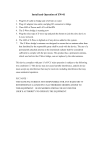
Physical Interface - EWS850AP
Mechanical & Environment
Length: 190 mm (7.48”)
Width: 124 mm (4.88”)
Depth: 47 mm (1.85”)
Weight: 720g
*Above information is device Only
Proection Level: IP67
Surge Protection: 1KV
ESD Protection: Contact 4KV / Air 8KV
1 2.4GHz Antennas Detachable 5.17dBi 5GHz Omni-directional
Antennas
2 5GHz Antennas Detachable 5.17dBi 2.4GHz Omni-directional
Antennas
3 LAN Port (802.3af/at PoE) : Ethernet port for RJ-45 cable.
4 LED Indicators: LED lights for Power, LAN Port , 2.4 GHz Connection and 5 GHz Connection. The color of LED light and active behavior is as below.
5 Mounting Holes: Using the provided hardware, the AP can be attached to a wall or pole.
*The installation angle of antenna must be vertical to the ground.
*This equipment i not suitable for use in locations where children are likely to be present.
1 2
3
4
1 2
5
10
Chapter 2
Before You Begin
11
Computer Settings
Windows XP/Windows 7/Windows 8/Windows
10
In order to use the Access Point, you must first configure the
TCP/IPv4 connection of your Windows OS computer system.
1a. Click the Start button and open the Control Panel
Windows XP Windows 7
1b . Move your mouse to the lower right hot corner to display the Charms Bar and select the Control Panel in
Windows 8 OS.
12
Windows 8
1c. In Windows 10, click Start to select All APPs to enter the folder of Windows system for selecting Control
Panel.
Windows 10
2a. In Windows XP, click Network Connections.
4. Select Internet Protocol Version 4 (TCP/IPv4) and then select Properties .
2b. In Windows 7/Windows 8/Windows 10 , click View
Network Status and Tasks in the Network and
Internet section, then select Change adapter settings.
3. Right click on Local Area Connection and select Properties.
5. Select Use the following IP address and enter an IP address that is different from the Access Point and Subnet mask, then click OK .
13
Note: Ensure that the IP address and Subnet mask are on the same subnet as the device.
For example: EWS850AP IP address: 192.168.1.1
PC IP address: 192.168.1.2 – 192.168.1.255
PC Subnet mask: 255.255.255.0
14
Apple Mac OS X
1.
Go to System Preferences (Which can be opened in the
Applications folder or selecting it in the Apple Menu).
2.
Select Network in the Internet & Network section.
.
Click Apply when done.
3.
Highlight Ethernet.
4.
In Configure IPv4 , select Manually.
5.
Enter an IP address that is different from the Access
Point and Subnet mask then press OK.
Note: Ensure that the IP address and Subnet mask are on the same subnet as the device.
For example: EWS850AP IP address: 192.168.1.1
PC IP address: 192.168.1.2 – 192.168.1.255
PC Subnet mask: 255.255.255.0
15
Hardware Installation
EWS850AP
1.
Connect one end of the Ethernet cable into the LAN
port (PoE) of the AP and the other end to the PoE port
on the PoE adapter.
2.
Connect the Power cord with the PoE Adapter and plug the other end into an electrical outlet.
3.
Connect the second Ethernet cable into the LAN port of the PoE adapter and the other end to the Ethernet port on the computer.
4. Screw on the provided antennas to the top of this device
5. When all the process is completed, the LED light will be active as below.
This diagram depicts the hardware configuration.
Note: The AP should ONLY be powered via Ethernet cable connected to the included PoE Adapter EPA5006GR. You can convert the device to factory default or users default via the reset button on
EPA5006GR.
16
Mounting the EWS850AP
Using the provided hardware, the device can be attached to a wall or a pole. The height should not exceed 2 meter.
1.
Wall Mounting Kit
Screw Set 1
-Anchors: Φ 6.6*16 mm
-Bolts: Φ 8*25mm
2. Pole Mounting Strap*2
Φ 66*12.6 mm
Anchors Bolts
Screw Set 2
-Screw - X type: Φ 13*42 mm
-Screw - P type: Φ 5.8*32 mm
17
Wall mounting the EWS850AP
A . Determine where the Access Point to be placed and mark location on the surface for the four mounting holes of wall mount base.
Pole mounting the EWS850AP
A . Thread the open end of the Pole Strap through the two tabs on the Pole Mount Bracket.
B.Lock and tighten Pole Strap to secure Pole Mount Bracket to the pole.
B .
Use the appropriate drill bit to drill two 8.1mm diagram and 26mm depth holes in the markings and hammer the bolts into the openings. Screw the anhors into the holes until they are flush with the wall.
C .
Screw the included screws into the anchors.
D. Slide the mount bracket into the slot of the Access
Point.
18
Chapter 3
Configuring Your
Access Point
19
Configuring Your Access Point
This section will show you how to configure the device by using the web-based configuration interface or EnGenius
EnWiFi App, which is a management tool to enable easy deployment on outdoor APs/CPEs. In conjunction with the
EnWifi App, outdoor APs/CPEs can perform configuration changes en-masse, monitoring, firmware upgrades, and data backups from a smart phone or tablet.
Web Interface Configuration
Default Setting
Please use your Ethernet port or wireless network adapter to connect the Access Point.
IP Address 192.168.1.1
Username / Password admin / admin
2.
The default username and password are admin .
Once you have entered the correct username and password, click the Login button to open the web-base configuration page.
* The model name will be varied by different models
3.
If successful, you will be logged in and see the device’s
User Interface.
1. Open a web browser (Internet Explorer/Firefox/Safari/
Chrome) and enter the IP Address http://192.168.1.1
Note: If you have changed the default LAN IP Address of the Access Point, ensure you enter the correct IP Address.
20
EnWiFi App Configuration
Download EnWiFi App
1.Please download and install EnWiFi App from Google Play or iOS App Market .
Android iOS
2. Before access to device, you need to find Management SSID and connect to it first. Then you can see your device in the Device List.
3. For more details of how to configure and management device via EnWiFi App, please see Chpater 9 EnWiFi App.
21
Chapter 4
Building a Wireless
Network
22
Before Starting
Before starting to configure this Access Point, you may realize the used scenario under varied operating modes. EWS850AP, built in the latest WiFi 6 (11ax) technology, can be configured as an: Access Point, Mesh or WDS (AP/Bridge/Station). This chapter describes purpose of different operating modes for the best deployment.
Access Point Mode
In Access Point Mode, device behaves likes a central connection for stations or clients that support IEEE 802.11ax networks and is backward competible. The stations and clients must be configured to use the same SSID (Service Set Identifier) and security password to associate with EWS850AP. The device supports up to eight (8) SSIDs per band at the same time for secure access.
WDS AP Mode
The device also supports WDS AP mode. This operating mode allows wireless connect to the other device via using WDS technology. In this mode, configure the MAC addresses in both Access Points to enlarge the wireless area by enabling
WDS Link settings. WDS supports up to four (4) AP MAC addresses.
WDS Bridge Mode
In WDS Bridge Mode, the device can wirelessly connect different LANs by configuring the MAC address and security settings of each device. Use this mode when two wired LANs located a small distance apart want to communicate with each other. The best solution is to use the device to wirelessly connect two wired LANs, as shown in the following diagram. WDS Bridge Mode can establish up to four WDS links, creating a star-like network.
Note: WDS Bridge Mode does not act as an Access Point. Access Points linked by WDS are using the same frequency channel. More Access Points connected together may lower throughput.
23
AP Mode
5GHz
5GHz
AP Mode
WDS AP WDS Bridge
24
WDS Station Mode
Station mode expands the WDS by receiving a wireless signal/service and sharing it through the Ethernet port.
WDS AP
WDS Station
25
WDS Station
Chapter 5
Overview Status
26
Main Status
Save Changes
This page lets you save and apply the settings shown under
Unsaved changes list , or cancel the unsaved changes and revert to the previous settings that were in effect.
Device Status
Clicking the Device Status link under the Overview menu shows the status information about the current operating mode.
• The Device Information section shows general system information such as Device Name, MAC Address, Current
Time, Firmware Version, and Management VLAN ID
Note: VLAN ID information is only applicable in Access
Point or WDS AP mode.
*The model name will be varied by different models.
*The model name will be varied by different models.
• The Memory Information section shows usage of memory such as Total Available, Free, Cached, Buffered
27
• The LAN Information section shows the Local Area
Network settings such as the LAN IP Address, Subnet mask, and DNS Address.
• The Statistics section shows Mac information such as
SSID, MAC address, RX and TX.
• The Wireless LAN Information 2.4GHz/5GHz section shows wireless information such as Operating Mode,
Frequency, and Channel. Since the AP supports multiple-
SSIDs, information about each SSID, the ESSID, and security settings, are displayed
Note: Profile Settings are only applicable in Access Point and WDS AP modes.
28
Connection
2.4GHz/ 5GHz Connection List
Click the connection link under the Overview menu displays the connection list of clients associated to the AP/CPE’s 5
GHz, along with the MAC addresses and signal strength for each client. Clicking Refresh updates the client list.
Note: Only applicable in Access Point and WDS AP modes.
WDS Link List
Click the connection link under the Overview menu. This page displays the current status of the WDS link, including
WDS Link ID, MAC Address, Link Status and RSSI.
Note: Only applicable in WDS AP and WDS Bridge modes.
29
Realtime
The Realtime section contains the following options:
CPU Loading: 3 minutes CPU loading percentage information, it displays current loading, average loading and peak loading status. Left bar is loading percentage; button is time tracing. The interval is every 3 seconds.
Traffic Loading: 2.4GHz/5GHz and Ethernet port inbound and outbound traffic by current, average and peak time.
30
Chapter 6
Network
31
Basic IP Settings
IPv4/IPv6 Settings
This page allows you to modify the device’s IP settings under Network->Basic.
Save: Click Save to confirm the changes.
Spanning Tree Protocol (STP) Settings
This page allows you to modify the Spanning Tree settings.
Enabling the Spanning Tree protocol will prevent network loops in your LAN network.
Spanning Tree Status : Enables or disables the Spanning
Tree function.
IP Network Settings: Select whether the device IP address will use a static IP address specified in the IP address field or be obtained automatically when the device connects to a DHCP server.
Hello Time : Specifies Bridge Hello Time in seconds. This value determines how often the device sends handshake packets to communicate information about the topology throughout the entire Bridged Local Area Network.
IP Address: The IP address of this device.
Subnet Mask: The IP Subnet mask of this device.
Max Age: Specifies Bridge Max Age in seconds. If another bridge in the spanning tree does not send a hello packet for a long period of time, it is assumed to be inactive.
Gateway: The Default Gateway of this device. Leave it blank if you are unsure of this setting.
Primary/Secondary DNS: The primary/secondary DNS address for this device.
Forward Delay: Specifies Bridge Forward Delay in seconds.
Forwarding delay time is the time spent in each of the
Listening and Learning states before the Forwarding state
32
is entered. This delay is provided so that when a new bridge comes onto a busy network, it analyzes data traffic before participating in the network.
Priority: Specifies the Priority Number. A smaller number has a greater priority than a larger number.
Save: Click Save to confirm the changes.
33
Wireless
Wireless Settings Wireless Network
*The model name will be varied by different models.
EWS850AP supports 802.11ax/ac/n/a mixed mode in 5
GHz and 802.11n/g/b mixed mode in 2.4GHz. 802.11ax mode in 2.4GHz is optional and can be enabled/disabled. .
Operation Mode: Select Operation Mode from Access
Point or WDS (AP, Bridge ,Station) base on the application scenario.
Device Name: Enter a name for the device. The name you type appears in SNMP management. This name is not the
SSID and is not broadcast to other devices.
Save: Click Save to confirm the changes.
Channel HT Mode: The default channel bandwidth is 20
MHz in 2.4GHz and 80MHz in 5GHz. The larger the channel, the greater the transmission quality and speed.
This page displays the current status of the Wireless settings of the AP.
Channel: Click Configuration button to open a new windows to configure channels for performing wireless service.
34
Transmit Power: Set the power output of the wireless signal.
Bit Rate: 2.4GHz and 5GHz can be controled by BAR via scroll from 6Mbps to 54Mbps.
Client Limits: If you set the limitation of client numbers , the maximum assocaited client devices will be restricted at this number. The client limits is default in127.
AP Detection: AP Detection can select the best channel to use by scanning nearby areas for Access Points.
11ax mode: This mode is optionnal for 2.4GHz, you can select Enable or Disale base on the application scenario.
Distance: Specifies the distance between Access Points and client devices. The proper setting for this parameter may assist Access Points to avoid the improper operation when transmitting data under a filed application.
35
SSID Profile
Current Profile: You can configure up to eight(8)different
SSIDs. If multiple client devices will be accessing the network, you can arrange the devices into SSID groups.
Click Edit to configure the profile and check whether you want to enable extra SSID.
VLAN Isolation: When this function is checked with specified VLAN ID in a SSID profile, the traffic from this
SSID will be tagged with this VLAN ID upon entering LAN bridge.
VLAN ID: Specifies the VLAN tag for each profile. If your netowrk includes VLANs, you can specify a VLAN ID for packets pass through the Access Point with a tag.
L2 Isolation: Enable this function prevenet client devices to communicate on the both WLAN and LAN.
The first SSID is default enabled and you can click Edit to specify the detail setting, including:
Enable: Click the check box to enable specific SSID interface.
The first SSID is default enabled.
SSID: Specifies the SSID name for the current profile.
Hidden SSID: Check this option to hide the SSID from clients.
If checked, the SSID will not appear in the site survey.
Client Isolation: Block the communication between the accociated clients under the same WLAN.
Band Steering: Enable this function to facilitate effective spectrum usage. 5GHz-capable clients can associate with
AP’s 5GHz radio and offloading air utilization in 2.4GHz band.
36
Wireless Security
The Wireless Security section lets you configure the AP’s security modes
Group Key Update Interval: Specifies how often, in seconds, the Group Key changes. The default value is 3600.
Secuirty Mode: Including OWE, WPA2-Personal, WPA3-
Personal, WPA2/WPA3-Personal, WPA2-Enterprise, WPA3-
Enterprise, WPA2/WPA3-Enterprise. The following is an example for WPA2-Enterprise (Pre-Shared Key).
Encryption: Default is AES. Please ensure that your wireless clients use the same settings.
Note: 802.11n does not allow WPA2-PSK TKIP security mode.
37
Radius Settings
NAS-IP: Configure you NAS server address to assign traffic to the destination.
NAS-Ports: Configure your port No. if you would like to enable Network Address Servecie (NAS) under a SSID.
NAS-ID: Configure a NAS ID which is mapped with the SSID.
The traffic will be forwarded via the different SSIDs if these
SSIDs configured as different ID.
Radius Accounting
Radius Accounting: Choose to enable or disable accounting feature.
Radius Accounting Server: Enter the IP address of the
Radius accounting server.
Radius Accounting Port Enter the port number used for connections to the Radius accounting server.
Radius Accounting Secret : Enter the secret required to connect to the Radius accounting server.
Interim Accounting Interval : Specifies how often, in seconds, the accounting data sends.
38
Fast Roaming
Enable the function to serve mobile client devices that roam from Access Point to Access Point. Some applications running on Client devices require fast re-association when they roam to a different Access Point
Please enter the settings of the SSID and initialize the Security mode to WPA2 or WPA3 enterprise, as well as to set the Radius
Server firstly. Then users can enable the Fast Roaming and implement the advanced search.
Please also set the same enterprise Encryption under the same SSID on other Access Points and enable the
Fast Roaming. When the configuration is realized on different Access Point, the mobile client devices can run the voice service and require seamless roaming to prevent delay in conversation from Access Point to Access Point.
39
Wireless MAC Filtering
Wireless MAC Filtering is used to allow or deny network access to wireless clients (computers, tablet PCs, NAS, smartphones, etc.) according to their MAC addresses. You can manually add a MAC address to restrict permission to access the AP. The default setting is: Disable Wireless
MAC Filter .
Note: Only applicable in Access Point and WDS AP modes.
ACL Mode: Determines whether network access is granted or denied to clients whose MAC addresses appear in the
MAC address table on this page. There are three optoin:
Disabled / Allow MAC in the list / Deny MAC in the list.
MAC Address: Enter the MAC address of the wireless client.
Add: Click Add to add the MAC address to the MAC address table.
40
Wireless Traffic Shaping
Traffic shaping regulates the flow of packets leaving an interface to deliver improved Quality of Service(QoS). The function will allow administrators to restrict the wireless bandwidth per SSID or per user.
Management Interface-2.4G
This Management interface make you can change the configuration via EnWiFi App instead of using the GUI.
Management SSID will be turned off in this two situation.
(1)When the device is powered up in the first time and there is no connection in 30 minutes. (2)When the setting is done and idle in 15 minutes. If you need to turn on management
SSID please reboot the device.You can set to always on or turn off if idle in 15 minutes.
For security, we strongly recommend to change the default passphrase via entering the Edit page.
Status : Check this option to enable Wireless Traffic Shaping.
Download Limit: Specifies the wireless transmission bandwidth used for downloading.
Upload Limit: Specifies the wireless transmission bandwidth used for uploading.
This limitation can be specified per user.
After filling in those settings, click Save to confirm then back to the main page of wireless setting.
41
Guest Network Settings
You can add a guest network which allows visitors to use the Internet without providing your office or company wireless security key. You can checked the guest network in specified SSID and proceed the detail setting here.
IP Address: The IP Address of this device.
Subnet Mask: The IP Subnet mask of this device.
Automatic DHCP Server Settings
Starting IP Address: The first IP Address in the range of the addresses by the DHCP server.
Ending IP Address: The last IP Address in the range of addresses assigned by the DHCP server.
WINS server IP: Address for the WINS server.
42
Management VLAN Settings
This page allows you to assign a VLAN tag to packets sent over the network. A VLAN is a group of computers on a network whose software has been configured so that they behave as if they were on a separate Local Area Network
(LAN). Computers on VLAN do not have to be physically located next to one another on the LAN.
Note: Only applicable in Access Point and WDS AP modes.
Management VLAN : If your network includes VLANs, you can enable Management VLAN ID for packets passing through the Access Point with a tag.
Save: Click Save to confirm the changes or Cancel to cancel and return to previous settings.
Note: If you reconfigure the Management VLAN ID, you may lose your connection to the EnStationAC. Verify that the DHCP server supports the reconfigured VLAN
ID and then reconnect to the EnStationAC using the new IP address.
43
Chapter 7
Mesh
44
Mesh
Mesh Status
This page allows you to review the status of the mesh network.
Mesh ID: To create a mesh network, please enter the ID number of this device for including into Mesh.
Password: Set up a password for this Mesh ID.
Mesh RSSI: The RF level in the mesh network.
Save/Cancel: To instore or remove the setings you have done.
Mesh Settings
This page allows you to build up a mesh connection in the wireless network.
Mesh: Choose to enable or disable.
Operation Mode: Base on the role of this device to make it as Mesh AP or Mesh Point.
Mesh Device Name: The modle name of this Mesh device.
45
Tools
Node List: Devices list in this Mesh network.
Link Status: This page allows you to review the linking status (RSSI) of each Mesh nodes.
Traceroute
This page allows you to trace the routing table to a target in the network.
Ping
This page allows you to analyze the connection quality of the device in the network.
From/To: Choose the IP address you would like to trace.
Start: Click start to proceed traceroute test.
From/To: Choose the IP address you would like to ping in this Mesh network.
Number of Pings: Enter the number of times you wish to ping.
Start: Click start to proceed ping test.
Throughput Test
Chroose the target device you would like to test the throughput performance.
46
Chapter 8
Management
47
Advanced Settings
Controller Settings
Controller Address (Auto detection if leave empty) :
If the device is managing by controller, it will show the address.
SNMP Settings
This page allows you to assign the Contact Details, Location,
Community Name, and Trap Settings for a Simple Network
Management Protocol (SNMP). SNMP is a networking management protocol used to monitor network attached devices. SNMP allows messages (called protocol data units) to be sent to various parts of the network. Upon receiving these messages, SNMP compatible devices (called agents) returns the data stored in their Management Information
Bases.
Status : Enables or disables the SNMP feature.
Contact: Specifies the contact details of the device.
Location: Specifies the location of the device.
Community Name (Read Only): Specifies the password for the SNMP community for read only access.
Community Name (Read/Write): Specifies the password for the SNMP community with read/write access.
Trap Destination Address: Specifies the IP address of the computer that will receive the SNMP traps.
Trap Destination Community Name: Specifies the password for the SNMP trap community.
48
SNMPv3: Enables or disables the SNMPv3 feature.
User Name: Specifies the username for SNMPv3.
Auth Protocol : Selects the authentication protocol type:
MDS or SHA.
SAuth Key: Specifies the authentication key.
Priv Protocol: Selects the privacy protocol type: DES.
Priv Key: Specifies the privacy key for privacy.
Engine ID: Specifies the engine ID for SNMPv3.
Apply Save: Click Apply Save to apply the changes.
SSH : Enable Secure Shell (SSH) to make secure, encrypted connections in the network. Secure Shell is a network protocol that allows data to be exchanged using a secure channel between two network devices.
HTTPS: Enable HTTPS to transfer and display web content securely. The Hypertext Transfer Protocol over SSL (Secure
Socket Layer) is a TCP/IP protocol used by web servers to transfer and display web content securely.
CLI Settings
CLI : The Command Line Interface (CLI) allows you to type commands instead of choosing them from a menu or selecting an icon.
49
Email Alert
You can use the Email Alert feature to send messages to the configured email address when particular system events occur.
Note: Do NOT use your personal email address as it can unnecessarily expose your personal email login credentials.
Use a separate email account made for this feature instead
Password: Enter the password for the email account that will be used to send emails.
SMTP Server: Enter the IP address or hostname of the outgoing SMTP server.
Port: Enter the SMTP port number to use for outbound emails.
Security Mode: Selects the security mode: SSL/TLS or
STARTTLS or None.
Apply: To save setting and take effect.
From: Enter the email address to show the sender of the email.
To: Enter the address that you wish to send emails to.
Subject: Enter the text that you wish to appear in the email’s subject line.
Username: Enter the username for the email account that will be used to send emails.
50
Time Zone
Date and Time Setting
This page allows you to set the internal clock of the device.
Time Zone
You can click Auto Detect or select Time Zone from the menu.
Enable Daylight Saving : Check whether daylight savings applies to your area.
Start : Select the day, month, and time when daylight savings time starts.
End : Select the day, month, and time when daylight sav ings times ends.
Manually Set Date and Time: Manually specify the date and time.
Automatically Get Date and Time: Select and check whether you wish to enter the IP address of an NTP server or use the default NTP server to have the internal clock set automatically.
51
Auto Reboot Settings
You can specify how often you wish to reboot the device.
Auto Reboot Setting : Enables or disables the Auto
Reboot function.
Frequency of Auto Reboot : Specifies how often you wish to reboot the EnStationAC by Min, Hour, Day or
Week.
Timer : Select the day and enter the time you would like to reboot automatically.
Save : Click Save to apply the changes.
52
Wi-Fi Scheduler
The Wi-Fi Scheduler can be created for use in enforcing rules. For example, if you wish to restrict web access to
Mon-Fri from 3pm to 8pm, you could create a schedule selecting Mon, Tue, Wed, Thu and Fri while entering a Start time of 3pm and End Time of 8pm to limit access to these times.
drop-down list.
Day(s): Place a checkmark in the boxes for the desired days or select the All Week radio button to select all seven days of the week.
Duration: The Start Time is entered in two fields. The first box is for hours and the second box is for minutes. The End
Time is entered in the same format as the Start time.
Status: Enables or disables the Wi-Fi scheduler function.
Wireless Radio: Select 2.4 GHz or 5 GHz from the drop- down list for the preferred band type.
SSID Selection: Select a SSID from the drop-down list.
Schedule Templates: Select a schedule template from the
53
Tools
Ping Test Traceroute Test
This page allows you to analyze the connection quality of the device and trace the routing table to a target in the network.
Target IP/ Domain Name: Enter the IP address or domain name you would like to trace
From/To: Enter the IP address you would like to ping.
Target IP: Enter the IP address you would like to search.
Ping Packet Size: Enter the packet size of each ping.
Number of Pings: Enter the number of times you wish to ping.
Start: Click start to proceed ping test.
Nslookup Test
Target IP/ Domain Name: Enter the IP address or domain name you would like to do Nslookup test.
54
Speed Test
Target IP / Domain Name: Enter an IP address or domain name you wish to impelement a speed test for realizing the variance on wireless speed.
Time Period: Enter the time in seconds that you would like the test to implement for and in how many intervals.
IPv4/IPv6 Port : This Access Points uses IPv4 5001 and
IPv6 60001 port for the speed test.
Start : Click start to implement speed test.
Device Discovery
This page allows you to discover devices from network for Operation Mode, IP Address, System MAC Address and
Firmware version.
55
Chapter 9
System Management
56
System Manager
Account Firmware
This page allows you to change the device username and
Firmware Upgrade
password. By default, the username is: admin and the
This page allows you to upgrade the firmware of the password is: admin . The password can contain from 0 to device.
12 alphanumeric characters and is case sensitive.After this changes applies, you need to login again.
Account Settings
To Perform the Firmware Upgrade:
1. Click the Choose File button and navigate the OS file system to the location of the upgrade file.
Administrator Username : Enter a new username for logging in to the New Name entry box.
Current Password: Enter the old password for logging in to the Old Password entry box.
New Password: Enter the new password for logging in to the New Password entry box.
Verify Password: Re-enter the new password in the
Confirm Password entry box for confirmation.
2. Select the upgrade file. The name of the file will appear in the Upgrade File field.
3. Click the Upload button to commence the firmware upgrade.
Note: The device is unavailable during the Firmware upgrade process and must restart when the upgrade is completed. Any connections to or through the device will be lost.
Apply: Click Apply to apply the changes.
57
Backup/Restore User Setting
This page allows you to save the current device configurations. When you save your configurations, you also can reload the saved configurations into the device through the Restore Saved Settings from a file section. If extreme problems occur, or if you have set the AP incorrectly, you can use the Reset button in the
Revert to Factory Default Settings section to restore all the configurations of the AP to the original default settings.
The function allows you to backup the current device configurations into the EnStationAC as the default value. If extreme problems occur, or if you have set the
EnStationAC incorrectly, you can push the Reset button to revert all the configurations of the EnStationAC to the user default.
Back Up Setting as Default: Click Backup to backup the user settings you would like to the device’s memory for the default settings.
Factory Setting
Restore to User Default : Click Restore to restore user settings to the factory standard settings.
Backup Setting: Click Export to save the current configured settings.
Restore New Setting: To restore settings that have been previously backed up, click Browse , select the file, and click Restore .
Restore to Default: Click Reset button to restore the
AP to its factory default settings.
58
Note1: After setting the current settings as the default, you should click the Restore to Default on the web interface for reverting the settings into the factory default instead of pushing the reset button.
Note2: Please write down your account and password before saving. The user settings will now become the new default settings at the next successful login.
59
Log
System Log Remote Log
The EnStationAC automatically logs (records) events of possible interest in its internal memory. To view the logged information, click the Log link under the System
Manager menu. If there is not enough internal memory to log all events, older events are deleted from the log.
When powered down or rebooted, the log will be cleared.
This page allows you to setup the Remote Log functions for the AP/CPE.
Syslog: Enables or disables the syslog function.
Log Server IP Address: Enter the IP address of the log server.
Remote Log: Enable or disable the remote log service.
Apply: Click Apply to apply the changes.
Status : Enable/Disable this function.
Trafic Log : Enable/Disable this function.
Log type
:
You may choose one of log types to display logs in the following window. The default log types is All.
60
Logout
Click Logout in Management menu if you want to logout from the device.
Reset
In some circumstances, it may be required to force the device to reboot. Click on Reset to reboot or to reset the device.
*The model name will be varied by different models.
Please confirm again to logout the system or not.
*The model name will be varied by different models.
Once you click reset button, you will see the options for reboot or restore this AP.
Reboot the device: Click it to reboot this device.
Restore to Factory Default: Click it to reset this device to factory default setting.
Restore to User Default: Click it to reset this device to user default settings.
61
Chapter 10
EnWiFi App
62
About EnWiFi App
EnWiFi is a convenient Wi-Fi management tool for EnGenius-brand outdoor and indoor Wi-Fi devices. Configure and monitor
EnGenius Wi-Fi device from a smartphone or tablet. EnWifi offers single or group device configuration and updates on your network’s latest status. You can access to EnGenius devices anytime via EnWiFi.
Features
Single Configuration
Proceed single device configuration throughout EnWiFi App. The Configuration could be assisted users to fulfill settings on
Wireless, Network and Systems.
Group Configuration
Users can create a group configuration for multiple wireless access points and change between Client Bridge, WDS AP, WDS
Bridge, WDS Station modes and EnGenius ERP easily.
Device Management
Realize status of an Access Point on RF information and real time throughput on Tx and Rx ways to make maximum PtP connecting performance or remove device with weak signal.
Discover Device
Discover EnGenius Device nearby and access to it to do management quickly.
Connected Status Monitor
Monitor connected devices on signal level (RSSI), transmit / receive performance, and firmware version. Users can enhance device settings base on these connected information.
Backup and Restore
Backup current configuring file and restore to other devices quickly.
63
Configuring Device in EnWiFi App
Before access to device, you need to find Management SSID and connect to it first. Then you can see your device in the Device
List.
Single Configuration
Proceed Wireless Settings, Network and System Configuration to setup value on RF parameters, DHCP/Spanning Tree, and time zone for a device.
64
WDS Link
Setting WDS links will assist users to setup peer-to-peer connection easily.
65
Group Configuration
Proceed Wireless Settings including EnJet, Operation mode, distance and time slot, channel used, channel HT, Tx power and
Security
66
Group Configuration
Proceed Wireless Settings including EnJet, Operation mode, distance and time slot, channel used, channel HT, Tx power and
Security
67
Proceed configuration on IP/Subnet, time Setting, and account/password under a group.
68
You also can use EnWiFi App to proceed connection from Client Bridge mode devices to an Access Point mode device.
69
You also can set Operation mode to WDS AP mode and let WDS STA devices connect to this WDS AP mode device.
70
Discover Device
Discover and Access to other EnGenius devices to manage their status.
71
Monitor & Management
Monitor clients connected status. Base on this information to adjust configuration or press kick out to remove device if the signal is weak .
72
Backup
Backup current settings as a configuration file to apply to other devices quickly.
73
Restore
Choose backup file to restore other devices so that they can have the same configuration quickly.
74
Appendix
75
Appendix A - FCC Interference Statement
Federal Communication Commission Interference Statement
This device complies with Part 15 of the FCC Rules. Operation is subject to the following two conditions: (1) This device may not cause harmful interference, and (2) this device must accept any interference received, including interference that may cause undesired operation.This device and its antenna(s) must not be co-located or operating in conjunction with any other antenna or transmitter.For product available in the USA/Canada market, only channel 1~11 can be operated. Selection of other channels is not possible.Section 15.204(b) states that an approved “transmission system” must always be marketed as a complete system including the antenna.
This equipment has been tested and found to comply with the limits for a Class B digital device, pursuant to Part 15 of the FCC Rules. These limits are designed to provide reasonable protection against harmful interference in a residential installation. This equipment generates, uses and can radiate radio frequency energy and, if not installed and used in accordance with the instructions, may cause harmful interference to radio communications.
However, there is no guarantee that interference will not occur in a particular installation. If this equipment does cause harmful interference to radio or television reception, which can be determined by turning the equipment off and on, the user is encouraged to try to correct the interference by one of the following measures:
• Reorient or relocate the receiving antenna.
• Increase the separation between the equipment and receiver.
• Connect the equipment into an outlet on a circuit different from that to which the receiver is connected.
• Consult the dealer or an experienced radio/TV technician for help
FCC Caution:
Any changes or modifications not expressly approved by the party responsible for compliance could void the user’s authority to operate this equipment.
This transmitter must not be co-located or operating in conjunction with any other antenna or transmitter.
IMPORTANT NOTE:
Radiation Exposure Statement
This equipment complies with FCC radiation exposure limits set forth for an uncontrolled environment. This equipment should be installed and operated with a minimum distance of 20 cm between the radiator & your body.
76
Appendix B - Professional Installation Instruction (FCC)
Installation Personal
This product is designed for specific application and needs to be installed by a qualified personal who has RF and related rule knowledge. The general user shall not attempt to install or change the setting.
Installation Location
The product shall be installed at a location where the radiating antenna can be kept 20 cm from nearby person in normal operation condition to meet regulatory RF exposure requirement.
External Antenna
Use only the antennas which have been approved by the applicant. The non-approved antenna(s) may produce unwanted spurious or excessive
RF transmitting power which may lead to the violation of FCC limit and is prohibited.
Installation Procedure
Please refer to user’s manual for the detail.
Warning:
Please carefully select the installation position and make sure that the final output power does not exceed the limit set force in relevant rules. The violation of the rule could lead to serious federal penalty.
77
Appendix C - IC Interference Statement
Industry Canada statement
This device contains licence-exempt transmitter(s)/receiver(s) that comply with Innovation, Science and Economic Development
Canada’s licence-exempt RSS(s). Operation is subject to the following two conditions:
1. This device may not cause interference.
2. This device must accept any interference, including interference that may cause undesired operation of the device.
Le présent appareil est conforme aux CNR d’ ISED applicables aux appareils radio exempts de licence. L’exploitation est autorisée aux deux conditions suivantes : (1) le dispositif ne doit pas produire de brouillage préjudiciable, et (2) ce dispositif doit accepter tout brouillage reçu, y compris un brouillage susceptible de provoquer un fonctionnement indésirable.
Caution: where applicable, antenna type(s), antenna models(s), and worst-case tilt angle(s) necessary to remain compliant with the e.i.r.p. elevation mask requirement set forth in section 6.2.2.3 shall be clearly indicated.
Avertissement: lorsqu’il y a lieu, les types d’antennes (s’il y en a plusieurs), les numéros de modèle de l’antenne et les pires angles d’inclinaison nécessaires pour rester conforme à l’exigence de la p.i.r.e. applicable au masque d’élévation, énoncée à la section 6.2.2.3, doivent être clairement indiqués.
78
IMPORTANT NOTE:
Radiation Exposure Statement
This equipment complies with ISED radiation exposure limits set forth for an uncontrolled environment. This equipment should be installed and operated with minimum distance 20cm between the radiator & your body.
Déclaration d’exposition aux radiations:
Cet équipement est conforme aux limites d’exposition aux rayonnements ISED établies pour un environnement non contrôlé. Cet
équipement doit être installé et utilisé avec un minimum de 20 cm de distance entre la source de rayonnement et votre corps.
DETACHABLE ANTENNA USAGE
This radio transmitter (IC: 10103A-EWS850AP ) has been approved by ISED to operate with the antenna type listed below with maximum permissible gain indicated. Antenna types not included in this list, having a gain greater than the maximum gain indicated for that type, are strictly prohibited for use with this device.
Le présent émetteur radio (IC: 10103A-EWS850AP ) a été approuvé par ISED pour fonctionner avec les types d’antenne énumérés ci-dessous et ayant un gain admissible maximal. Les types d’antenne non inclus dans cette liste, et dont le gain est supérieur au gain maximal indiqué, sont strictement interdits pour l’exploitation de l’émetteur.
Approved antenna(s) list
EWS850AP
Type
2.4GHz Dipole
5 GHz Dipole
Gain
5.17dBi
5.17dBi
Brand Manufacturer
Master Wave Technology Master Wave Technology
Master Wave Technology Master Wave Technology
79
Appendix D
Professional installation instruction (IC)
1. Installation personal
This product is designed for specific application and needs to be installed by a qualified personal who has RF and related rule knowledge. The general user shall not attempt to install or change the setting.
2. Installation location
The product shall be installed at a location where the radiating antenna can be kept 20cm from nearby person in normal operation condition to meet regulatory RF exposure requirement.
3. External antenna
Use only the antennas which have been approved by the applicant. The non-approved antenna(s) may produce unwanted spurious or excessive RF transmitting power which may lead to the violation of FCC/ISED limit and is prohibited.
4. Installation procedure
Please refer to user’s manual for the detail.
5. Warning
Please carefully select the installation position and make sure that the final output power does not exceed the limit set force in relevant rules. The violation of the rule could lead to serious federal penalty.
80
Instructions d’installation professionnelle
1. Installation
Ce produit est destine a un usage specifique et doit etre installe par un personnel qualifie maitrisant les radiofrequences et les regles s’y rapportant. L’installation et les reglages ne doivent pas etre modifies par l’utilisateur final.
2. Emplacement d’installation
En usage normal, afin de respecter les exigences reglementaires concernant l’exposition aux radiofrequences, ce produit doit etre installe de facon a respecter une distance de 20cm entre l’antenne emettrice et les personnes.
3. Antenn externe.
Utiliser uniiquement les antennes approuvees par le fabricant. L’utilisation d’autres antennes peut conduire a un niveau de rayonnement essentiel ou non essentiel depassant les niveaux limites definis par FCC/ISED, ce qui est interdit.
4. Procedure d’installation
Consulter le manuel d’utilisation.
5. Avertissement
Choisir avec soin la position d’installation et s’assurer que la puissance de sortie ne depasse pas les limites en vigueur. La violation de cette regle peut conduire a de serieuses penalites federales.
81
advertisement
Related manuals

advertisement