advertisement

NOTE:
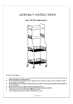
Please read all instructions carefully before using this product
Table of Contents
Safety Notice
Hardware Identifier
Assembly Instruction
Parts List
OWNER’S MANUAL
JX-1300
3 Station Home Gym with 145LBS pin
l
oaded weight stack
Model
SPARTAN
Retain This
Manual for
Reference
2017-2-13
OWNER'S
MANUAL
TABLE OF CONTENTS
BEFORE YOU BEGIN....................................................................................……….. 1
IMPORTANT SAFETY NOTICES...................................................................……….. 2
HARDWARE PACK……….....….....................................................................……….. 3
ASSEMBLY INSTRUCTIONS.........................................................................……….. 6
CARE AND MAINTANENCE
.......................................................
.22
PARTS LIST………………………………………………………………………………….. 23
BEFORE YOU BEGIN.
Thank you for selecting the JX-1300 Three Station Home Gym
.
For your safety and benefit, read this manual carefully before using the machine.
As a manufacturer, we are committed to provide you complete customer satisfaction.
If you have any questions, or find there are missing or damaged parts, we guarantee you complete satisfaction through direct assistance from our factory.
1
IMPORTANT SAFETY NOTICE
PRECAUTIONS
This exercise machine is built for optimum safety. However, certain precautions apply whenever you operate a piece of exercise equipment. Be sure to read the entire manual before you assemble or operate your machine. In particular, note the following safety precautions:
1.
Keep children and pets away from the machine at all times. DO NOT leave children unattended in the same room with the machine.
2. Only one person at a time should use the machine.
3. If the user experiences dizziness, nausea, chest pain, or any other abnormal symptoms, STOP the workout at once. CONSULT A PHYSICIAN
IMMEDIATELY.
4. Position the machine on a clear, leveled surface. DO NOT use the machine near water or outdoors.
5. Keep hands away from all moving parts.
6. Always wear appropriate workout clothing when exercising. DO NOT wear robes or other clothing that could become caught in the machine. Running or aerobic shoes are also required when using the machine.
7. Use the machine only for its intended use as described in this manual. DO
NOT use attachments not recommended by the manufacturer.
8. Do not place any sharp object around the machine.
9. Disabled person should not use the machine without a qualified person or physician in attendance.
10. Before using the machine to exercise, always do stretching exercises to properly warm up.
11. Never operate the machine if the machine is not functioning properly.
12. A spotter is recommended during exercise.
WARNING: BEFORE BEGINNING ANY EXERCISE PROGRAM, CONSULT YOUR
PHYSICIAN.
THIS IS ESPECIALLY IMPORTANT FOR INDIVIDUALS OVER THE
AGE OF 35 OR PERSONS WITH PRE-EXISTING HEALTH PROBLEMS.
READ
ALL INSTRUCTIONS BEFORE USING ANY FITNESS EQUIPMENT.
WE
ASSUME NO RESPONSIBILITY FOR PERSONAL INJURY OR PROPERTY
DAMAGE SUSTAINED BY OR THROUGH THE USE OF THIS PRODUCT.
SAVE THESE INSTRUCTIONS.
2
HARDWARE
3
4
5
Assembly step
It is strongly recommend that two or more person assemble this three station home gym.
Tool required assembly the machine: two adjustable wrenches, and one Philips screw driver
Carefully unpack each component ,checking against the part list that you have all the necessary parts to complete the assembly.
STEP 1
A)Insert the 2 pcs Guide Rod ( 13# ) into the two holes on the rear stabilizer
( 2# ) ,And secure them with 2pc M10×25 Allen bolt ( 90# ) and 2pcs φ10 Washer
(100#), And then slide 2 pcs rubber bumper(57#) onto the Guide Rods from the top to the bottom.
Do not fully tighten the bolts and nuts until getting instruction.
B.) Attach the Main base frame (1#) to the Rear Stabilizer(2#) , Secure them with 2 pcs
M10×70 Carriage Bolt ( 89# ) , one pc U- Shaped Bracket ( 38# ) ,2pcs φ10
Washer(100#) and 2pcs M10 Aircraft nut (97#) .
C.) Attach the Front vertical frame (3#) onto the Main base frame (1#), And Secure them with 2pc M10X70 Carriage Bolt(89#), 1 pc bracket(31#),2 pcs φ 10
Washer(100#) and 2 pcs Aircraft nut (97#).
6
SETP 2
A)Slide 14 pcs Weight Plate ( 45# ) onto the Guide Rods ( 13# ) from the top to the bottom , Make sure all the deep grooves on the weight plates face the Front and downwards. Align the holes and Insert the Selector Rod ( 12# ) into the hole on the weight plates , and then place the Selector Stem ( 44# ) onto the Selector Rod(12#).
Select the desired number of Weight Plate with L-Shaped Pin ( 93# ) when doing the exercise ;
B)Place the Upper Frame (4#)Onto the 2 PCS Guide Rod ( 13# ) and align the holes,
Secure them with 2PCS M10 × 25 Allen Bolt ( 90# )、 2PCS φ10 Washer(100#) .
C ) Attach the Upper Frame (4#) onto the Front Vertical Frame(3#) and Secure them with 2 pcs M10 × 90 Carriage Bolt ( 88#), one Bracket (31#),2PCS φ 10 Washer
( 100# ) ,2PCS M10 Aircraft Nut ( 97# ) .
7
STEP 3
A) Attach the Front Press Frame(5#) to the Upper Frame(4#),Secure them with Front press
Axle(91#), Two Pcs φ 10 Washers ( 100 #) and 2PCS M10 Aircraft Nut ( 97 #) . Do not fully tighten the bolts and nuts.
Make sure the Front Press Frame (5#) can swivel freely.
B) Attach the Right Butterfly Frame (8#) to the Front press Frame(5#),and secure them with
1 pc Allen Bolt(108#),1 PC Lock Ring(59#) and 1PC M6 Aircraft Nut(95#). Insert the Foam
Roll (71#)into the Right butterfly(8#) from the bottom to the mid of the right butterfly, attach the front press handle (10#) to the right Butterfly(8#) and then Secure them with
1PC M10*85 Allen bolt(87#).
C) Repeat the procedure B to install the left butterfly(7#).
D) Attach the Backrest pad (39#) to the Front Vertical frame(3#) and Secure them with
2PCS M8*85 Allen Bolts (111#)and 2PCS φ 8 Washers(101#).
E) Attach the Pulley Bracket(16#) to the Front Vertical Frame(3#) and Secure them with one pc M10*110 Allen Bolt(86#),2pcs φ 10 Washers (100#) and one M10 Aircraft
Nut(97#).Attach the Swivel Pulley Bracket (19#) to the pulley bracket(16#) and Secure them with M10*65 Allen Bolt(109#), two PCS φ 10 Washers(100#) and M10 Aircraft
Nut(97#).Install the another Swivel bracket(19) with the same method.
8
STEP 4
A) Attach the Seat Support Frame (6#) to the Front Vertical Frame(3#) and Secure them with two pcs M10*90 Carriage Bolt(88#), one pc Bracket(35#) two pcs φ 10
Washers(100#), and two pc M10 Aircraft Nut(97#).
B) Attach the Leg Developer (9#) to the front of the Seat Support Frame(6#) and
Secure them with two pcs M10*16 Allen Bolt(105#), two pcs φ 10
Washers(100#),one PC Swivel Axle(92#). Do not tighten the bolts and make sure the
Leg developer can swivel freely. Insert the Arm Curl Stand (11#) into the top opening of the Seat Support Frame(6#) and choose different height with lock knob(63#).
C) Place the Seat Pad (40#) onto the Seat Support Frame(6#), and Secure them with
Two pcs M8*65 Allen Bolts(112#), two pcs φ 8 washers(101#) . Place the Arm Curl
Pad (41#) onto the Arm Curl Pad Support(11#) and Secure them with 2pcs M8*16
Allen Bolts(106#), Two φ 8 washers(101#).
D) Insert one pc Foam Roll Tube(33#) into the hole of Seat Support Frame (6#)halfway, another Roll Foam Tube into the hole of Leg Developer(9#). Place the four Foam rolls(70#) onto the Foam Roll Tube (33#) from two ends. And then insert the four
End Cap (51#) into the Foam Roll Tube(33#).
E) Attach 2pcs Foot Plate(20#) to the Main Base Frame(1#), Secure them with 2pcs
Carriage Bolts(88#),two Pcs φ 10 washers(100#) and M10 Aircraft Nuts(97#)
9
STEP 5
A) Attach the Upper Cable(75#) through the bracket of Upper frame(4#), Make sure that the ball stopper should be underneath the frame.
B) Attach one pc Pulley (60#) to the bracket and secure them with one pc
M10*45 Allen Bolt(104#), two pcs φ 10 washer(100#) and one pc M10 Aircraft
Nut(97#).
C) Draw the Upper cable(75#) backwards and to the top bracket of the vertical frame(3#) and then repeat the procedure B to install a pulley.
D) Draw the cable towards the pulley and through the centre of the front press frame(5#) and then repeat the procedure B to install one pc pulley.
E) Draw the Upper cable(75#) backwards through the hole on the front vertical frame(3#)and repeat the procedure B to install one pc pulley.
F) Draw the Upper cable(75#)downwards and place one pc pulley onto the cable ,
Secure the pulley to the double floating pulley bracket(17#) with one pc
M10*45 Allen Bolt(104#), two pcs φ 10 washer(100#) and one pc M10 Aircraft
Nut(97#).
G) Draw the cable around the pulley upwards , place two pcs pulley to the opening of rear of the upper frame (4#) and secure them with two pcs
M10*45Allen Bolt(104#) ,four pcs φ 10 washer(100#) ,two pcs L-shape separation blade(117#),two pcs M10 Aircraft Nut(97#).
H) Draw the cable downwards between the two Guide Rod(13#)to the Selector
Rod (12#),thread the bolt into the opening on the top of the Selector Rod to secure the cable.
NOTE: Tighten or loosen the end bolt of the upper cable(75#)can adjust the tension of the cable system. Please make sure the bolt screw inside of the weight selector rod (12#) at least 5 laps.
10
11
STEP 6
A) Attach one end of the butterfly Cable (76#)to the hook on the right butterfly(8#).
Place one pc Pulley (60#) under the cable, and position the pulley into the
Swivel Pulley bracket(19#),and secure them with one pc M10*45 Allen bolt(104#),two pcs φ 10 washer(100#),one M10 Aircraft Nut(97#).
B) Draw the Butterfly Cable (76#)downwards, place one pc pulley (60#) onto the cable and secure the pulley to the Cross double floating pulley bracket
(18#)with one pc M10*45 Allen bolt(104#),two pcs φ 10 washer(100#),one M10
Aircraft Nut(97#).
Note: let the pulley assembly hanging at this stage.
C) Draw the cable upwards around the pulley. Repeat the Procedure B to install the pulley to left side swivel pulley bracket.
D) Attach another end of the butterfly cable (76#) to the hook on the left butterfly.
12
STEP 7
A ) Remove the Double Strap Buckle(74#) and ball stopper from the end of Lower cable(77#) , so that the lower cable(77#) would go through the holes .
B)Attach the low cable(77#) to the opening of the leg developer(9#),make sure that the ball stopper should be on the front of the leg developer. Attach one pc Pulley
(60#) into the opening and secure them with one pc M10*45 Allen bolt(104#),two pcs φ 10 washer(100#),one M10 Aircraft Nut(97#).
C)Attach the cable backwards of the machine through the second bracket and the opening of the front vertical frame(3#),attach two pcs pulley(60#) onto the cable and secure them with two pc M10*45 Allen bolt(104#),four pcs φ 10 washer(100#),two M10 Aircraft Nut(97#).
D)Draw the cable upwards, place one pc pulley(60#) behind the cable and Secure the pulley to the another side of Cross double floating pulley bracket(18#).
E)Draw the cable downwards, place one pc pulley onto the cable and secure the pulley to the bracket with one pc M10*45 Allen bolt(104#),two pcs φ 10 washer(100#),one M10 Aircraft Nut(97#).
F)Draw the cable upwards, and place one pc pulley behind the cable, Attach the pulley to the double floating pulley bracket and secure them with one pc M10*45
Allen bolt(104#),two pcs φ 10 washer(100#),one M10 Aircraft Nut(97#).
G)Draw the cable downwards and place one pc pulley onto the cable, and then secure the pulley to the bracket of the front vertical frame(3#).
H)Draw the cable upwards, through the opening of the front vertical frame(3#), place one pc pulley into the opening and secure it with one pc M10*65 Allen bolt(109#),two pcs φ 10 washer(100#),and one M10 Aircraft Nut(97#).
I)Attach the Double Strap Buckle(74#) to the end of low cable(77#), and secure them with one pc M10*30 Allen Bolt(113#), two pcs φ 10 washer(100#), and one pc M10
Aircraft Nut(97#).
13
14
STEP 8
A) Attach the left & Right Weight stack Cover(36&37) together, and Secure them with four pcs Philips Screw (107#) and four M5 aircraft Nut(96#).
B) Place the left & Right Weight Stack Cover(36&37)onto the Rear Stabilizer(2#) and Secure them with 6PCS M10*16 Allen Bolts(105#),6pcs φ 10 washer(100# ) .
15
STEP 9
A)
Attach the left side Stabilizer (23#)and right side stabilizer(24#) to the Main base
Frame(1#), And secure them with two pcs M10*90 Carriage Bolt(88#),two pcs Ø 10 washers(100#) and two pcs M10 aircraft Nuts(97#).
B)
Attach the lower vertical frame (26#) to the right side stabilizer stabilizer(24#), and secure them with two pcs M10*70 Carriage Bolt (89#), one pc bracket(35#),two pcs
Ø 10 washers (100#),Two pcs Aircraft Nuts(97#).
16
Step 10
A) Attach the upper Vertical Frame (27#) to the lower vertical Frame(26#).
B) Attach the left Dip Arm( (29#),right Dip Arm(30#),upper vertical frame(27#) ,lower vertical frame (26#) together. And Secure them with two pcs M10*70 Carriage
Bolts(89#), two Ø 10 washers(100#), and M10 Aircraft Nuts(97#).
C) Attach the two pcs vertical Handle (32#) onto the left Dip Arm( (29#) and right Dip
Arm(30#), , and Secure them with two M10*16 Allen Bolts(105#) ,two pc Ø 10 washer(100#).
17
STEP 11
A.) Attach the Boxing frame (21#),Upper Bent Frame(25#) and the upper frame (3#) together, and Secure them with 2pcs M10*170 Allen Bolt(103#),Four pcs Ø 10 washers(100#), two pcs M10 Aircraft Nuts(97#),two pcs Bracket(35#).
B.) Attach the power tower Upper bent frame (25#)onto the Upper vertical Frame
(27#) and secure them with two pcs M10*70 Carriage Bolts(89#),one pc bracket(35#) ,two pcs Ø 10 washer (100#),and two pcs M10 Aircraft Nut (97#).
C.) Insert the Chinning bar(28#) into the front opening of power tower upper bent frame(25#), and secure them with one pc M10*65 allen bolt(109#), two pc Ø 10 washers(100#)and one pc M10 aircraft nut(97#)
D.) Attach the Hook Bolt (22#) to the Boxing Frame(21#), and secure them with one pc Ø 12 washers(99#) and one pc M12 Aircraft Nut(98#). Attach the heavy bag
(79#) to the hook bolt (22#), Secure them with two pcs 6#Gourd Hook(82#), one pc 7#Gourd Hook(81#),three pcs 7-Joint Chain, and one pc elastic rope(78#).
18
STEP 12
A) Attach the Backrest (42#) to the Upper vertical Frame(27#)and Secure them with two pcs M8*70 Allen Bolt(102#),Two pcs Ø 8 wahsers(101#).
B) Attach the two pcs Arm Curl Pad (43#) onto the right & left Dip
Arm(29#&30#).and Secure them with four pcs M8*60 Allen Bolts(110#) and four pcs Ø 8 wahsers(101#)
19
STEP 13
A) Attach the Lat bar (14#) to the end of Upper Cable(75#) with two pcs 7# gourd hook (81#),one pc 15-joint Chain(83#) .
Adjust the desired length to do the exercise
. Remove the15-joint chain and Gourd hook and attach the
Arm Curl bar or ankle strap to the low cable when doing the Lower position exercising .
B) Attach the abdominal Strap (73#) to the end of of low cable with one pc 7#
Gourd Hook.
Note: To avoid unnecessary injury, please place the Lat bar (14#) to the safety hook on the top of the Upper frame when the machine is not in using.
20
CARE AND MAINTENANCE
1. Examine the equipment periodically in order to detect any damage or wear which may have been produced.
2: Lubricate moving parts with light oil periodically to prevent premature wear.
3: Inspect and tighten all parts before using the equipment, replace any defective parts immediately, and do not use the equipment again until it is in perfect working order.
4: The equipment can be cleaned using a damp cloth and mild non-abrasive detergent. Do not use solvents.
5. Do not attempt to repair this equipment yourself.
Should you have any difficulty with assembly, operation or use of your exercise product or if you think that you may have parts missing, contact the manufacturer, their approved service agent or customer service department .
WARRANTY
For warranty purposes, please retain your purchase receipt
21
37
38
39
40
41
42
43
29
30
31
26
27
28
32
33
34
35
36
22
23
24
25
19
20
21
8
9
6
7
10
11
12
13
14
15
16
17
2
3
4
5
PART LIST
Key
Part name no.
1 Main Base Frame
Rear Stabilizer
Front vertical frame
Upper Frame
Front press frame
Seat support frame left butterfly
Right butterfly
Leg developer
Front press handle
Arm curl stand
Selector Rod
Guide Rod
Lat bar
Arm curl handle
Pulley bracket
Double floating pulley bracket
18
Crossed Double floating pulley bracket
Swivel pulley bracket
Foot plate
Boxing Frame
Hook bolt
Left side stabilizer
Right side stabilizer
Upper bent Frame
Lower vertical frame
Right vertical frame
Chinning bar
Left dip arm
Left dip arm
Bracket
Vertical handle
Foam roll tube
Arm curl handle bracket
Left weight stack cover
Right weight stack cover
U-shaped Bracket
Backrest pad
Seat pad
Arm curl pad
Backrest pad
Arm curl pad quantity
1
1
1
1
2
1
1
1
1
2
1
2
1
1
1
1
1
1
1
1
1
1
1
1
2
1
1
2
1
1
1
1
5
2
2
1
1
1
1
1
2
2
1
22
49
50
51
52
53
54
55
56
57
58
59
60
Key no.
44
45
46
47
48
61
80
81
82
83
84
85
86
72
73
74
69
70
71
75
76
77
78
79
65
66
67
68
62
63
64
Part name
Selector Stem
Weight plate
50x70 foot
□50 foot
□50*1.5 end cap
Φ25*1.5 end cap
Φ25*2 end cap
Φ25*1.3 end cap
□50*25*1.5
end cap
□50*70*2 end cap
□50*70*1.5 end cap
□50*45 Sleeve
Φ45*40Rubber Bumper
φ62Xφ26X25MM Rubber Bumper
φ37Xφ7X16MM Rubber bumper
Plastic Spacer pulley
Φ38*Φ27*26 bushing
Φ29*Φ20*81 bushing
Φ53*M18*Φ10
Φ25*Φ22*Φ16*10 bushing
Φ25*Φ22*Φ16*28
Φ25*130 handle Grip
Φ25*170 handle Grip
Φ25*325 handle Grip
Φ28*130 handle Grip
Φ22*Φ80*175 foam roll
Φ47*Φ100*220 foam roll
Ankle strap
Abdominal Strap
Double Strap Buckle
Upper cable
Butterfly cable
Lower cable
Plastic rope
Heavy bag
7- Joint Chain
7# Gourd Hook
6# Gourd Hook
15-Joint Chain
Pulley Bushing
M10*175MM Allen Bolt
M10*110MM Allen Bolt quantity
4
3
2
1
2
1
1
1
2
1
2
18
1
14
1
4
5
2
3
1
2
4
2
1
1
1
1
1
2
4
2
1
1
1
1
1
2
2
2
4
2
1
4
87 M10*85MM Allen Bolt
88 M10*90MM Carriage Bolt
89 M10*70MM Carriage Bolt
90 M10*25MM Allen Bolt
91 Front press axle
92 Φ16*M10*57 Swivel axle
93 L-Shaped Pin
94 Lock Ring
95 M6 Aircraft Nut
96 M5 Aircraft Nut
97 M10 Aircraft Nut
98 M12 Aircraft Nut
99 Φ12 Washer
100 Φ10 Washer
101 Φ8 Washer
102
M8*70MM Allen Bolt
2 103 M10*170MM Allen Bolt
8 104 M10*45MM Allen Bolt
10 105 M10*16MM Allen Bolt
4 106 M8*16MM Allen Bolt
1 107 M5*10 Phiplips
1 108 M6*33 Allen Bolt
1 109 M10*65MM Allen Bolt
2 110 M8*60MM Allen Bolt
2 111 M8*85MM Allen Bolt
4 112 M8*65MM Allen Bolt
44 113 M10*30MM Allen Bolt
1 114 M10/δ=7 Aircraft Nut
1 115 M6*16MM Philips Screw
82 116 □45 Sleeve
12 117 L-Shape cable retainer
2
5# Allen Wrench
6# Allen Wrench
1
2
2
1
1
2
2
1
4
2
4
2
16
10
2
4
4
NOTE: Some of the above accessories are pre-fitted to the master component , they may not be supplied separately.
23
advertisement
Related manuals

advertisement