advertisement

4
Configuring The Meter
4.5 PERFORMING THREE-POINT CALIBRATION (“CAL.3”)
Note ☞ Only buffer solutions of 4, 7 and 10 are acceptable. IF the buffer value is not accepted, the meter will display a flashing “PH.ER“.
1.
Place your electrode into the pH buffer solution.
2.
Press the MENU button until the meter shows “CAL.3”
3.
Press the
䊳
T/mV button. The meter shows “IN 1” (Input 1)
4.
Press the 䊳 T/mV button again. The meter shows the previous value of “IN 1”.
5.
Press the 䊳 T/mV button again. The meter shows the actual buffer solution’s pH value.
Note
☞
Please allow enough time for the electrode to settle before processing.
6.
Press the MENU button to store the “IN 1” value. The meter momentarily shows an “OK.4”, followed by “IN 2” (Input 2)
7.
Rinse the electrode with distilled water and place it into the pH 7 buffer solution.
8.
Press the 䊳 T/mV button. The meter shows the previous value of “IN 2”
9.
Press the
䊳
T/mV button again. The meter shows the actual buffer solution’s pH value.
Note ☞
Please allow enough time for the electrode to settle before processing.
10.
Press the MENU button to store the “IN 2” value. The meter momentarily shows an “OK.7”, followed by “IN 3” (Input 3)
11.
Rinse the electrode with distilled water and place it into the pH 10 buffer solution.
12.
Press the 䊳 T/mV button. The meter shows the previous value of “IN 3”
13.
Press the
䊳
T/mV button again. The meter shows the actual buffer solution’s pH value.
Note ☞
Please allow enough time for the electrode to settle before processing.
14.
Press the MENU button to store the “IN 3” value. The meter momentarily shows an “OK.10”, then momentarily shows “STRD”, followed by “S1.CF” (Setpoint 1
Configuration).
24
Configuring The Meter
4
4.6 USING SETPOINT 1 CONFIGURATIONS (“S1.CF”)
You may use Setpoint 1 Configuration for the following:
• To set setpoint 1’s active band above or below your chosen value
• To select whether setpoint 1’s operation is latched or unlatched
4.6.1 Setting Setpoint 1's Active Band
1.
Press the MENU button until the meter shows “S1.CF”.
2.
Press the
䊳
T/mV button. The meter shows one of the following:
• “S.1=A” (Active above setpoint) (Default)
• “S.1=B” (Active below setpoint)
3.
Press
䊱
/pH button to toggle between available choices.
4.
Press the 䊳 T/mV button to select if setpoint 1 is latched or unlatched or press the
MENU button to store your selection and enter “S2.CF” (Setpoint 2 configurations).
4.6.2 Selecting if Setpoint 1 is Latched or Unlatched
1.
Select the 䊳 T/mV button. The meter shows one of the following:
• “S.2=L” Setpoint 1 to be latched
• “S.2=U” Setpoint 1 to be unlatched (Default)
2.
Press 䊱 /pH button to toggle between available choices.
3.
Press the MENU button to store your choices. The meter momentarily shows
“STRD”, followed by “S2.CF” (Setpoint 2 Configuration).
4.6.3 Selecting Setpoint 1 (for pH/ORP Controllers only)
1.
Select the
䊳
T/mV button. The meter shows one of the following:
• “S.3=P” Setpoint 1 assigned to pH
• “S.3=O” Setpoint 1 assigned to ORP
2.
Press 䊱 /pH/ORP button to toggle between available choices.
3.
Press the MENU button to store your choices. The meter momentarily shows
“STRD”, followed by “S2.CF” (Setpoint 2 Configuration).
25
4
Configuring The Meter
4.7 USING SETPOINT 2 CONFIGURATION (“S2.CF”)
You may use Setpoint 2 Configuration for the following:
• To set setpoint 2’s active band above or below your chosen value
• To select whether setpoint 2’s operation is latched or unlatched
4.7.1 Setting Setpoint 2's Active Band
1.
Press the MENU button until the meter shows “S2.CF”.
2.
Press the
䊳
T/mV button. The meter shows one of the following:
• “S.1=A” (Active above setpoint) (Default)
• “S.1=B” (Active below setpoint)
3.
Press the 䊱 /pH button to toggle between available choices.
4.
Press the
䊳
T/mV button to select if setpoint 2 is latched or unlatched or press the
MENU button to store your selection and enter “S1.DB” (Setpoint 1 Deadband)
4.7.2 Selecting if Setpoint 2 is Latched or Unlatched
1.
Press the
䊳
T/mV button. The meter shows one of the following:
• “S.2=L” setpoint 2 to be latched
• “S.2=U” setpoint 2 to be unlatched (Default)
2.
Press the
䊱
/pH button to toggle between available choices.
3.
Press the MENU button to store your choices. The meter momentarily shows
“STRD”, followed by “S1.DB” (Setpoint 1 Deadband).
4.7.3 Selecting Setpoint 2 (for pH/ORP Controllers only)
1.
Select the 䊳 T/mV button. The meter shows one of the following:
• “S.3=P” Setpoint 2 assigned to pH
• “S.3=O” Setpoint 2 assigned to ORP
2.
Press
䊱
/pH/ORP button to toggle between available choices.
3.
Press the MENU button to store your choices. The meter momentarily shows
“STRD”, followed by “S1.DB” (Setpoint 1 Deadband).
26
Configuring The Meter
4
4.8 SETTING THE SETPOINT 1 DEADBAND (“S1.DB”)
Factory default deadband is 001.0. The deadband’s resolution value depends upon the decimal point position previously set-up in Section 4.2. The minimum deadband setting should be no less than 0.1 pH. To change the deadband (hysteresis) of setpoint 1, follow these steps:
1.
Press the MENU button until the meter shows “S1.DB”.
2.
Press the
䊳
T/mV button. The meter shows the last stored number (0000 through
9999) with flashing 4th digit.
3.
Press the
䊱
/pH button to change the value of the flashing digit. If you continue to press the 䊱 /pH button, the flashing digit's value continues to change.
4.
Press the
䊳
T/mV button to scroll to the next digit.
5.
Press the MENU button to store your selection. The meter momentarily shows
“STRD”, followed by “S2.DB” (Setpoint 2 Deadband).
4.9 SETTING THE SETPOINT 2 DEADBAND (“S2.DB”)
Factory default deadband is 001.0. The deadband’s resolution value depends upon the decimal point position previously set-up in Section 4.2. The minimum deadband setting should be no less than 0.1 pH. To change the deadband (hysteresis) of setpoint 2, follow these steps:
1.
Press the MENU button until the meter shows “S2.DB”.
2.
Press the
䊳
T/mV button. The meter shows the last stored number (0000 through
9999) with flashing 4th digit.
3.
Press the 䊱 /pH button to change the value of the flashing digit. If you continue to press the
䊱
/pH button, the flashing digit's value continues to change.
4.
Press the 䊳 T/mV button to scroll to the next digit.
5.
Press the MENU button to store your selection. The meter momentarily shows
“STRD”, followed by “OT.CF” (Output Configuration).
27
4
Configuring The Meter
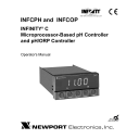
Figure 4-1. Relay Output Triggering Example
OFF ON
ACTIVE ABOVE
OFF
SETPOINT
SIGNAL
LEVEL
ON OFF
ACTIVE BELOW
ON
DEADBAND
SIGNAL
LEVEL
ON OFF
ON
ACTIVE BELOW
WITH DEADBAND 3
ON
NOTE: DEADBAND WORKS AS HYSTERISIS
OFF ON
ACTIVE ABOVE
WITH DEADBAND 3
OFF
3
SETPOINT
3
SIGNAL
LEVEL
ON ON ON
ACTIVE BELOW LATCHED
OFF ON ON
ACTIVE ABOVE LATCHED
Note ☞
To reset latched alarms you must:
1.
Input a signal “OUT” of the Relay Triggering zone
2.
Then press SETPTS and then, RESET button
SETPOINT
28
Configuring The Meter
4
4.10 USING OUTPUT CONFIGURATION (OT.CF)
Use Output Configuration to select the following:
• To enable or disable the analog output
• To determine if the analog output is current or voltage
4.10.1 Enabling or Disabling the Analog Output
To enable or disable the analog output, follow these steps:
1.
Press the MENU button until the meter shows “OT.CF”.
2.
Press the
䊳
T/mV button. The meter shows one of the following:
• “O.1=E” (Analog output enabled) (Default)
• “O.1=D” (Analog output disabled)
3.
Press the 䊱 /pH button to toggle between available choices.
4.
Press the
䊳
T/mV button to select the analog output as current/voltage or press the
MENU button to store your selection. The meter momentarily shows “STRD”, followed by “OT.S.O” (Output Scale and Offset) - refer to section 4.12.
4.10.2 Selecting Analog Output as Current or Voltage
1.
Press the
䊳
T/mV button. The meter shows one of the following:
• “O.2=C" (Analog output = current) (Default)
• “O.2=V” (Analog output = voltage)
2.
Press the
䊱
/pH button to toggle between available choices.
3.
Press the 䊳 T/mV button to go back to selecting analog output as enabled or disabled or press the MENU button to store your choices. The meter momentarily shows “STRD”, followed by “OT.S.O” (Output Scale and Offset) - refer to section
4.12.
29
4
Configuring The Meter
4.10.3 Selecting Analog Output as pH or ORP( for pH/ORP Controllers only)
1.
Press the
䊳
T/mV button. The meter shows one of the following:
• “O.3=P" (Analog Output assigned to pH)
• “O.3=O” (Analog Output assigned to ORP)
2.
Press the
䊱
/pH/ORP button to toggle between available choices.
3.
Press the 䊳 T/mV button to go back to selecting analog output as enabled or disabled or press the MENU button to store your choices. The meter momentarily shows “STRD”, followed by “OT.S.O” (Output Scale and Offset) - refer to section
4.12.
30
Configuring The Meter
4
4.11 CONFIGURING TEMPERATURE (C or F - “TEMP”)
Note
☞
If you have selected “MANU” in “A.T.C.” menu item (Section 4.1), then you have to specify the constant temperature value. Maximum/minimum values are 0 to
199.9 for C or 0 to 398.0 for F.
1.
Press the MENU button until the meter shows “TEMP”.
2.
Press the
䊳
T/mV button. The meter shows actual constant temperature value.
3.
Press the 䊱 /pH button until the first digit is correct.
4.
Press the
䊳
T/mV button to advance to the next digit.
5.
Repeat steps 3 and 4 until meter shows the desired “TEMP” value.
6.
Press the MENU button to store your selection. The meter momentarily shows
“STRD”, followed by “OT.S.O” (Output Scale and Offset) - refer to section 4.12.
7.
Press the MENU button until the meter shows the “CAL.2 or CAL.3” menu.
If the display shows “CAL.2” then proceed to Section 4.4.
If the display shows “CAL.3” then proceed to Section 4.5.
Note ☞
C or F flashes to indicate the unit of measure.
31
4
Configuring The Meter
4.12 USING OUTPUT SCALE AND OFFSET (OT.S.O)
Output Scale and Offset (“OT.S.O”) scales your analog output to be equal to the meter's display and/or any engineering units you require. You may scale the output for direct
(4-20 mA, 0-10 V, etc) or reverse acting (20-4 mA, 10-0 V, etc).
1.
Press the MENU button until the meter shows “OT.S.O”.
2.
Press the
䊳
T/mV button. The meter shows “RD 1” (Read 1).
Note ☞
This is your first point of display reading.
3.
Press the 䊳 T/mV button again. The meter shows the last stored Low pH number with flashing 4th digit.
4.
Press the
䊱
/pH button to change the value of Read 1.
5.
Press the
䊳
T/mV button to scroll to the next digit.
6.
Repeat steps 4 and 5 until the desired value is selected.
7.
Press the MENU button to store your selection. The meter shows “OUT.1” (Output
1) (Low output).
8.
Press the 䊳 T/mV button. The meter shows the selected output.
Note ☞
If you select “O.2=V ” for voltage, the maximum signal you may select is
10.00 for an 0-10 Vdc signal output. If you select “O.2=C” for current, the maximum signal you may select is 20.00 for 0-20 or 4-20 mA dc signal output.
9.
Press the 䊱 /pH button to enter the Output 1 signal selection. If you continue to press the
䊱
/pH button, the flashing digit's value continues to change.
10 Press the 䊳 T/mV button to scroll to the next digit.
11.
Repeat steps 9 and 10 until the desired value is selected.
12.
Press the MENU button to store your selection. The meter shows “RD 2” (Read 2).
Note ☞ This is your second point of display reading.
32
Configuring The Meter
4
4.12 USING OUTPUT SCALE AND OFFSET (OT.S.O) (Continued)
13.
Press the
䊳
T/mV button. The meter shows the last stored High pH number with flashing 4th digit.
14.
Press the
䊱
/pH button to change the value of the flashing digit. If you continue to press the 䊱 /pH button, the flashing digit's value continues to change.
15.
Press the
䊳
T/mV button to scroll to the next digit.
16.
Repeat steps 14 and 15 until the desired value is selected.
17.
Press the MENU button to store your selection. The meter shows “OUT.2”
(Output 2). (High output)
18.
Press the
䊳
T/mV button. The meter shows selected output.
Note ☞
If you select “O.2=V ” for voltage, the maximum signal you may select is
10.00 for an 0-10 Vdc signal output. If you select “O.2=C” for current, the maximum signal you may select is 20.00 for a 0-20 or 4-20 mA dc signal output.
19.
Press the 䊱 /pH button to change the value of the flashing digit. If you continue to press the
䊱
/pH button, the flashing digit's value continues to change.
20.
Press the
䊳
T/mV button to scroll to the next digit.
21.
Repeat steps 19 and 20 until the desired value is selected.
22.
Press the MENU button to store your selection. The meter momentarily shows
“STRD”, then “RST”. The meter will enter into the “RUN” mode (Normal operation).
CAUTION: If the meter displays all flashing values on any item, the value has overflowed. Press the 䊱 /pH button to start new values.
33
4
Configuring The Meter
4.12.1 Example for Output Scale and Offset
You want to send 4-20 mA output for 0 to 14 pH value (default). The meter has 0.01 pH resolution. Complete the following steps:
1.
Press the MENU button until the meter shows “OT.S.O”.
2.
Press the
䊳
T/mV button. The meter shows “RD 1” (Read 1).
3.
Press the 䊳 T/mV button again to show the existing value.
4.
Change the value of “RD 1” to 00.00 by pressing the
䊱
/pH and
䊳
T/mV and buttons.
5.
Press the MENU button to store your selection. The meter shows “OUT.1”
(Output 1).
6.
Press the
䊳
T/mV button again to show the existing value.
7.
Change the value of “OUT.1” to 04.00 by pressing the 䊱 /pH and 䊳 T/mV and buttons.
8.
Press the MENU button to store your selection. The meter shows “RD 2” (Read 2).
9 Press the
䊳
T/mV button to show the existing value.
10.
Change the value of “RD 2” to 14.00 by pressing the
䊱
/pH and
䊳
T/mV buttons.
11.
Press the MENU button to store your selection. The meter shows “OUT.2”
(Output 2).
12.
Press the 䊳 T/mV button to show the existing value.
13.
Change the value of “OUT.2” to 20.00 by pressing the
䊱
/pH and
䊳
T/mV buttons.
14.
Press the MENU button to store your selection. The meter shows “STRD”.
34
Selecting Setpoint Values
5
SECTION 5. SELECTING SETPOINT VALUES
Follow the steps below to select values for Setpoint 1 and Setpoint 2.
1.
Press the SETPTS button. The meter momentarily shows “SP1” (Setpoint 1), followed by the last stored value with flashing 4th digit. The factory default for
“SP1” is 000.0.
2.
Press the
䊱
/pH button to change the value of Setpoint 1.
3.
Press the
䊳
T/mV button to scroll to the next digit.
4.
Press the SETPTS button to store your selection. The meter momentarily shows
“SP2” (Setpoint 2), followed by the last stored value with flashing 4th digit. The factory default for “SP2” is 000.0.
5.
Press the 䊱 /pH button to change the value of Setpoint 2.
6.
Press the
䊳
T/mV button to scroll to the next digit.
7.
Press the SETPTS button to store new values. The meter momentarily shows
“STRD”, “RUN” and then enters the run mode.
Note ☞
You may press the RESET button anytime during this routine to return to the run mode.
35
6
Display Messages
SECTION 6. DISPLAY MESSAGES
Table 6-1. Display Messages
MESSAGE
PH.ER
±LMT
LOCK
UN.LK
CAL.2
CAL.3
TEMP
OFF
RST
A.T.C.
DEC.P
RD.CF
S1.CF
S2.CF
S1.DB
S2.DB
OT.CF
OT.S.O
±OPN
9999
-1999
ER1
VOLT
METR
MANU
SP.RS
SP1
SP2
ER2
DESCRIPTION
Hard (power on) reset
Temperature Compensation Mode
Decimal point
Reading configuration
Setpoint 1 configuration
Setpoint 2 configuration
Setpoint 1 deadband
Setpoint 2 deadband
Output configuration
Output scale and offset
Sensor break or temperature outside range
Value overflow in setpoint/menu peak deviation routines
Value overflow in setpoint/menu peak routines
2 coordinate format programming error
Value Direct from probe in mV
RTD input for A.T.C.
Manually entered input for A.T.C.
Reset setpoints
Setpoint 1 value
Setpoint 2 value
One or more of these items have overflowed due to decimal point change: setpoint values, setpoint deadbands pH value is not accepted
±pH over limit
Lock for RESET, MENU and SETPTS buttons
Unlock for RESET, MENU and SETPTS buttons
Two-point calibration
Three-point calibration
Temperature of solution (A.T.C. - METR) or Temperature configuration (A.T.C. - MANU)
Constant 25ºC input for A.T.C
36
Menu Configuration Displays
7
SECTION 7. MENU CONFIGURATION DISPLAYS
MENU
A.T.C.
Temperature Compensation
Mode
Table 7-1. Configuration Menu
(Defaults in Bold and Italics)
䊳
T/mV
Show A.T.C. choices:
䊱
/pH
METR: Metered - default
MANU: Manually
OFF: Constant 25ºC
DEC.P
Decimal Point
RD.CF
Reading Configuration
S1.CF
Setpoint 1 Configurations
S2.CF
Setpoint 2 Configurations
Show decimal point position
R.2
R.1
FFFF.
FFF.F
FF.FF
C: Celsius
F: Fahrenheit
2: Two-Point Calibration
3: Three-Point Calibration
S.1
S.2
S.1
S.2
A: Active above
B: Active below
U: Unlatched
L: Latched
A: Active above
B: Active below
U: Unlatched
L: Latched
S1.DB
Setpoint 1 Configurations
S2.DB
Setpoint 2 Configurations
CAL.2
Two-Point Calibration
IN 1
Input new value and show “IN 1”
IN 2
Enter new value and show “IN 2”
Scroll right one digit
Scroll right one digit
Show prior and actual value
Show prior and actual value
Change flashing digit’s value
Change flashing digit’s value
37
7
Menu Configuration Displays
SECTION 7. MENU CONFIGURATION DISPLAYS
Table 7-1. Configuration Menu (Continued)
(Defaults in Bold and Italics)
MENU
OT.CF
Output Configuration
䊳
T/mV
0.1
D: Disabled
E: Enabled
䊱 /pH
Analog Output Option 0.2
V: Voltage Analog out
C: Current Analog out
OT.S.O
Output Scale & Offset
Enter new value & show
“OUT1”
Enter new value & show
“RD 2”
Enter new value & show
“OUT2”
TEMP
Temperature Configuration
Show “RD 1” & prior value
Scroll right one digit
Show prior value
Scroll right one digit
Show prior value
Scroll right one digit
Show prior entered value
Scroll right one digit
Change flashing digit’s value
Change flashing digit’s value
Change flashing digit’s value
Change flashing digit’s value
CAL.3
Three-Point Calibration
IN 1
Input new value and show “IN 1”
IN 2
Input new value and show “IN 2”
IN 3
Input new value and show “IN 3”
Show prior and actual value
Show prior and actual value
Show prior and actual value
38
Menu Configuration Displays
7
SECTION 7. MENU CONFIGURATION DISPLAYS
Table 7-2. Run Mode Displays
DISPLAY
TEMP
Temperature
Reading
VOLT mV Reading
SP.RS
䊳 T/mV 䊱 /pH
Shows temperature value of input signal. Press again to show mV value of input signal.
Shows mV value of input signal. Press again to show temperature value of input signal.
RESET Description
LATCHED
RESET
Press RESET button to reset your setpoints.
39
8
Setpoint Configuration Displays
SECTION 8. SETPOINT CONFIGURATION DISPLAYS
Table 8-1. Setpoint Configuration Displays
MENU
SP 1
Setpoint 1
䊳 T/mV
Scroll right one digit
䊱 /pH
Change flashing digit’s value
DESCRIPTION
Select from -1999 through 9999
SP 2
Setpoint 2
Scroll right one digit
Change flashing digit’s value
Select from -1999 through 9999
40
Specifications
9
SECTION 9. SPECIFICATIONS
INPUT SIGNAL
pH and Volt Specification
Range:
Resolution:
- 2.00 to 16.00 pH (-620 to +620 mV)
Accuracy:
Calibration:
From: -200 to -620: 1 mV
± 0.01 pH (± 0.1 mV)
Two or Three Point
Temperature Compensation: Automatic: 0ºC to 100ºC (32ºF to 212ºF)
Manual: 0ºC to 100ºC (32ºF to 212º F)
Note
☞
Volt specification is only used to verify proper operation of electrodes.
)
ORP Specification
Range: -620 to +620 mV
Resolution:
Accuracy:
Note
☞
From: -199.9 to 620.0 mV: 0.1 mV
From: -200 to -620: 1 mV
± 0.1 mV
ORP specification is only used to verify proper operation of electrodes.
TEMPERATURE
Range:
Resolution:
Accuracy:
Unit of Measure:
Sensor:
Isolation:
Noise Rejection:
0ºC to 100ºC (32ºF to 212ºF)
0.1ºC
±0.5ºC
ºF or ºC (programmable by software)
100/1000 Ohm Pt RTD (Connection by phone jack or screw terminals)
Dielectric strength to 2500V transient per 3mm spacing based on EN 61010 for 260Vrms or dc working voltage
Normal Mode Rejection (NMR) = 60dB
Common Mode Rejection (CMR) = 120dB
LED 14-segment, 13.8 mm (0.54”) Display:
Symbol:
Input Impedance: >10 12 ohm
41
9
Specifications
SECTION 9. SPECIFICATIONS (Continued)
ANALOG TO DIGITAL
Technique:
Internal Resolution:
Read Rate:
Dual Slope
15 bits
3 per second for pH; 1 per second for Temperature
RELAY OUTPUTS
2 Form "C" on/off relays. Configurable for latched and unlatched by software.
Max current: 5 A, resistive load
Max voltage: 250 Vac or 30 Vd
ANALOG OUTPUT
Signal Type:
Signal Level:
Function:
Linearity:
Step Response Time:
Current or voltage
Current: 10 V max compliance at 20 mA output
Voltage: 20 mA max for 0-10 V output
May be assigned to a display range or proportional control output with setpoint #1 when used as a control output.
0.2%
2 - 3 seconds to 99% of the final value
ISOLATED ANALOG OUTPUT (TB5, if applicable)
Same as non-isolated analog output except isolated to 1000 Vdc.
Signal Type:
Signal Level:
Function:
Linearity:
Step Response Time:
Current or voltage
Current: 10 V max compliance at 20 mA output
Voltage: 20 mA max for 0-10 V output
May be assigned to a display range or proportional control output with setpoint #1 when used as a control output.
0.2%
2 - 3 seconds to 99% of the final value
Note
☞
Only one analog output is available on each unit and it must be factory installed.
42
Specifications
9
SECTION 9. SPECIFICATIONS (Continued)
INPUT POWER INFORMATION
~ AC units 115/230 V~(AC) ±10%, 50/60 Hz
7 W max, power consumption (Non-Isolated Analog Output)
8 W max, power consumption (Isolated Analog Output)
DC units 10-32 Vdc
6 W max, power consumption (Non-Isolated Analog Output)
7 W max, power consumption (Isolated Analog Output)
External Fuse Protection Recommended:
IEC 127-2/III
Power
115 V
Fuse
125 mA @ 250 (T)
230 V 63 mA @ 250 (T)
UL 248-14 (Listed Fuse)
Power Fuse
115 V
230 V
175 mA @ 250 V Slow-Blow
80 mA @ 250 V Slow-Blow
ENVIRONMENT
Operating temperature:
Storage temperature:
Relative humidity:
0° to 50°C (32° to 122°F)
-40° to 85°C (-40° to 185° F)
90% at 40°C (non-condensing)
MECHANICAL
Panel cutout:
Weight:
Case material:
1/8 DIN 3.62 x 1.78" (45 x 92mm)
1.27 lb (575 g)
Polycarbonate, 94 V-O UL rated
43
9
Specifications
SECTION 9. SPECIFICATIONS (Continued)
48,00 (1.890) 96,00 (3.780)
17,78 (.700)
CASE
REAR
COVER
SIDE VIEW TOP VIEW
PANEL THICKNESS
6,4 (.25) MAX
0,8 (.03) MIN
1,5
R(.06)
4 PLCS
45,00 + 0,61/-0,00
(1.772 + .024/–.000)
92,00 + 0,81/–0,00
(3.622 + .032/–.000)
NOTE: Dimensions in Millimeters (Inches)
Figure 9-1. Dimensions/ Panel Cutout
Figure 9-1
44
Factory Preset Values
10
SECTION 10. FACTORY PRESET VALUES
Table 10-1. Factory Preset Values
MENU ITEM FACTORY PRESET VALUES
A.T.C.
DEC.P
RD.S.O
RD.CF
S1.CF
S2.CF
S1.DB
S2.DB
OT.CF
OT.S.O
SP1
SP2
TEMP
Temperature Compensation: METR
Decimal Point Position: FFF.F
Reading Scale and Offset:
4-20 mA dc = 0-1000
Reading Configuration:
R.1=3 (3 Point Calibration)
R.2=C (Degree Celsius)
Setpoint 1 Configuration:
S.1=A (Setpoint is active above)
S.2=U (Setpoint is unlatched)
Setpoint 2 Configuration:
S.1=A (Setpoint is active above)
S.2=U (Setpoint is unlatched)
Setpoint 1 Deadband: 0003
Setpoint 2 Deadband: 0003
Output Configuration:
O.1=E (Analog output is enabled)
O.2=C (Analog output is current)
Output Scale and Offset:
0-14 pH = 4-20 mA
Setpoint 1 Value: 0000
Setpoint 2 Value: 0000
Temperature Compensation value set to 025.0
45
46
CE APPROVAL INFORMATION
1. Electromagnetic Compatibility (EMC)
This device comforms with requirements of EMC Directive 89/336/EEC, amended by 93/68/EEC. This instrument complies with the following EMC
Immunity Standards as tested per EN 50082-2, 1995 (Industrial environment)
Phenomena
Electrostatic
Discharge
Radio Frequency electromagnetic field.
Test Specification
+/- 4 kV contact discharge
+/- 8 kV air discharge
27 - 1000 MHz
10 V/m
80% AM (1 KHz)
Basic Standard
IEC 1000-4-2
Performance
Criteria B
IEC 1000-4-3
Performance
Criteria A
Radio Frequency 900 MHz electromagnetic field.
10 V/m
Pulse modulated.
50% Duty cycle @ 200 Hz
Fast Transients +/- 2 kV (ac mains)
+/- 1 kV (dc, signal I/O)
IEC 1000-4-3
Performance
Criteria A
IEC 1000-4-4
Performance
5/50 ns Tr/Th, 5 KHz rep. freq.
Criteria B
Radio Frequency conducted
0.15 - 80 MHz
10 V/m
80% AM (1 KHz)
IEC 1000-4-6
Performance
Criteria A
This instrument complies with the following EMC Emission Standards as tested per EN 50081-1, 1992 (Residential, Commercial and Light Industrial)
Phenomena
Radiated
Emission
Conducted
Emission
Frequency
Range
30-230 MHz
230-1000 MHz
0.15-0.5 MHz
0.5-5 MHz
5-30 MHz
Limits
30 dB_V/m at 10 m
37 dB_V/m at 10 m quasi peak
66-56 dB_V quasi peak
56 dB_V quasi peak
60 dB_V quasi peak
Basic
Standard
CISPR 22
Class B
CISPR 22
Class B
2.Safety
This device conforms with Low Voltage Directive 73/23/EEC, amended by 93/68/EEC.
The following LVD requirements have been met to comply with EN 61010-1, 1993
(Electrical equipment for measurement, control and laboratory use)
1. Pollution Degree 2
2. Installation Category II
3. Double Insulation
4. Class I Equipment (Units with 115/230 Vac power)
Class III Equipment (Units with 10-32 Vdc power)
Warranty/Disclaimer
NEWPORT Electronics, Inc. warrants this unit to be free of defects in materials and workmanship for a period of one (1) year from the date of purchase. In addition to NEWPORT’s standard warranty period, NEWPORT Electronics will extend the warranty period for one (1) additional year if the warranty card enclosed with each instrument is returned to
NEWPORT.
If the unit should malfunction, it must be returned to the factory for evaluation. NEWPORT’s Customer Service
Department will issue an Authorized Return (AR) number immediately upon phone or written request. Upon examination by NEWPORT, if the unit is found to be defective it will be repaired or replaced at no charge. NEWPORT’s WARRANTY does not apply to defects resulting from any action of the purchaser, including but not limited to mishandling, improper interfacing, operation outside of design limits, improper repair, or unauthorized modification. This WARRANTY is VOID if the unit shows evidence of having been tampered with or shows evidence of being damaged as a result of excessive corrosion; or current, heat, moisture or vibration; improper specification; misapplication; misuse or other operating conditions outside of NEWPORT’s control. Components which wear are not warranted, including but not limited to contact points, fuses, and triacs.
NEWPORT is pleased to offer suggestions on the use of its various products. However, NEWPORT neither assumes responsibility for any omissions or errors nor assumes liability for any damages that result from the use of its products in accordance with information provided by NEWPORT, either verbal or written. NEWPORT warrants only that the parts manufactured by it will be as specified and free of defects. NEWPORT MAKES NO
OTHER WARRANTIES OR REPRESENTATIONS OF ANY KIND WHATSOEVER, EXPRESSED OR IMPLIED,
EXCEPT THAT OF TITLE, AND ALL IMPLIED WARRANTIES INCLUDING ANY WARRANTY OF
MERCHANTABILITY AND FITNESS FOR A PARTICULAR PURPOSE ARE HEREBY DISCLAIMED. LIMITATION OF
LIABILITY: The remedies of purchaser set forth herein are exclusive and the total liability of NEWPORT with respect to this order, whether based on contract, warranty, negligence, indemnification, strict liability or otherwise, shall not exceed the purchase price of the component upon which liability is based. In no event shall
NEWPORT be liable for consequential, incidental or special damages.
CONDITIONS: Equipment sold by NEWPORT is not intended to be used, nor shall it be used: (1) as a “Basic
Component” under 10 CFR 21 (NRC), used in or with any nuclear installation or activity; or (2) in medical applications or used on humans. Should any Product(s) be used in or with any nuclear installation or activity, medical application, or used on humans, or misused in any way, NEWPORT assumes no responsibility as set forth in our basic WARRANTY /
DISCLAIMER language, and additionally purchaser will indemnify NEWPORT and hold NEWPORT harmless from any liability or damage whatsoever arising out of the use of the Product(s) in such a manner.
Return Requests/Inquiries
Direct all warranty and repair requests/inquiries to the NEWPORT Customer Service Department.
BEFORE RETURNING ANY PRODUCT(S) TO NEWPORT, PURCHASER MUST OBTAIN AN
AUTHORIZED RETURN (AR) NUMBER FROM NEWPORT’S CUSTOMER SERVICE DEPARTMENT
(IN ORDER TO AVOID PROCESSING DELAYS). The assigned AR number should then be marked on the outside of the return package and on any correspondence.
The purchaser is responsible for shipping charges, freight, insurance and proper packaging to prevent breakage in transit.
FOR WARRANTY RETURNS, please have the following information available BEFORE contacting NEWPORT:
1.
P.O. number under which the product was
PURCHASED,
2.
Model and serial number of the product under warranty, and
3.
Repair instructions and/or specific problems relative to the product.
FOR NON-WARRANTY REPAIRS, consult
NEWPORT for current repair charges. Have the following information available BEFORE contacting NEWPORT:
1.
P.O. number to cover the COST of the repair,
2.
Model and serial number of product, and
3.
Repair instructions and/or specific problems relative to the product.
NEWPORT’s policy is to make running changes, not model changes, whenever an improvement is possible. This affords our customers the latest in technology and engineering.
NEWPORT is a registered trademark of NEWPORT ELECTRONICS, INC.
© Copyright 2001 NEWPORT ELECTRONICS, INC. All rights reserved. This document may not be copied, photocopied, reproduced, translated, or reduced to any electronic medium or machine-readable form, in whole or in part, without prior written consent of NEWPORT ELECTRONICS, INC.
M1570/N/0801
For immediate technical or application assistance please call:
®
Newport Electronics, Inc.
2229 South Yale Street • Santa Ana, CA • 92704 • U.S.A.
TEL: (714) 540-4914 • FAX: (714) 546-3022
Toll Free: 1-800-639-7678 • http://www.newportUS.com • e-mail:[email protected]
ISO 9001 Certified
Newport Technologies, Inc.
976 Bergar • Laval (Quebec) • H7L 5A1 • Canada
TEL: (514) 335-3183 • FAX: (514) 856-6886
Toll Free: 1-800-639-7678 • http://www.newport.ca • e-mail:[email protected]
Newport Electronics, Ltd.
One Omega Drive • River Bend Technology Centre
Northbank, Irlam • Manchester M44 5BD • United Kingdom
Tel: +44 161 777 6611 • FAX: +44 161 777 6622
Toll Free: 0800 488 488 • http://www.newportuk.co.uk • e-mail:[email protected]
Newport Electronics B.V.
Postbus 8034 • 1180 LA Amstelveen • The Netherlands
TEL: +31 20 3472121 • FAX: +31 20 6434643
Toll Free: 0800 0993344 • http://www.newport.nl • e-mail: [email protected]
Newport Electronics spol s.r.o.
Rudé armády 1868, 733 01 Karviná 8 • Czech Republic
TEL: +420 69 6311899 • FAX: +420 69 6311114
Toll Free: 0800-1-66342 • http://www.newport.cz • e-mail: [email protected]
Newport Electronics GmbH
Daimlerstrasse 26 • D-75392 Deckenpfronn • Germany
TEL: 49 7056 9398-0 • FAX: 49 7056 9398-29
Toll Free: 0800 / 6397678 • http://www.newport.de • e-mail: [email protected]
Newport Electronique S.A.R.L.
9, rue Denis Papin • 78190 Trappes • France
TEL: +33 130 621 400 • FAX: +33 130 699 120
Toll Free: 0800-4-06342 • http://www.newport.fr • e-mail: [email protected]
Mexico and Latin America
TEL: 001-800-826-6342 • FAX: 001 (203) 359-7807
En Español: 001 (203) 359-7803
11799ML-04 Rev. A
advertisement
* Your assessment is very important for improving the workof artificial intelligence, which forms the content of this project