advertisement

15 SWITCHING THE MODE AFTER STARTING
MELSEC-Q
15.5 Switching the Mode from an External Device
This section shows how the Q series C24 mode is switched from an external device.
15.5.1 Mode switching procedure
External device
PLC CPU
Mode switching in progress
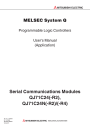
The following explains the procedure for switching the Q series C24 mode from an external device.
1
Mode switching command message
See Section 3.13 of reference manual for message format
Mode switching response message
(Normal end)
Approx. 400 ms
X6/XD
2
CH ERR. communication error
XE/XF
Q series C24 ready
X1E
Switch setting error, mode switching error strage area (address 203
H
)
Buffer memory special applications area
Data communications initialization setitng area described in
Section 3.9 of User's Manual (Basic).
Addresses 93
H
to 121
H
/133
H
to 1C1
H
Data communications possible
3
FROM
(Only when normal)
3
TO
Data communications impossible default value modification
(Performed only when necessary)
4 Data communications possible
1 Inform in advance all the connected devices that data communications by mode switching cannot be performed.
2 When XE, XF was turned on, check the error contents described in Sections
10.1.2 and 10.1.5 of User’s Manual (Basic) and take the corresponding action.
• Checking of mode switching designation contents for buffer memory mode switching area and writing of mode switching designation contents within the range that can be designated.
• Re-execution of mode switching
3 When the mode was switched from an external device, after mode switching is complete, read and write the buffer memory special applications area shown below from the PLC CPU.
• Switch setting error, mode switching error storage area (address: 203
H
)
• Data communications initialization setting areas (addresses: 93
H
to
121
H
/133
H
to 1C1
H
) described in Section 3.9 of User's Manual (Basic).
4 After checking that mode switching was completed normally, inform all the connected devices that data communications are possible and restart data communications.
15 - 9 15 - 9
15 SWITCHING THE MODE AFTER STARTING
MELSEC-Q
REMARK
To check the Q series C24 mode (communication protocol, transmission specifications) after switching, read the buffer memory (addresses: 252
H
to 253
H
,
262
H
to 263
H
) described in Section 10.1.5 of User's Manual (Basic).
(To check the external device, read the buffer memory with the MC protocol buffer memory read function.)
15.5.2 Mode switching sample program
The following shows a PLC CPU sample sequence program that switches the CH1 interface mode from an external device.
(The Q series C24 I/O signals X/Y00 to X/Y1F)
Remodification of setting value of buffer memory special applications area
Reads the mode switching error contents.
Mode switching complete.
Changes the setting value of the communication protocol accoding to the communication specification.
Mode switching complete reset.
Error processing (LED OFF, error code clear)
15 - 10 15 - 10
advertisement
* Your assessment is very important for improving the workof artificial intelligence, which forms the content of this project