advertisement

2
HP PCL-II
Introduction
This chapter describes the HP ® PCL-II emulation host control codes that are supported for your LineJet printer. Emulation refers to the ability of a printer to execute the commands of a particular printer control language. A printer control language is the coding system used to convey, manipulate, and print data. It contains character codes and command sequences that configure the emulation. In this manual, the terms emulation, printer protocol, and printer control language are synonymous.
In the HP PCL-II emulation mode, your printer can print files coded for the HP
PCL-II printer control language. To select the PCL-II emulation mode as the active printer emulation, select PCL-II in the ACTIVE EMULATION menu and then the PCL-II menu will appear under the EMULATION menu, as described in the LineJet Printers: User’s Guide .
The PCL-II emulation provides many configurable parameters. The default parameter values for this emulation are shown in Table 2. You can modify the emulation parameter values in two ways:
• The PCL-II host control codes. An extensive set of PCL-II control code commands can be sent to the printer from an attached host computer via the host data stream. Most of this chapter is devoted to describing the
PCL-II control code commands.
• The printer configuration menus. You can modify a subset of the PCL-II emulation parameters using the printer configuration menus and control panel keys as described in the LineJet Printers: User’s Guide .
A parameter value set by a host control code overrides a value set from the printer’s control panel.
Note Configuration values selected from the menus or via host control codes can be saved to memory so that they will not be lost when you power off the printer. The menu selection for saving a configuration to memory is described in the
LineJet Printers: User’s Guide.
27
Chapter 2 Introduction
HP PCL-II Emulation Default Settings
The factory settings for the PCL-II emulation menu options are shown in
Table 2. Host control codes can override the settings for these menu options.
Table 2. PCL-II Menu Option Factory Settings
Default Setting Parameter
Primary/Secondary Character Set
ID
Symbol Set
Pitch
Density
Page Length Representation
Graphics Density
Perforation Skip
Display Functions
LF after CR
CR after LF
CR after FF
CR after VT
PTX Linefeed
LPI Adjust
Page L. /Lines
Page L. /Inches
0
Roman-8(8U)
10.0 cpi
Data Processing
Inches/Page
60 dpi
Disable
Disable
Disable
Disable
Disable
Enable
Disable
6 LPI
66 lines
11 Inches
Switching Between the Emulations
The printer supports four emulations: PCL-II (the default), LinePrinter Plus ® ,
Code V™ and IGP/PGL. The LinePrinter Plus has three protocols from which to choose: P-Series, Proprinter III XL, and Epson FX-1050.
You can switch between PCL-II and any of the LinePrinter Plus protocols by sending one of the following commands:
ESC%-00000X
ESC%-00001X
ESC%-00002X
SFCC|};K0
Switches from PCL-II to P-Series
Switches from PCL-II to Proprinter III XL
Switches from PCL-II to Epson FX-1050
Switches from any of the LinePrinter Plus emulations to PCL-II
28
Printer Feature Set Compatibility
Note The SFCC is the Special Function Control Code. From the
P-Series protocol, this code is selectable from the front panel. The default value is hex 01. For the Proprinter and
Epson emulations, the SFCC is always the ESC (hex 1B) character.
Configuring the PCL-II Emulation with Control Codes
The remainder of this chapter describes the PCL-II printer control language codes that may be sent from a host computer attached to the printer.
The escape (ESC) control code is used to select most of the programmable features.
Commands and control codes sent from a host system override settings in the configuration menus. However, any configuration settings from host control codes will be gone once the printer is powered off (or reset to the default values). Host control codes are never reflected in the PCL-II configuration menu. In order to save a configuration, it is necessary to select the desired options from the front panel and save the options to one of the printers eight user-selectable configurations. The LineJet Printers: User’s Guide describes the menu option for saving changes to the printer memory.
Printer Feature Set Compatibility
The printer uses the “Printer Control Language” which standardizes printer features and user access of these features, providing compatibility between
HP printers. “Printer Control Language” structure consists of five feature levels:
• Level I
• Level II
Print and Space
EDP
• Level III
• Level IV
• Level V
Word Processing
Page Formatting
Enhanced Page Formatting
Each PCL level supersedes features of the levels below it. The LineJet printers are Level II printers, meaning that all applications for Level I and II printers will operate correctly on your printer with no modifications. In addition to supporting Level I and Level II features, the printer supports a limited set of additional features that may not be supported by other HP products.
Applications written using these additional features may not operate as intended on other Hewlett-Packard printers which do not have these capabilities.
29
Chapter 2 Configuring the PCL-II Emulation with Control Codes
General Information
Programmatic Printer Control
Control codes, multi-character escape sequences, and parameterized escape sequences are all used to control the printers.
The printers execute parameters sequentially, in the order they are received.
Therefore, the order of the parameters is significant. Unrecognized escape sequences are ignored in their entirety and may cause erroneous printing since the printer may be unable to perform the requested operation.
Logical and Physical Pages
The limits of the logical page determine the area in which printing can take place. Logical page length is set programmatically (in lines per page).
Physical page length is set via the control panel and indicates the actual size of a single page. The physical page length cannot be changed programmatically. Refer to the LineJet Printers: Quick Reference Guide for more information.
Function
Backspace
Horizontal
Tab
Line Feed
Form Feed
Carriage
Return
Shift Out
Symbol
BS
HT
LF
FF
CR
Table 3. Control Codes
Binary Level
1000
1001
II
V
1010
1100
1101 I
I
I
Description
Move one column left.
Move the current active position to the next tab stop on the current line. The tab stops are at the left margin and every 8th column between the left and right margins. If new position crosses the right margin, the new position is set to the right margin.
Move to next print line while maintaining current column position
Move to first line at top of the next page while maintaining current column position
Move to the left margin on current print line
SO 1110 I
Shift In SI
Escape ESC
1111
11011
I
I
Select following characters from the current secondary character font until receipt of a
Shift In
Select following characters from the current primary character font until receipt of a Shift
Out
The following characters are a special control sequence
30
Escape Sequences
Escape Sequences
An escape sequence consists of the ESC control code followed by one or more characters in succession. Both two-character and parameterized escape sequences control the printer. Two-character escape sequences take the form ESCX, where X is a character from the ASCII table (0 through ~).
Parameterized escape sequences are structured in the following form:
ESCXy[parameter]Z
This sequence is explained below:
ESCXy Prefix. This part of the escape sequence indicates that the escape sequence is parameterized and also specifies which type of control is being performed. “X” is referred to as the parameterized character; “y” is referred to as the group character.
Parameter This string of ASCII characters specifies a value (either numeric or alphanumeric).
Z Terminator. This ASCII character indicates the function to which the previous parameter value applies. If this character is lower case (a,b,c, etc.), it indicates a combined escape sequence, meaning that more parameterized information will follow. If the character is upper case (A,B,C, etc.), it terminates the escape sequence string.
Note Brackets [ ] are shown in many of the escape sequences for clarification purposes, but are not actually part of the escape sequence. For example, the brackets in the escape sequence for selecting page length (ESC&l[1-128]P) specify a range of values (1 through 128) for page length. To specify a page length of 35 lines, the escape sequence ESC&l35P would be sent to the printer.
Combining Escape Sequences
Parameterized escape sequences can be combined to save keystrokes.
Combining sequences involves adding the parameter value and terminator of one or more sequences to another escape sequence. Parameterized sequences can be combined only if their prefixes are identical. When a parameter/terminator of one sequence is added to another sequence, all of the terminators except the last should be lower case. For example, to set the left and right margins using two separate escape sequences, the following two sequences would be sent:
Set left margin at position 10
Set right margin at position 99
ESC&a10L
ESC&a99M
Using one combined escape sequence, the following would be sent to the printer:
ESC&a10l99M
31
Chapter 2 Configuring the PCL-II Emulation with Control Codes
The list below shows the escape sequences you can use with the printer.
Note that the brackets [ ] used in these escape sequences are for clarification purposes only (the brackets are not actually part of the commands).
FUNCTION
PCL LEVEL I
ASCII CODE PAGE
Display Functions Mode on
Display Functions Mode off
Perforation Skip Mode on
Perforation Skip Mode off
Raster Graphics end
Self-test
Stroke Weight (Bold)
Underline Mode on
Underline Mode off
ESCY
ESCZ
ESC&l1L
ESC&l0L
Print Mode Selection (10 & 16.67 cpi) ESC&l[0,2]S
Programmable reset ESCE
Raster Graphics start
Raster Graphics data
ESC*rA
ESC*b[#]W[ data ]
ESC*rB
ESCz
69
71
ESC[(,)]s[#]B 71
ESC&d[DEFGLMNOTUVW\}^] 72
ESC&d[@CHIJKPQRSWXZ[] 72
58
60
69
69
55
55
57
57
PCL LEVEL II
Character Font Selection
Cursor Control (absolute row)
Cursor Control (absolute column)
Cursor Control (relative row)
Cursor Control (relative column)
Horizontal Margin Selection (Left)
PCL LEVEL III
ESC[(,)] ID
ESC&a[#]R
ESC&a[#]C
ESC&a[+#]R
ESC&a[+/-#]C
ESC&a[ print position ]L
Horizontal Margin Selection (Right) ESC&a[
Horizontal Margin Selection (Reset) ESC9 print position ]M
Line Spacing
Logical Page Length Selection
ESC&l[6,8]D
ESC&l[1-128]P
Print Pitch Selection ESC[(,)]s[ Cpi ]H
Text Length (Vertical Margin) Selection ESC&l[1-128]F
Transparent Print Data ESC&p[ # of bytes ]X
54
55
55
55
50
54
54
54
56
56
58
72
72
Character Density Selection
Character Style Selection
Print Mode Selection (12 cpi)
ESC[(,)]s[0,1,-1]Q
ESC[(,)]s[0,1]S
ESC&l4S
47
53
58
32
Escape Sequences
Additional Commands
Bar Code Data
Bar Code Height
Bar Code Header Control
Bar Code Label Placement
Bar Code Selection
Emulation Switching
Print Mode Selection (double size)
PTX Linefeed
ESC*z[< bar code data> ]Z
ESC*z[#]H
ESC*z[#]Q
ESC*z[#]C
ESC*z[#]V
ESC%-[0000,0001,0002]X
ESC&l8S
ESC*t[0,1]L
Programmable VFC ESC&l[ #bytes ]W[ data ]
Raster Graphics: Move # raster lines ESC*b[#]Y
Raster Graphics: Resolution ESC*t[70,140]R
Raster Graphics: Horizontal ResolutionESC*r[60,70,120,140]L
Raster Graphics: Vertical Resolution ESC*r[72,144]V
Standard (Computed) VFC ESC&l[0-16]V
60
69
69
69
69
73
34
28
58
59
34
34
34
34
33
Chapter 2 Configuring the PCL-II Emulation with Control Codes
Bar Codes
To print bar codes, escape sequences are sent to the printer specifying the type of code, bar code height, bar code header information, placement information, and bar code data. The following five escape sequences are used for bar code printing:
ESC*z#V Bar Code Selection
This sequence selects the type of bar code to be used in subsequent printing of bar code data. If a number other than those available is selected, the previously selected bar code type will be used. The following table lists the bar code types available and their corresponding value field numbers.
Table 4. Bar Code Types
Bar Code Type
Code 3 of 9 (default)
Industrial 2 of 5
Interleaved 2 of 5
UPC A
UPC E
EAN 8
EAN 13
UCC/EAN-128
Postnet
Royal Mail (including KIX format)
Character Length
Variable
Variable
Variable
Fixed
Fixed
Fixed
Fixed
Fixed
Fixed
Variable
Value Field No.
9
10
11
12
4
8
0
1
13, 14
15, 16
Note The Postnet Barcodes type 13 & 14 print 24 bars per inch.
See the section on 256x Postal Barcodes for information on the 20 bars per inch and 22.5 bars per inch Postal Barcodes.
ESC*z#H Bar Code Height
This escape sequence defines the height of the bar code label in tenths of an inch as specified in the value field (#). To specify a bar code height of .8 inches, the ESC*z8H escape sequence would be sent to the printer. A zero in the value field specifies that bar code height is determined by the current line spacing (1/6 or 1/8 inch for 6/8 LPI respectively, or 1/3 or 1/4 inch for doublehigh/double-wide). The default bar code height is 0.6 inches.
34
Bar Codes
ESC*z#C Bar Code Label Placement
This escape sequence specifies the horizontal starting location of a bar code by specifying the column number based on the currently active print pitch.
The value field (#) indicates the absolute column position the bar code will begin printing. A plus or minus sign in the value field is ignored. A value field whose position is less than the current active printing position is illegal and causes the cursor to move to the next column position to the right of the current active printing position. When printing bar codes, always allow at least
1/4 inch margin in all directions from each bar code. This will limit the interference from other characters and help readability. If you need to print text and bar codes on the same line, see the “Printing Bar Codes With Text” discussion later in this chapter.
ESC*z#Q Bar Code Header Control
This sequence specifies the placement of the bar code header. A number 1 in the value field specifies that a header will be printed above the bar code label and a 2 specifies that it will be placed below the bar code. A zero in the value field specifies that no header will be printed. The printer default places the header above the bar code.
ESC*z<Bar Code Data>Z Bar Code Label Data
This sequence sends the bar code label data in the form of an alphanumeric string enclosed in angled brackets. The header (if enabled) will print in the location specified by the bar code header control sequence.
Note Upon termination of the bar code label data escape sequence, the printer will print all buffered bar code data and generate a carriage return.
The printer automatically formats the bar code, inserts start and stop bits, and calculates and inserts the checksum (if applicable-not for Code 3 of 9,
Industrial 2 of 5, or Interleaved 2 of 5 ).
For UPC E bar codes, a zero (0) must be in the first position of the bar code data.
35
Chapter 2 Configuring the PCL-II Emulation with Control Codes
Printing Bar Codes
Generally, sending bar code information to the printer is performed in two steps:
Step 1: Selecting the bar code printing specifications; bar code type, height, and header control information.
Step 2: Moving the cursor to the desired label location and sending the bar code data.
Step 1.
Before positioning and printing the bar code data, the type of code, height of the label, and header placement may be specified. Once this is done, the succeeding labels will be printed using these specifications until a new type, height, or header control is specified. In other words, the bar code print specifications can be sent once and need not be sent again unless the printer is reset or new print specifications are desired. The following example specifies the print specifications for bar codes that are 0.5 inches in height, have a header above the label, and are printed in the UPC A code.
ESC*z8v5h1Q
ESC*z8v Select UPC A code
5h Label is to be .5 inches high
1Q Places header above bar code
Notice that the last letter in the escape sequence (Q) is upper-case while the other letters in the sequence (v and h) are lower-case. (See “Escape
Sequences” on page 31 for more information concerning combining two or more sequences.)
Step 2.
To print a bar code label, the cursor must be placed in the desired position and the bar code data must be sent. The following escape sequence moves the cursor to column 25, sends the data “1234567” to the printer, and initiates printing.
ESC*z25c<1234567>Z
ESC*z25c Places start of label at column 25
< Indicates start of bar code data
1234567 Bar code data
> Signals end of bar code data
Z Upper case Z initiates printing *
*Note that an upper-case “Z” terminator results in the bar code being printed and an automatic carriage return (CR) being executed.
36
Bar Codes
Printing Multiple Labels On The Same Line
Printing more than one label on the same line involves no more than positioning the cursor and sending the data for each label to be printed. Since the termination of the bar code data sequence (signalled by an upper-case Z) causes the bar code to be printed and a carriage return to be executed, all of the label information must be sent in the same escape sequence. The following example shows an escape sequence used to print three labels on a single line:
ESC*z5c<label1>z20c<label2>z35c<label3>Z
ESC*z5c Moves cursor to column 5
<label1> Bar code data z20c Moves cursor to column 20
<label2> Bar code data z35c Moves cursor to column 35
<label3> Bar code data
Z Initiates printing
Printing Bar Codes With Text
When printing bar codes with text, since the printer automatically generates a carriage return and line feed at the end of the terminating character (upper case Z), potential problems exist. As a general rule, for each line of bar code mixed with text, send the text information first, followed by a carriage return without a line feed (ASCII 13), and then overlay the bar code. (The carriage return is required so that the bar code cursor position will be correct.) The following example illustrates how to print text and bar codes on the same line.
This example involves a three-line bar code (and three escape sequences) as shown below:
ESC*z0v25c1q<12345>Z
ESC*z0v Selects Code 3 of 9
25c Moves cursor to column 25
1q Specifies header placement above label
<12345> Bar code data
Z Enables printing this portion of the bar code
ESC*z75CThis is textCRESC*z0q25c<12345>Z
ESC*z75C Moves cursor to column 75
This is text Text for right of bar code
CR Carriage return without a line feed
ESC*z0q Disables header for this portion
25c Moves cursor to column 25
<12345> Bar code data
Z Initiates printing this portion
ESC*z25c0q<12345>Z
ESC*z25c Moves cursor to column 25
0q Disables header for lower portion
<12345> Bar code data
Z Initiates printing for lower portion of label
37
Chapter 2 Configuring the PCL-II Emulation with Control Codes
Note When a header is enabled, sending one line of information causes the printer to print two lines; one line containing the header along with any text you may have sent in that line, and one line containing the bar code label. When a header is enabled, no information can be printed on the same line as the bar code label. However, if the header is disabled, text can be placed next to the bar code label. For example, if you want a label and also wish to enclose the bar code with a box, you may not use automatic headers. Instead, you may set the height of the bar code to the text height and manually print the header.
Bar Code Width Information
The following paragraphs contain information concerning the size of the printed bar codes. If you are designing a form that contains bar codes, this information may prove useful in judging how much space the bar code will occupy.
The following table lists the number of characters sent by the user for each type of bar code:
Table 5. Bar Code Character
Bar Code Number of Characters Sent
Code 3 of 9
Industrial 2 of 5
Interleaved 2 of 5
UPCA
UPCE
EAN8
EAN13
UCC/EAN-128
Variable
Variable
Variable
11
11
7
12
19
Postnet 5 (6), 9(10), or 11(12)
Royal Mail (incl. KIX) Variable
Note For Postnet Barcodes printed using the LineJet style, if 5, 9, or 11 digits are sent, your printer will automatically calculate and print the check digit. If 6, 10, or 12 digits are sent, the printer will verify the check digit. Should the check digit be inaccurate, or an invalid bar code length is sent, your LineJet printer will not attempt to print the invalid data.
38
Bar Codes
CODE 3 OF 9
A variable-length data string of up to 32 ASCII characters may be printed using the Code 3 of 9 bar code. The string may be an odd or even length and may use any of the standard characters (specified in MIL-STD-1189). If a non-valid character is used in the string, a blank non-readable bar code will be printed; non-valid characters are not substituted or deleted. The width of the printed bar code can be approximated by the following equation:
Width in inches = (number of characters)/3.14 + 0.50
INDUSTRIAL 2 OF 5
A variable-length data string of up to 32 ASCII characters may be printed using the Industrial 2 of 5 bar code. The string may be an odd or even length and may use any character from 0 through 9. If a non-valid character is used in the string, a blank non-readable bar code will be printed; non-valid characters are not substituted or deleted. Optional checksums are not inserted in the bar code. The width of the printed bar code can be approximated by the following equation:
Width in inches = (number of characters)/3.7 + 0.38
INTERLEAVED 2 OF 5
A variable-length data string of up to 32 ASCII characters may be printed using the Interleaved 2 of 5 bar code. The string may be an odd or even length. However, if the string is an odd length, a leading zero will be inserted to make a string of an even length. Valid data characters are 0 through 9. If a non-valid character is used in the string, a blank non-readable bar code will be printed; non-valid characters are not substituted or deleted. Optional checksums are not inserted in the bar code. The width of the printed bar code can be approximated by the following equations:
Width in inches = (even number of characters)/6.25 + 0.15
UPCA
A fixed-length data string of 11 ASCII characters may be printed using the
UPC A bar code. The string must have a length of 11 and may use any of the standard characters 0 through 9. If a non-valid character or string length is used, a blank non-readable bar code will be printed; non-valid characters are not substituted or deleted. The width of the printed bar code does not vary and is 1.56 inches.
UPCE
A fixed-length data string of 11 ASCII characters may be printed using the
UPC E bar code. The string length must be 11 and may use any of the standard characters 0 through 9 (however, the data pattern must meet the format of UPC E bar codes; UPC E is a shortened version of very specific patterns printable with UPC A). If a non-valid character or string length is used, a blank non-readable bar code will be printed; non-valid characters are not substituted or deleted. For UPC E, a zero (0) is required in the first position of the bar code data (the number system character). The width of the printed bar code is not variable and is 0.81 inches.
39
Chapter 2 Configuring the PCL-II Emulation with Control Codes
EAN8
A fixed-length data string of 7 ASCII characters may be printed using the EAN
8 bar code. The string length must be 7 and may use any of the standard characters 0 through 9. If a non-valid character or string length is used, a blank non-readable bar code will be printed; non-valid characters are not substituted or deleted. The width of the printed bar code is not variable and is
1.25 inches.
EAN13
A fixed-length data string of 12 ASCII characters may be printed using the
EAN 13 bar code. The string length must be 12 and may use any of the standard characters 0 through 9. If a non-valid character or string length is used, a blank non-readable bar code will be printed; non-valid characters are not substituted or deleted. The width of the printed bar code is not variable and is 1.56 inches.
Royal Mail
A variable length data string may be printed using the “Royal Mail 4 State
Customer Code”. The string may use any character from 0 through 9 and alpha characters A through Z. A complete bar code consists of a set of distinct bars and spaces for each character followed by a checksum character and enclosed by a unique start bar, stop bar and quiet zone. A second version of the Royal Mail barcode prints with no stop bar, start bar or checksum character.
The KIX format for Royal Mail does not include the start/stop code or the check digit, but will allow lowercase alpha characters a through z.
UCC/EAN 128
The UCC/EAN-128 bar code contains special characters which use unique codes to identify the leading and trailing end of the bar code. EAN/UCC 128 supports a full ASCII character set and provides standard alphanumeric keyboard characters and control and special characters.
The EAN/UCC 128 data structure requires an Application Identifier (AI) at the beginning of barcode data. Each AI determines the format and length of the data which follows. Refer to Table 6 for more detail.
Table 6. UCC/EAN-128 Application Identifiers
Application
Identifier (AI)
00
02
10
11 (*)
13 (*)
Content
Serial Shipping Container Code
Item Num. of Goods Within Another Unit
Batch or Lot Number
Production Date (YYMMDD)
Packaging Date (YYMMDD)
Format n2+n18 n2+n14 n2+an..20
n2+n6 n2+n6
40
Bar Codes
Table 6. UCC/EAN-128 Application Identifiers (continued)
Application
Identifier (AI)
328 (***)
329 (***)
330 (***)
331 (***)
332(***)
333 (***)
334 (***)
335 (***)
320 (***)
321 (***)
322 (***)
323 (***)
324 (***)
325 (***)
326 (***)
327 (***)
336 (***)
337 (***)
340 (***)
341 (***)
30
310 (***)
311 (***)
312 (***)
313 (***)
314 (***)
315 (***)
316 (***)
15 (*)
17 (*)
20
21
22
23 (**)
240
250
Content
Sell By Date (Quality) (YYMMDD)
Expiration Date (Safety) (YYMMDD)
Product Variant
Serial Number
HIBCC = Quantity, Date, Batch and Link
Lot Number (Transitional Use)
Additional Product ID Assigned By Manufacturer
Secondary Serial Number
Quantity
Net Weight, Kilograms
Length or 1st Dimension, Meters
Width, Diameter or 2nd Dimension, Meters
Depth, Thickness, Height or 3rd Dimension, Meters
Area, Square Meters
Volume, Liters
Volume, Cubic Meters
Net Weight, Pounds
Length or 1st Dimension, Inches
Length or 1st Dimension, Feet
Length or 1st Dimension, Yards
Width, Diameter, or 2nd Dimension, Inches
Width, Diameter, or 2nd Dimension, Feet
Width, Diameter, or 2nd Dimension, Yards
Depth, Thickness, Height, or 3rd Dimension, Inches
Depth, Thickness, Height, or 3rd Dimension, Feet
Depth, Thickness, Height, or 3rd Dimension, Yards
Gross Weight-Kilograms
Length or 1st Dimension, Logistics
Width, Diameter, or 2nd Dimension, Meters, Logistics
Depth, Thickness, Height or 3rd Dimension, Meters, Logistics
Area, Square Meters, Logistics
Gross Volume, Liters
Gross Volume, Cubic Meters
Kilograms Per Square Meter
Gross Weight, Pounds
Length or 1st Dimension, Inches, Logistics
Format n4+n6 n4+n6 n4+n6 n4+n6 n4+6 n4+n6 n4+n6 n4+n6 n4+n6 n4+n6 n4+n6 n4+n6 n4+n6 n4+n6 n4+n6 n4+n6 n4+n6 n4+n6 n4+n6 n4+n6 n2+n..8
n4+n6 n4+n6 n4+n6 n4+n6 n4+n6 n4+n6 n4+n6 n2+n6 n2+n6 n2+n2 n2+an..20
n2+an..29
n3+n..19
n3+an..30
n3+an..30
41
Chapter 2 Configuring the PCL-II Emulation with Control Codes
Table 6. UCC/EAN-128 Application Identifiers (continued)
Application
Identifier (AI)
368 (***)
369 (***)
37
400
401
410
411
412
360 (***)
361 (***)
362 (***)
363 (***)
364 (***)
365 (***)
366 (***)
367 (***)
350 (***)
351 (***)
352 (***)
353 (***)
354 (***)
355 (***)
356 (***)
357 (***)
342 (***)
343 (***)
344 (***)
345 (***)
346 (***)
347 (***)
348 (***)
349 (***)
413
414
420
Content
Length or 1st Dimension, Feet, Logistics
Length or 1st Dimension, Yards, Logistics
Width, Diameter, or 2nd Dimension, Inches, Logistics
Width, Diameter, or 2nd Dimension, Feet, Logistics
Width, Diameter, or 2nd Dimension, Yards, Logistics
Depth, Thickness, Height or 3rd Dimension, Inches, Logistics
Depth, Thickness, Height or 3rd Dimension, Feet, Logistics
Depth, Thickness, Height or 3rd Dimension, Yards, Logistics
Area, Square Inches
Area, Square Feet
Area, Square Yards
Area, Square Inches, Logistics
Area, Square Feet, Logistics
Area, Square Yards, Logistics
Net Weight, Troy Ounce
Net Volume, Ounces
Volume, Quarts
Volume, Gallons
Gross Volume, Quarts
Gross Volume, Gallons
Volume, Cubic Inches
Volume, Cubic Feet
Volume, Cubic Yards
Gross Volume, Cubic Inches
Gross Volume, Cubic Inches
Gross Volume, Cubic Inches
Quantity of Units Contained (For Use With AI 02 Only)
Customer’s Purchase Order Number
Consignment Number
Ship To (Deliver To) Location Code Using EAN-13
Bill To (Invoice To) Location Code Using EAN-13
Purchase From (Location Code of Party From Whom Goods Are
Purchased)
Ship For UCC/EAN Location Code
EAN Location Code For Physical Identification
Ship To (Deliver To) Postal Code Within a Single Postal Authority
Format n4+n6 n4+n6 n4+n6 n4+n6 n4+n6 n4+n6 n4+n6 n4+n6 n4+n6 n4+n6 n2+n..8
n3+an..30
n3+an..30
n3+n13 n3+n13 n3+n13 n4+n6 n4+n6 n4+n6 n4+n6 n4+n6 n4+n6 n4+n6 n4+n6 n4+n6 n4+n6 n4+n6 n4+n6 n4+n6 n4+n6 n4+n6 n4+n6 n3+n13 n3+n13 n3+an..20
42
US Postnet Barcodes
Table 6. UCC/EAN-128 Application Identifiers (continued)
Application
Identifier (AI)
92
93
94
95
8101
8102
90
91
96
97
98
99
421
8001
8003
8004
8005
8006
8018
8100
Content Format
Ship To (Deliver To) Postal Code With 3-Digit ISO Country Code Prefix
Roll Products-Width, Length, Core Diameter, Direction and Splices
UPC/EAN Number and Serial Number or Returnable Asset
UCC/EAN Serial Identification
Identifies the Price Per Unit of Measure
Component of an Article
Service Relation Number
Coupon Extended Code-Number System Character and Offer n3+n3+an..9
n4+n14 n4+n14+an..16
n4+an..30
n4+n6 n4+n14+n2+n2 n4+n18 n4+n1+n5
Coupon Extended Code-Number System Character, Offer and End of Offer n4+n1+n5+n4
Coupon Extended Code-Number System Character Preceded by Zero n4+n1+n1
Mutually Agreed, Between Trading Partners
Intra-Company (Internal) n2+an..30
n2+an..30
Intra-Company (Internal)
Intra-Company (Internal)
Intra-Company (Internal)
Internal-Carriers n2+an..30
n2+an..30
n2+an..30
n2+an..30
Internal-Carriers
Intra-Company (Internal)
Intra-Company (Internal)
Internal n2+an..30
n2+an..30
n2+an..30
n2+an..30
(*)To indicate only year and month, DD must be filled with “00”
(**) Plus one digit for length indication
(***) Plus one digit for decimal point indication
Data Value Representation: a - alphabetic characters an - alpha-numeric characters an..3 - up to 3 alpha-numeric characters n - numeric characters n3 - 3 numeric characters, fixed length n..3 - up to 3 numeric characters
US Postnet Barcodes
The LineJet printer can print barcodes in three different formats. The default,
24 bars per inch, uses the same syntax as the other barcodes. It is suggested to use the ESC*Z0Q command to disable placement of a header on postal barcodes. The LineJet printer will also print barcodes using the 256X format for 20 and 22.5 bars per inch postal barcodes. See the section on 256X - US
Barcodes for more details. LineJet style Postnet barcodes will automatically generate the check digit if it is not present. The 256X-compatibility barcodes require the host to generate the check digit. If a non-valid character or string length is used, a blank non-readable bar code will be printed; non-valid characters are not substituted or deleted. The width of the printed bar code is not variable and is 1.33 (5 digit), 2.17 (9 digit), or 2.59 (11 digit) inches.
43
Chapter 2 Configuring the PCL-II Emulation with Control Codes
256X US POSTNET BAR CODE
The US POSTNET Bar Code is an HP character set which meets the US
Postal Office specifications for Postnet bar coding, including the latest
Delivery Point Bar Code, or DPBC.
US POSTNET Bar Codes print at 4.0 cpi (20 bars per inch) and 11.3 cpi (22.5 bars per inch). Both bar codes are printed by replacing normal printable characters with vertical bars. Both options use different characters to represent the desired bar codes, as a result the methods by which they are produced are incompatible.
11.3 CPI (22.5 Bars per inch) US POSTNET BAR CODE
FONT SELECTION
You may select either of the US POSTNET character sets from either the front panel or through escape sequences. (Refer to the User’s Guide for details on front panel menus.)
The following escape sequence will configure the 11.3 cpi POSTNET BAR
CODE as a secondary font:
ESC)1KESC)s11.3H
The sequence above sets the secondary font symbol set to 11.3 cpi
POSTNET BAR CODE, and sets the pitch to 11.3 cpi. Once the Secondary character set is configured for 11.3 cpi Postnet Bar Codes, the Shift Out command can be used to activate the bar codes:
Shift Out: hex 0E
After the bar code is printed, the normal print mode is activated by using the
Shift In command:
Shift In: hex 0F
Note It is recommended setting the US POSTNET Bar Code character set as the secondary set, with the normal operation mode as the primary font.
Printing 11.3 CPI US POSTNET Bar Code Information
The US POSTNET BAR CODES represent digits 0 - 9 with five vertical bars.
Each digit consists of two long bars (1’s) and three short bars (0’s). The
Delivery Point Bar Code font is designed to be printed only at 11.3 cpi or 22.5 bars per inch. A Delivery Point Bar Code is an eleven digit postal code. (For five or nine postal bar codes, use the 4.0 cpi US POSTNET Bar Code.)
The eleven numeric characters are : ZIP + 4 + 2
To make the bar code scannable, you must add a check digit and frame bars.
The check digit is calculated by adding all of the digits and subtracting the sum from the next highest multiple of ten. Consequently, the sum of the eleven digits, and the check digit, will be an even multiple of ten.
44
US Postnet Barcodes
The printer does not calculate the check digit, or automatically generate frame bars. They must be generated by the computer resident software, and sent to the printer. To do this, it is necessary to design a program that will convert a pair of digits into ten vertical bars..
Frame
Bar 0 1 2 3 4 - 5 6 7 8 - 9 1
Correction
Digit
Frame
Bar
1 11000 00011 00101 00110 01001 01010 01100 10001 10010 10100 00011 00101 1
00 =
= \ (5C/h)
01 =
= ~ (7E/h) = } (7D/h)
10 =
= { (7B/h)
11 =
= ‘ (60/h) = ^ (5E/h)
Note Each digit is five bars, with each printable character being two bars. Thus, 2 1/2 characters are needed to print one digit.
Perform the following steps to determine the check digit for 45834-8844-70:
1.
Calculate the check digit:
Add the digits of the postal code: 4+5+8+3+4+8+8+4+4+7+0 = 51
2.
Subtract from the next highest multiple of ten:
60-51 = 9
The check digit is 9.
The barcode can be created one of two ways. The first, uses the frame bars as separate characters, the second “links” the frame bars to the first and last characters.
Frame Bar:
Characters “45”:
Characters “83”:
Characters “48”:
Characters “84”:
Characters “47”:
Characters “09”:
Frame Bar:
Text sent to Printer:
\
Method 1:
}~{{{
{}~}{
}~`~{
{}~{}
}~}~}
`~}}~
^
(1)
(01001 01010)
(10010 00110)
(01001 10010)
(10010 01001)
(01001 10001)
(11000 10100)
(1)
SO\}~{{{{}~}{}~`~{{}~{}}~}~}`~}}~^SI
45
Chapter 2 Configuring the PCL-II Emulation with Control Codes
Frame Bar & “4”:
Characters “58”:
Characters “34”:
Characters “88”:
Characters “44”:
Characters “79”:
“9” & Frame Bar:
Text sent to Printer:
Method 2:
{{}
}}}~{
~`~{}
{}}~{
}~{{}
{~`{~
{{}
(1 01001)
(01010 10010)
(00110 01001)
(10010 10010)
(01001 01001)
(10001 11000)
(10100 1)
SO{{}}}}~{~`~{}{}}~{}~{{}{~`{~{{}SI
For both examples, SO = Shift Out (hex 0E), and SI = Shift In (hex 0F).
4.0 CPI (20 Bars per inch) US POSTNET Bar Code
FONT SELECTION
You may select either of the US POSTNET character sets from the front panel, or through escape sequences. (Refer to your User’s Guide for details on front panel menus.)
The following escape sequence will configure the 4.0 cpi POSTNET BAR
CODE as a secondary font:
ESC)0K
ESC)0KESC)s4.0H
(Compatible with 256XC series printers.)
(Compatible with C235XA series printers.)
The sequence above sets the secondary font symbol set to 4.0 cpi POSTNET
BAR CODE, and sets the pitch to 4.0 cpi. Once the Secondary character set is configured for 4.0 CPI Postnet Bar Codes, the Shift Out command can be used to activate the bar codes:
Shift Out: hex 0E
After the bar code is printed, the normal print mode is activated by using the
Shift In command:
Shift In: hex 0F
Note It is recommended setting the US POSTNET Bar Code character set as the secondary set, with the normal operation mode as the primary font.
Perform the following steps to determine the check digit for 45834-8844-70:
1.
Calculate the check digit:
Add the digits of the postal code: 4+5+8+3+4+8+8+4+4+7+0 = 51
2.
Subtract from the next highest multiple of ten:
60 - 51 = 9
The check digit is 9.
3.
Text sent to Printer:
SONUL458348844709.SI
SO = Shift Out (hex 0E)
NUL = Nul (hex 00)
SI = Shift In (hex 0F)
46
Character Density Selection
Character Density Selection
(PCL Level III)
Standard-density print, high-density print, and high-speed draft printing can be specified using the following escape sequences:
Primary Selection
ESC(s0Q Select Standard-Density (12 x 9 dot matrix, 120 x 72 dpi) for the primary font
ESC(s1Q Select High-Density (18 x 12 dot matrix, 180 x 96 dpi) for the primary font
ESC(s-1Q Select High-speed Draft Printing (12 x 6 dot matrix, 120 x 48 dpi) for the primary font
Secondary Selection
ESC)s0Q Select Standard-Density (12 x 9 dot matrix, 120 x 72 dpi) for the secondary font
ESC)s1Q Select High-Density (18 x 12 dot matrix, 180 x 96 dpi) for the secondary font
ESC)s-1Q Select High-speed Draft Printing (12 x 6 dot matrix, 120 x 48 dpi) for the secondary font
The default density is that of the default font specified from the control panel.
If the symbol set selected is not available in the requested density, the printer will print blank space. However, OCR-A, OCR-B, and Postal Barcodes force density changes to ensure scanability.
When draft printing is selected, the printer prints less dots vertically (5 dots).
This reduction in dots results in an increase in print speed of up to 30%.
ESC(0UESC(s10h0s-1Q
To cue high-speed draft with Roman Extension:
ESC(0EESC(s10h0s-1Q
The following table lists all the Symbol Sets available to the PCL II Emulation.
Each Symbol Set is followed by its selection Code, and the Densities(Pitches) that it is available in. With the exception of OCR-A and OCR-B, selecting a symbol set in a Density combination not listed in the chart below will result in spaces being printed in place of the desired character.
47
Chapter 2 Configuring the PCL-II Emulation with Control Codes
Name
Line Draw Set
ISO Den/Nor
Roman Ext
ISO UK
ISO France
ISO German
Hebrew
Japanese ASCII
Katakana
Block Char
OCR-A
OCR-B
ISO Swe/Fin
Roman-8
Turkish-8
Arab-8
Cyrillic
PC858 MtLi
MCText
Roman-9
Latin 9
Win 3.0 Latin-1
Japan Postnet
Katakana Post
ASCII
Math Symb
ISO Spain
ISO Italian
ISO Portugu
Latin-1
Latin-2
Latin-5
Table 7. Available Symbol Sets
Code
0H
0K
1K
1L
0O
1O
0S
0B/0L
0D
0E
1E
0F
0G
4U
9N
9U n/a
8U
8T
8V
8R
13U
12J n/a
0U
0A/0M
1S
0I
4S
0N
2N
5N
Density (Pitches)
HS DP NLQ
HS DP NLQ
HS(5,10) DP NLQ
HS(5,10) DP NLQ
HS DP NLQ
HS DP NLQ
HS DP NLQ
HS DP NLQ
HS DP NLQ n/a n/a
HS DP NLQ
HS DP NLQ
DP
HS DP NLQ
HS DP NLQ
HS DP NLQ
HS DP NLQ
HS DP NLQ
HS DP NLQ
HS DP NLQ
DP(5,10) NLQ(5,10)
DP
OCRA(10)
OCRB(10)
HS DP NLQ
HS DP NLQ
HS DP NLQ
HS DP NLQ
HS DP NLQ
HS DP NLQ
HS DP NLQ
48
Character Density Selection
Table 7. Available Symbol Sets (continued)
Name
Latin-6
Baltic
PC-8 DanNor
PC-8 Cd 437
PC-850 MtLi
PC-851 LtGk
PC-852 Latin2
PC Turkish
PC Hebrew
PC Lat/Ara
PC Cyrillic
Win3.1 Lat1
Win3.1 Lat-2
Win3.1 Lat-5
Math-8
PS Math
Greek 7
Postnet 4
Postnet 11.3
Greek-8
Hebrew-8
Katakana-8
DEC 256 Greek
ELOT 928 Greek
Greek 3
ABY Greek
ABG Greek
ELOT 927 Greek
Greek 437
Greek 8859-7
5T
8M
5M
12N
9T
15H
10V
3R
19U
9E
15Y
1K
8G
6N
19L
11U
10U
12U
12G
17U n/a n/a n/a n/a
8H
8K n/a n/a n/a n/a
Code Density (Pitches)
HS DP NLQ
HS DP NLQ
HS DP NLQ
HS DP NLQ
HS DP NLQ
HS DP NLQ
HS DP NLQ
HS DP NLQ
HS DP NLQ
HS(5,10) DP NLQ
HS DP NLQ
HS DP NLQ
HS DP NLQ
HS DP NLQ
DP NLQ
DP NLQ
HS DP NLQ
NLQ(4)
NLQ(11.25)
HS DP NLQ
HS DP NLQ
DP(5,10) NLQ(5,10)
HS DP NLQ
HS DP NLQ
HS DP NLQ
HS DP NLQ
HS DP NLQ
HS DP NLQ
HS DP NLQ
HS DP NLQ
Note All fonts support the following pitches unless otherwise noted: (5, 10, 12, 13.3, 15, 16.67, 20).
49
Chapter 2 Configuring the PCL-II Emulation with Control Codes
Character Font Selection
The printer can print several different character sets (fonts). By performing a printer self-test, you can see which fonts are installed in your printer. You may specify any of these fonts from an application. On the self-test printout, each available character font is printed along with a parameter number to the left of the printed font.
Note Many earlier models of HP printers could not select certain combinations of character sets. Your new LineJet printer does not have this limitation. The new LineJet printer produces different characters than the previous models, and your application may be requesting the old character set.
You will need to modify your application's settings to prevent it from selecting the old character set.
There are two ways to select a font from those available:
• By entering the parameter number via the control panel (function 1 = primary character set; function 2 = secondary character set)
• By specifying the attributes of the desired fonts using escape sequences.
The list below contains the font attributes, listed in order of descending priority:
• Symbol Set (ASCII, Roman-8, Line Draw, etc.)
• Pitch (10,12,13.3,15,16.67, 20)
• Style (Upright/Italic)
• Density (High-Speed, Near Letter Quality)
The attributes are specified for both primary and secondary fonts so that you may switch between the primary and secondary fonts using the Shift Out (SO) and Shift In (SI) control codes. Notice that the only difference between the primary and secondary font escape sequences is the direction of the parentheses. The left parenthesis “(“ is used for primary fonts and the right parenthesis “)” for secondary. Upon receiving these font attribute commands, the printer selects the best fitting font from those available.
It is not necessary to specify all four font attributes when selecting a font. If any of the attributes are not specified, the printer defaults to those attributes last specified (or, if none have been specified, from the control panel default font). For example, if you wish to select a font without selecting a print pitch, the print pitch last specified will be in effect. If you had not previously specified a print pitch, the printer will use the print pitch of the default font that was last specified from the control panel (provided that the particular symbol set selected is available in the current pitch).
The escape sequences used for specifying the character font attributes are explained in the following paragraphs.
50
Character Font Selection
Symbol Set Selection
The printer allows you to select a symbol set. A symbol set is a set of characters that are mapped to certain locations in the printer’s memory.
Symbol sets differ from one another in the characters contained in the set and in their locations within memory. The default symbol set is that of the default font specified from the control panel.
The following escape sequences are used to specify the primary and secondary symbol sets:
ESC( ID Select symbol set for primary character font
ESC) ID Select symbol set for secondary character font
Table 8 lists the ID’s needed to select each symbol set. For example, to select the Roman-8 symbol set for the primary font, you would send the ESC(8U escape sequence. To select OCR-B for the secondary font, you would send
ESC)1O to the printer.
An ASCII symbol set table is provided in Appendix A.
Note Any number of fonts may be printed on each line, but to do this, each font must be the same pitch and typeface. That is, only one print pitch, or typeface is allowed per line.
Symbol Set
Name
Roman-8*
Turkish-8
Arab-8
Cyrillic-8
ASCII
Math Symbol
Line Draw Set
ISO Den/Nor
Roman Ext Char
ISO UK
ISO France
ISO German
Hebrew
Japan ASCII
Katakana
0H
0K
1K
0E
1E
0F
0G
8U
8T
8V
8R
0U
0A or 0M
0B or 0L
0D
ID
7-Bit
7-Bit
7-Bit
7-Bit
8-Bit
7-Bit
8-Bit
8-Bit
8-Bit
8-Bit
8-Bit
7-Bit
7-Bit
7-Bit
7-Bit
Table 8. Symbol Set Selection
Classification
Printable in hex
80-9F Range
No
No
No
No
No
No
No
No
No
No
No
No
No
No
No
1
0
1
0
0
0
0
0
0
0
0
1
1
1
1
Mode
51
Chapter 2 Configuring the PCL-II Emulation with Control Codes
Symbol Set
Name
PC-852 Lat2
PC Turkish
PC Hebrew
PC Lat/Ara
PC Cyrillic
Win 3.1 Latin-1
Win 3.1 Latin-2
Win 3.1 Latin-5
Math-8
PS Math
Greek-7
Postnet 4
Postnet 11.25
Greek-8
Hebrew-8
Katakana-8
Block Char
OCR-A
1L
0O
OCR-B 1O
ISO Swe/Fin 0S
ISO Spain
ISO Italian
ISO Portugu
Latin-1
1S
0I
4S
0N
Latin-2
Latin-5
Latin-6
Baltic
PC-8 DanNor
PC-8 Code 437
PC-850 MtLi
PC-851 Lt/Gk
11U
10U
12U
12G
2N
5N
6N
19L
1K
8G
8H
8K
8M
5M
12N
15Y / 0K
3R
19U
9E
5T
17U
9T
15H
10V
ID
8-Bit
8-Bit
8-Bit
7-Bit
7-Bit
8-Bit
8-Bit
8-Bit
8-Bit
8-Bit
8-Bit
8-Bit
8-Bit
8-Bit
8-Bit
8-Bit
8-Bit
8-Bit
8-Bit
8-Bit
8-Bit
8-Bit
8-Bit
8-Bit
7-Bit
7-Bit
7-Bit
7-Bit
7-Bit
7-Bit
7-Bit
8-Bit
Table 8. Symbol Set Selection (continued)
Classification
Printable in hex
80-9F Range
No
No
No
No
No
No
No
No
Yes
Yes
Yes
Yes
Yes
Yes
Yes
Yes
Yes
Yes
Yes
Yes
No
No
No
No
No
No
No
No
No
No
No
No
1
1
1
1
1
1
1
1
2
2
2
2
2
2
2
2
2
2
2
2
1
1
1
1
0
1
0
0
0
0
0
0
Mode
52
Character Overstrike
Symbol Set
Name
DEC 256 Greek
ELOT 928 Greek
Greek 3
ABY Greek
ABG Greek
ELOT 927 Greek
Greek 437
Greek 8859-7 n/a n/a n/a n/a n/a n/a n/a n/a
Table 8. Symbol Set Selection (continued)
ID Classification n/a n/a n/a n/a n/a n/a n/a n/a
Printable in hex
80-9F Range n/a n/a n/a n/a n/a n/a n/a n/a n/a n/a n/a n/a n/a n/a n/a n/a
Mode
Character Overstrike
To create special symbols and underline selected portions of your output, one character (maximum) may be printed over another on a character-bycharacter or line-by-line basis.
A character overstrike is accomplished using either the backspace control code or a carriage return with no line feed. The overstrike print line will be held in the print buffer and will be merged with the next line to form a single printed line with superimposed characters.
Attempting to print more than two characters in any one print location will result in a loss of data integrity. (Only the last two characters received will be retained.)
When the automatic underlining enhancement is used (ESC&dD), the underlined character is not considered an overstrike character. Therefore, if the underlining enhancement was used to underline a character, another character could still be printed over it without risking data loss.
Character Style Selection
The printer has two types of character styles: upright and italic. The following escape sequences select either the upright or the italic print style for the primary and secondary character fonts:
ESC(s0S Selects the upright style for the primary font
ESC(s1S Selects the italic style for the primary font
ESC)s0S Selects the upright style for the secondary font
ESC)s1S Selects the italic style for the secondary font
Italics cannot be selected or saved from the control panel. The printer will default to the upright style when the printer is first powered on. Changing emulations, loading a configuration, or sending the ESCE command to the printer will cancel the italic style for the primary and secondary fonts.
53
Chapter 2 Configuring the PCL-II Emulation with Control Codes
Cursor Control
Absolute and relative cursor control are provided for the printer. Cursor moves are made in the current active pitch and current active vertical spacing. The following escape sequences perform these functions:
Absolute Row ESC&a#R
Move cursor to absolute row # (where # is an unsigned integer)
Absolute Column
Relative Row
ESC&a#C
Move cursor to absolute column # (where # is an unsigned integer)
ESC&a[+#]R
Move cursor to relative row # from current position
(where # is a signed [+ only] integer)
Relative Column ESC&a[+/-#]C
Move cursor to relative column # from current position
(where # is a signed [+/-] integer)
Note A plus (+) or minus (-) sign in front of the value indicates that the new position is relative to the current active position. A
(+) sign means the new position is to the right (horizontal) or that paper motion is forward (vertical). A (-) sign means that the new cursor position is to the left of the current active position. The printer does not perform reverse paper motion.
The vertical cursor positioning commands move the current active position to the same column on a new line; the vertical movement is based on the active vertical spacing.
The horizontal cursor positioning commands move the current active position to a new column on the same line; the horizontal movement is based on the active horizontal print pitch.
The first column/row within a line/page is column/row zero. Therefore, the upper left-most position is position (0,0). This escape sequence ignores margins and can therefore be used to set the current active position to any location within the printer’s physical limits. If a request is made for a location outside the printer’s physical limits, the current active position is moved to the appropriate limit.
54
Display Functions Mode
Display Functions Mode
(PCL Level I)
The display functions mode can be entered using the ESCY sequence. In the display functions mode, the printer prints representative character symbols for the control code characters instead of actually executing the control characters. In this mode, the carriage return (CR) control character will cause a CR symbol to be printed and an actual carriage return and line feed to be performed. The display functions mode can be exited by sending an ESCZ sequence. The ESCZ will be printed before the mode is terminated. Display
Functions Mode “off” is the printer default state.
Note The system driver may only allow the printer to print one line in the display functions mode.
When the printer is printing in high-speed draft mode, display function characters will not be printed.
Horizontal Margin Selection
Absolute left and right margin selection is accomplished using the following escape sequences:
ESC&a[ print position ]L Set left margin
ESC&a[ print position ]M Set right margin
The print position specified indicates a decimal number in the range 0 through
131 @ 10cpi (0 - 65 for Double-size, 5 cpi, 0-219 for compressed, 16.67 cpi).
The print position represents the column using the print pitch active when the margin is set. For example, if the character pitch is 10 characters/inch and the left margin is set to column 20, the left margin will be two inches from the left physical limit of the printer. If the pitch is then changed to 5 characters/inch, the left margin would still be in the same logical position, but column 20 would be four inches from the left physical limit of the printer instead of 2 inches.
Margins can be set at any column, regardless of the present printing position.
If the new margin selected is to the right of the current print position, then the new setting takes effect immediately. If the new margin setting is to the left of the current print position, then the new setting does not take effect until the cursor is reset to zero.
The first column within a line is designated column 0. If a print position greater
(or less) than the printer's physical limit is specified, the right (or left) margin will be set to the limits of the printer. Power-on and set the margins to the maximum limits.
Commands are ignored if the result would place the left margin to the right of the right margin. The only way to move the current active position outside the margins is by using the escape sequences for horizontal cursor control.
55
Chapter 2 Configuring the PCL-II Emulation with Control Codes
To release the right margin use one of the following escape sequences:
ESC&a132M for 10 cpi
ESC&a158M for 12 cpi
ESC&a175M for 13.3 cpi
ESC&a198M for 15 cpi
ESC&a220M for 16.7 cpi
The ESC9 command resets the left and right margins. The left margin is set to the left edge of the logical page (column 0) and the right margin is set to the right edge of the logical page.
Line Spacing
Vertical line spacing of 6 or 8 LPI (lines per inch) can be selected either from the control panel or remotely using the ESC&l[6 or 8]D sequence. When the printer is reset, the vertical line spacing is as set from the control panel. If a parameter other than 6 or 8 is entered, the command is ignored and no line spacing change is made.
Note Changing the line spacing causes the standard VFC table to be recalculated.
Logical Page Length Selection
(PCL Level II)
Two page length definitions exist for the printer; physical page length and logical page length. The physical page length is the length of the paper in inches. The printer also allows you to set page length in lines per page.
The logical page length is that which is received via an escape sequence and is calculated in lines per page. Therefore, one physical page can contain more than one logical page.
The default logical page length is the physical page length. In most cases, formatting problems can be solved by changing the physical page length and using the default logical page length.
Note When loading a different size of form in the printer, it is usually best to have the operator set the physical page (from the control panel) to the actual size of the paper rather than programmatically setting the logical page to match the length of the new form (and leaving the physical page length at its previous value). This practice avoids problems if a paper-out occurs.
56
Perforation Skip Mode
The logical page length is set using the ESC&l[1-128]P sequence, where the value field (1-128) is the desired number of lines per page. This command also defaults the text length to be one inch less than the logical page length, unless the logical page length is one inch or less, in which case the text length is set equal to the page length. Requests for a page length of zero cause the logical page length to equal the physical page length. Requests for a page length greater than 128 are ignored.
Although the logical page is specified in number of lines, this number represents the space occupied by that many lines (using the line spacing that was effective at the time the logical page length was specified). Therefore, if a logical page length of 66 lines is specified and the line spacing is currently at 6
LPI, the logical page length is 11 inches. If the line spacing is changed (to 8
LPI) in the middle of the page, the actual length of the page would still be 11 inches but the number of print lines would be 88 (8 LPI x 11 inches).
Before changing the page length, it is recommended that a VFC select of channel 0 be performed. This will bring the printer to the top of the next physical page (unless the printer is already at the top of the physical page).
Changing the logical page length changes the standard VFC table.
Perforation Skip Mode
(PCL Level I)
When perforation skip is enabled, the printer skips to the next Top of Form if the bottom margin is entered following a line feed. The following escape sequences enable and disable the perforation skip mode:
ESC&l1L
ESC&l0L
Enable perforation skip mode
Disable perforation skip mode
If a programmable VFC is enabled, the end of text is determined by the first occurrence of channel 2. If channel 2 is completely clear, the end of text is the end of the page (that is, there is no perforation region). The text length defaults to one inch less than the logical page length unless the text length has been specified with the ESC&l[1-128]F sequence.
Perforation skip mode defaults as configured from the control panel.
When the perforation skip mode is disabled, the printer will print in the margin space below the desired bottom of text. This can be avoided if a VFC select to the next Top of Form is performed immediately following the last desired line of text on the page.
Note Many systems perform an automatic page eject which overrides the printer’s perforation skip mode. If the user desires to print in the perforation skip region, the system’s automatic page eject must be disabled.
57
Chapter 2 Configuring the PCL-II Emulation with Control Codes
0
2
4
8**
Print Mode Selection
The standard, compressed, and double-high/double-wide print modes are selected using the ESC&l[0,2,4,8]S sequence as shown in the following table.
This escape sequence affects both the primary and secondary character fonts. The default print mode is that of the default font specified from the control panel. Only one print mode is allowed per line.
Table 9. Print Mode Selection
Mode
Horizontal Pitch
(in characters/inch)
10.0
16.67
12.0
5.0
6 or 8
6 or 8
6 or 8
3 or 4
Vertical Pitch
(in lines/inch)*
* Dependent on current line spacing.
** Double high/double wide character set selection.
Print Pitch Selection
Print pitch is specified using the following escape sequences:
ESC(s[5,10,12,13.3,15,16.7,20.0]H
Select print pitch for primary character font
ESC)s[5,10,12,13.3,15,16.7,20.0]H
Select print pitch for secondary character font
When specifying a pitch, if no font with the exact size specified is available, the next larger pitch will be designated. If a larger pitch does not exist, the pitch will be set to 16.67. Only one pitch per line may be selected. The default print pitch is that of the primary font specified from the control panel.
Note Refer to the LineJet Printers: User’s Guide to see which pitches are available for different symbol set and typeface combinations.
Printing in the Hex 80 through Hex FF Region
The LineJet printer exhibits different behaviors as it processes characters in the hex 80 through FF range. Behavior is based upon the symbol set of the active font. If the symbol set of the active font is 7-bit, characters in the hex 80 through FF range will be ignored. If the symbol set is 8-bit, the printer will attempt to process the characters.
There are two different types of 8-bit sets. Some have characters that are printable in the hex 80 through 9F region, while others do not. (See Table 8).
58
PTX Linefeed
If the active symbol set does not have printables in the hex 80 through 9F range, the characters are ignored.
To determine symbol set properties, perform a symbol set print from the PCL menu. 7-bit sets print only one line of characters, while 8-bit sets print two. 8bit sets, with printables in the hex 80 through 9F range, print characters in the space below the control code on the first line. Those without printables in that range leave the area under the control codes blank.
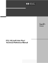
PTX Linefeed
Determines the vertical text alignment when a Linefeed command is sent.
ESC*t1L Enabled
ESC*t0L Disabled
When PTX Linefeed is enabled, the Linefeed moves to the next line as calculated from the Top of Form position, thereby retaining vertical text alignment. When printing graphics or bar codes, you may want to set the PTX
Linefeed parameter to Enable to maintain text alignment.
When PTX Linefeed is disabled, the Linefeed is to be performed as calculated from the bottom of the graphics or barcode, thereby disrupting the vertical text alignment.
See Figure 1 for an example of this parameter enabled and disabled.
LINE 1
LINE 2
LINE 3
PTX Linefeed Enabled
Linefeed
LINE 1
LINE 2
LINE 3
PTX Linefeed Disabled
Linefeed
Figure 1. PTX Linefeed
59
Chapter 2 Configuring the PCL-II Emulation with Control Codes
Programmable Reset
The programmable reset escape sequence (ESCE) causes the printer to eject paper to the top-of-form (position 0,0) if not already at top-of-form. This command resets all current printer configuration values to the following states. The printer remains on-line after a programmable reset. When the printer is reset, it is set to a known state as follows:
• Primary and secondary character sets (fonts) as configured from the control panel.
• Vertical line spacing (6/8 LPI) as configured from the control panel.
• Paper moves to the next Top of Form position (if not currently at Top of
Form).
• Data buffer is printed and then the buffer is cleared.
• Standard VFC channel assignments selected as defined by physical page length.
• Margins set at maximum limits and/or Left margin set at first column (0).
• Physical page length remains as configured from the control panel.
• Logical page length = physical page length
• Text length = logical page length minus one inch
• All character font attributes (symbol set, pitch, style, and density) default to the character font configured from the control panel.
• Display functions off and Underline enhance disabled.
• Perforation skip mode as configured from the control panel.
• Enable/Disable Label Card as configured from control panel.
• Printronix linefeed emulation as configured from control panel.
• Raster graphics horizontal resolution as configured from the control panel. Vertical resolution set to 72 dots per inch.
Programmable VFC
Programmable VFC allows the user to specify paper movement information other than the standard VFC definitions shown in Table 12. VFC information is stored in the memory (RAM) table just as the standard VFC is, only the bytes of information are loaded into RAM using the following escape sequence:
ESC&l[ byte count ]W[ VFC data ]
The byte count parameter specifies the number (in decimal 0 - 255) of VFC data bytes to expect immediately following the termination of the escape sequence.
Note An even byte count must be indicated. If an odd byte count is indicated, the VFC table in RAM will not be overwritten and the data bytes following the ESC sequence are read and discarded.
60
Programmable VFC
VFC data is the binary data which is loaded into the VFC table in RAM. These
8-bit bytes are sent in the following order following the ESC sequence terminator: the most significant byte of the first word followed by the least significant byte of the first word, followed by the most significant byte of the second word, etc. The most significant bit of each word is channel 16 and the least significant bit of each word is channel 1.
VFC Data = (MS byte) (LS byte) (MS byte) (LS byte) . . .
(word 1 = line 1) (word 2 = line 2) . . .
Once the VFC has been loaded into the RAM table, the VFC channels are selected using the ESC&l[0 through 16]V sequence in the same manner as the standard VFC. The standard and programmable VFC both use the same table in RAM. Resetting the printer causes the standard VFC to be recalculated using the current page and text (form) length and a new table to be overwritten in RAM. The VFC table is also recalculated when the line spacing, text length, or page length changes.
Note If the I/O is configured for 7 bit data, channels 8 and 16 cannot be downloaded with confidence since the eighth bit is used for the communication protocol. Selecting channels 8 or 16 for 7 bit data is not recommended.
Special VFC Considerations
Before loading a VFC table, it is recommended that a VFC select of channel 0 be performed. This will bring the printer to the top of the physical page.
When a programmed VFC is loaded into RAM, the logical page length is automatically calculated using the following formula:
Logical Page Length (in number of lines) = byte count /2
The example on page 67 shows a VFC table which uses “standard” VFC definitions and also illustrates a programmable VFC.
Example: Defining a 3.5 inch form at six lines per inch.
1 inch = 6 lines x 3.5 inches = 21 lines
61
Chapter 2 Configuring the PCL-II Emulation with Control Codes
Programmable VFC Using PCL
Programmable VFC’s using PCL seem to cause a lot of problems and misunderstandings. Most of the misunderstanding concerns the use of the escape sequence used to set the VFC file. This escape sequence is used to override the default VFC of the printer. This escape sequence can be hardcoded into a program or ASCII file.
VFC’s are best understood by reviewing an actual example of how to implement them. For this discussion, the example consists of a 3.5 inch form at six lines per inch with several different channels defined for use on the form to be printed.
1 inch = 6 lines per inch x 3.5 inches = 21 lines; therefore this would be a 21 line form.
Note The TEXT LENGTH command could be used in conjunction with the standard VFC and accomplish the above requirements. The assumption is there are reasons to use a customized VFC; this example has been simplified for clarification purposes.
First, establish the VFC length: with a 3.5” form and 6 LPI print, we have 21 potential lines of print (3.5 x 6 = 21). Refer to the following figure for an example of the desired finished output.
There are many methods to accomplish this task. The simplest way is to provide a “1” in CH3 (Channel 3) for all possible print lines and simply call
CH3 for each line (including blank lines). This is called “line counting” and leaves the burden of positioning with the programmer (adding or deleting a line causes an adjustment elsewhere to be made).
EXAMPLE FORM
Line 1
Line 2
Line 3
Line 4
Line 5
Line 6
Line 7
Line 8
Line 9
Line 10
Line 11
Line 12
Line 13
Line 14
Line 15
Line 16
Line 17
Line 18
Line 19
Line 20
Line 21
Company name
Street address
Opening line
Body
Body
Body
Closing line
P.S. line
62
Programmable VFC
A second method involves only providing a “1” in CH3 where print will occur.
The programmer then simply calls CH3 and the blank lines are skipped.
There still is no flexibility for adding or deleting lines without VFC modification, but line counting is minimized.
A third method involves assigning VFC channels to each section of the letter and performing a call to CH3 within each section. To do this, the manufacturer highly recommends following these guidelines:
• CH1 should always define TOF and must be present for a valid load.
• CH2 should always define BOF allowing for vertical margin (if any) and must be present for valid paper out conditions.
• CH3 should be present for any potential print line except in the vertical margin area (if any).
For this example, CH1 will occur at line 1 and is aligned with the Company
Name. We will arbitrarily assign CH4 to occur at line 7 (Opening Line), CH5 to occur at line 10 (Body), CH6 to occur on line 17 (Closing Line) and CH7 to occur on line 20 (P.S. Line).
With the above channel assignments in mind, the programmer would call CH1 to begin the letter. After printing the name and address (using calls to CH3 to
“move” to each line) the programmer would call CH4 to skip to line 7 and print the opening line. Next, a call is made to CH5 to skip to line 10 and print the body, CH6 to print the closing and CH7 to print the P.S. line. This gives each section flexibility by allowing variable sizes, limited by the physical room available before interfering with the next section and avoiding the drudgery of line count.
The above VFC would look like:
Channel 1 2 3 4 5 6 7 8 9 10 11 12 13 14 15 16
Line 1
Line 2
Line 3
Line 4
Line 5
Line 6
Line 7
Line 8
Line 9
Line 10
Line 11
Line 12
Line 13
Line 14
Line 15
Line 16
Line 17
Line 18
Line 19
Line 20
Line 21
1
1
1
1
1
1
1
1
1
1
1
1
1
1
1
1
1 1
1
1
1
1
1
1
1
1
1
Note A “1” corresponds to a hole punched in a physical paper tape.
63
Chapter 2 Configuring the PCL-II Emulation with Control Codes
Notice that for each line channel 3 is selected, this would select a single space advance. A 1 could be placed in any or all other channels and the VFC would still be valid since the printer will only look at the channel selected and advance to the next line that contained a 1 in that channel. For example, if the printer was on line 2 and channel 7 was selected, the printer would advance or slew down to line 20 which is the first line where there is a “1” in channel 7.
The next step would be to convert the above VFC definition into the escape sequence format. The VFC data portion of the escape sequence reverses the order of the channels. Once reversed, the 16 bits are then divided into two, 8bit bytes, with channel 16 being the Most Significant Bit (MSB) of the word and channel 1 the Least Significant Bit (LSB) of the word. Refer to Table 10.
Since the escape sequence requires the VFC data to be in ASCII format this binary data must be converted to ASCII. As in our example, many characters may convert to “unprintable” ASCII characters (below ASCII OCTAL 037).
Refer to the ASCII Symbol Set chart in Appendix A. Entering unprintable data can be done in several ways:
The easiest and preferred method involves using “dummy” VFC channels to cause the converted character to become a printable one. For example, always have bit 7 and bit 15 a “1”, thus adding %100 to the unprintable character, and eliminating the confusion of entering unprintable data. Do not
“call” the corresponding channel bit 7 or 15 or else improper spacing will occur.
If the VFC channels that bits 7 and 15 represent must be used, these unprintable characters must be manipulated for data entry. In most cases, this can be dealt with by using the DISPLAY FUNCTIONS mode of your terminal.
Type in the “ESC&l[ byte count ]W” followed by the ASCII characters using the
CONTROL key with the corresponding letter. (Since the CONTROL key subtracts %100 (100 OCTAL) simply add %100 to the “unprintable” character.
For example, 00000101 converts to %5, adding %100 gives you a %105 which is an E, therefore, pressing a CONTROL E gives the desired result.)
If your terminal doesn't have a DISPLAY FUNCTIONS mode, some EDITOR programs allow entering the OCTAL equivalents. Some editors do not allow the user to directly enter OCTAL numbers. In this case, a “dummy” character would be entered as the VFC data. Next, the EDITOR “CHANGE” command would be used to change the dummy character to the desired ASCII character. For example, place an “x” as a dummy character in the VFC data and use the CHANGE command to replace the “x” with an ASCII 01 (SOH character) by typing “CHANGEQ “x” to ‘01”. This would replace the “x” with the unprintable ASCII 01; your escape sequence would appear one character shorter without DISPLAY FUNCTIONS mode turned on.
This could also be accomplished by changing the specific column to the
ASCII character required. It is important to specify the starting and stopping column or the CHANGE command will act as a column INSERT. For example, if column 10 on line 2 is to be changed to an ASCII 04 you would type “CHANGEQ 10/10 TO '04 IN 2”.
Note The “ ' ” is the single quote and not the prime character.
64
Programmable VFC
The HP 3000 Workstation Configurator allows entering the VFC data in an initialization string. This is only applicable when using a printer with a serial interface and has some limitations. The most significant limitation is that the initialization string can contain only 120 formatted (compiled) characters. This limits use to VFCs of 57 lines or less (6 escape sequence characters + 114
VFC data characters = 120). Any other commands in the initialization string reduces this further. Space available in the initialization string data entry field
(three lines) is NOT an accurate indicator of the number of formatted characters; careful counting is necessary. Using VFC channels 8 and 16 is also not allowed due to a limitation of entering data with an octal value above
177.
There are several methods to enter data in the Workstation Configurator:
• Entering data as a decimal number, i.e. 13 for a carriage return.
• As an OCTAL number (one byte at a time) by preceding the number with the % sign.
• As a two or three character mnemonic such as BS or DC1 (see Appendix
B of the Workstation Configuration manual).
• By entering the control characters with the up-arrow or circumflex character preceding the character, i.e. a backspace would be an ^H.
• By entering the actual ASCII character within single quotes, i.e. ’A’ would equate to an OCTAL %101.
Each character entered, with the exception of multiple ASCII characters within the single quote, MUST BE separated by commas. An example would be
“ESC, '&16W', %101, 'ABC', BS, 13”.
Note Only one byte may be specified at a time in OCTAL, thus allowing a maximum of OCTAL 377 which would place a 1 in columns 1-8.
65
Chapter 2 Configuring the PCL-II Emulation with Control Codes
Line 1
Line 2
Line 3
Line 4
Line 5
Line 6
Line 7
Line 8
Table 10. Converting VFC Format to VFC Data
Most Significant Byte Least Significant Byte
16 15 14 13 12 11 10 9 8 7 6 5 4 3 2 1 Octal
MSB/LSB
0 0 0 0 0 0 0 0 0 0 0 0 0 1 0 1 %000%005
0 0 0 0 0 0 0 0 0 0 0 0 0 1 0 1 %000%004
ASCII
MSB/LSB
NulEnq
NulEot
0 0 0 0 0 0 0 0 0 0 0 0 0 1 0 1 %000%004 NulEot
0 0 0 0 0 0 0 0 0 0 0 0 0 1 0 0 %000%004 NulEot
0 0 0 0 0 0 0 0 0 0 0 0 0 1 0 0 %000%004
0 0 0 0 0 0 0 0 0 0 0 0 0 1 0 0 %000%004
NulEot
NulEot
0 0 0 0 0 0 0 0 0 0 0 0 1 1 0 0 %000%014 NulFF
0 0 0 0 0 0 0 0 0 0 0 0 0 1 0 0 %000%004 NulEot
Line 9 0 0 0 0 0 0 0 0 0 0 0 0 0 1 0 0 %000%004 NulEot
Line 10 0 0 0 0 0 0 0 0 0 0 0 1 0 1 0 0 %000%024 NulDc4
Line 11 0 0 0 0 0 0 0 0 0 0 0 0 0 1 0 0 %000%004 NulEot
Line 12 0 0 0 0 0 0 0 0 0 0 0 0 0 1 0 0 %000%004 NulEot
Line 13 0 0 0 0 0 0 0 0 0 0 0 0 0 1 0 0 %000%004 NulEot
Line 14 0 0 0 0 0 0 0 0 0 0 0 0 0 1 0 0 %000%004 NulEot
Line 15 0 0 0 0 0 0 0 0 0 0 0 0 0 1 0 0 %000%004 NulEot
Line 16 0 0 0 0 0 0 0 0 0 0 0 0 0 1 0 0 %000%004 NulEot
Line 17 0 0 0 0 0 0 0 0 0 0 1 0 0 1 0 0 %000%044 Nul$
Line 18 0 0 0 0 0 0 0 0 0 0 0 0 0 1 0 0 %000%004 NulEot
Line 19 0 0 0 0 0 0 0 0 0 0 0 0 0 1 0 0 %000%004 NulEot
Line 20 0 0 0 0 0 0 0 0 0 1 0 0 0 1 0 0 %000%104 NulD
Line 21 0 0 0 0 0 0 0 0 0 0 0 0 0 1 1 0 %000%006 NulAck
@D
@D
@$*
@D
@D
@D*
@F
@D
@D
@D
@D
@L
@D
@D
@T
@D
@D
@D
@D
CTL
MSB/LSB
@E
@D
* DO NOT depress the Control Key on these BOLDFACE characters since they are printable characters.
This VFC data can now be entered into the escape sequence in an ASCII file or programmatically and be either embedded into the application or merged with the spool file.
66
Programmable VFC
Example VFC Data Entry Methods
The example escape sequence may be created while the DISPLAY
FUNCTIONS key has been enabled as shown below.*
Top of Form
Bottom of Form
Single Spacing
Double Spacing**
Triple Spacing**
Half Form
Quarter Form
Tenth Line
Bottom of Form
Bottom of Form - 1
Top of Form - 1
Top of Form
Seventh Line
Sixth Line
Fifth Line
Fourth Line
Line 1
Line 2
Line 3
Line 4
Line 5
Line 6
Line 7
Line 8
Line 9
Line 10
Line 11
Line 12
Line 13
Line 14
Line 15
Line 16
Line 17
Line 18
Line 19
Line 20
Line 21
Channels 1 2 3 4 5 6 7 8 9 10 11 12 13 14 15 16
1 1
1
1
1 1
1
1
1
1 1
1
1 1 1
1
1 1
1
1 1
1
1
1 1 1
1
1 1 1
1 1
1
1 1
1
1
1
1
1
1 1
1
1
1
1
1
1
1
1
1
1
1
1
1
*This sample shows a 21-line VFC table at 6 LPI. The text ends at line 14, leaving 6 blank lines (one inch) at the bottom of the page.
**These channels cause a move to the next double/triple space line.
Press the CONTROL key before each letter of the VFC data except for the two BOLDFACE characters.
ESC&142W@E@D@D@D@D@D@L@D@D@T@D@D@D@D@D@
$@D@D@D@F
VFC data
This would display the corresponding ASCII character, i.e., the Nul for CTL
@.
67
Chapter 2 Configuring the PCL-II Emulation with Control Codes
Another method using a text editor would be to do a CHANGE command replacement to convert the characters to ASCII characters. This is shown as:
\ADD 1
1 ESC&142WabcdefghijklmnopqrstuvwxyzABCDEFGHIJ
2 //
\CHANGEQ 7/7 TO ’00
.
.
\CHANGEQ 8/8 TO ’05
\CHANGEQ 9/9 TO ’00
.
\CHANGEQ 48/48 TO ’06
This could also be input by not entering the letters, but simply changing the specific column to the desired ASCII character. In the above example the
“abc... HIJ” would not be entered and the CHANGE command would be used as follows:
.
.
.
\CHANGEQ 7 TO '00 \CHANGEQ 8 TO '05
An example for the Workstation Configurator might be input in several formats. An example showing the various formats is shown below:
ESC, '&142W' ,NUL,ENQ, '@, 'D, 00, 04, %0, %4, ....%0, %6
As you can see, the escape sequence for the Programmable VFC can be quite complicated. This should only be used after attempting to satisfy VFC requirements using the standard (computed) VFC and the TEXT and PAGE
LENGTH escape sequences.
The most common errors in successfully implementing the Programmable
VFC escape sequence usually involve improper VFC byte counting or attempting to manipulate “unprintable” characters and getting confused.
Converting these “unprintable” characters to printable ones is the easiest way to avoid data entry confusion.
Summary of Recommended Steps to Implement Programmable VFC
1.
Layout the required VFC in a standard channel 1-16 format.
2.
Reverse the resulting bit image so that channel 1 is now where channel
16 was and channel 16 is now where channel 1 was.
3.
Divide this 16 bit image into two 8-bit bytes.
4.
Decode these 8-bit bytes into ASCII characters using the chart in
Appendix A. If the corresponding decoded character is not a printable character (below %37), it is highly suggested to convert to one by using a
“dummy” channel (7 and/or 15).
5.
Enter these characters into the Programmable VFC escape sequence as the VFC data. This data MUST be an even byte count and is CASE
SENSITIVE (upper/lower). As in all escape sequences, do not include the brackets ([ ]); they are for clarification only.
68
Raster Graphics
6.
This escape sequence must be sent to the printer before the data by embedding in the application or as part of an initialization string. A programmable or hardware RESET will clear the VFC RAM causing the printer to return to the default VFC.
Note If either the RS-232E or the RS-422B interface is installed in the printer, the interface can be configured to have such things as STRIP NULLS AND DELETES. The Null and/or
Delete character could be used as valid characters, so the user must either combine other channels on the same line to generate another character, or not configure the printer to strip these characters. Another factor may be the use of 8-bit data. If the user desires to use channels 8 and 16, then 8-bit data must be configured. For more detail please refer to the
LineJet Printers: User’s Guide manual.
Raster Graphics
Graphics are sent to the printer using the following escape sequences:
ESC*t[70, 140]R Raster graphics resolution
ESC*r#L Horizontal raster graphics resolution
ESC*r#V Vertical raster graphics resolution
The ESC*r#L and ESC*r#V escape sequences allow you to set the horizontal and vertical raster graphics resolutions independently. Valid raster graphics resolutions are 70 DPI by 72 DPI, 140 DPI by 72 DPI, 70 DPI by 144 DPI, and
140 DPI by 144 DPI. The following table lists the graphics resolution and the corresponding escape sequence used to select that graphics resolution.
There are many different valid ways to select a given graphics resolution. The following table lists only one of the many valid ways.
The ESC*t#R escape sequence allows you to select a graphics resolution of either 70 x 72 dots per inch (default) or 140 x 144 dots per inch (high resolution). For example, to specify high-resolution, you would send the
ESC*t140R escape sequence to the printer. Using the standard resolution, the maximum amount of graphics data that can be printed is 115.5 bytes versus 231 bytes for high-resolution.
Table 11. Graphics Resolution
Horizontal DPI
70
140
70
140
72
Vertical DPI
72
144
144
Escape Sequence
ESC*r70l72V
ESC*r140l72V
ESC*r70l144V
ESC*r140l144V
ESC*rA Prepare for raster graphics (PCL Level I)
ESC*b[ # of bytes ] W[ binary data ] Raster data transfer (PCL Level I)
ESC*b[
ESC*rB
# of raster lines ]Y Move paper # number of raster lines
Raster graphics complete (PCL Level I)
69
Chapter 2 Configuring the PCL-II Emulation with Control Codes
The ESC*rA sequence informs the printer that a raster graphics dump is to follow the sequence. If the printer has received a partial line of ASCII data before this sequence is received, this escape sequence causes the ASCII data to be printed and a carriage return and line feed to be performed.
The ESC*b#W[ binary data ] sequence actually sends the raster data to the printer. This escape sequence must be sent for each raster line to be printed.
The # of bytes parameter is the decimal number of bytes of binary graphics data to be sent to the printer. The binary data consists of a 1 for every dot to be printed and a 0 for every blank space.
The ESC*b#Y escape sequence allows you to skip multiple adjacent blank lines. The # of raster lines parameter is the decimal number of blank raster lines to skip. The size of the blank raster line to be skipped is equivalent to the currently set vertical raster graphics resolution. The advantage of using this escape sequence over sending multiple raster data transfer escape sequences containing blank raster lines is the escape sequence is processed faster and the paper is moved faster.
The ESC*rB sequence informs the printer that all the raster data has been transferred.
The following example illustrates how to send three lines of raster graphics to the printer.
ESC*rAESC*b2WDc
ESC*rA Prepares printer for raster graphics
ESC*b2W Indicates two bytes of data to follow
D c
First byte of graphics data
Second byte of graphics data
ESC*b2WL@
ESC*b2W Indicates two bytes of data to follow
L First byte of graphics data
@ Second byte of graphics data
ESC*b2W$+ESC*rB
ESC*b2W Indicates two bytes of data to follow
$ First byte of graphics data
+
ESC*rB
Second byte of graphics data
Raster graphics complete
Many systems perform an automatic line feed after each line of data. The system’s automatic line feed must be suppressed or else the raster lines will not be adjacent to each other. A file equation which specifies the line length
(for example, RESC=-219) may be used to suppress the automatic line feed along with carriage control directives, such as “+”.
Graphics files must be raster graphics files in the format described here in order to print on the printer. To print vector graphics files, such as graphics files created for plotters, a vector-to-raster conversion must be performed on the data. (Vector-to-raster conversion is NOT a standard feature of the printer.) Text and graphics cannot mix on the same line due to grid conflicts.
Raster graphics use 8-bit data.
70
Self-test
Self-test
(PCL Level I)
ESCz prints the PCL-II configuration report, which shows available character sets, symbol sets, bar codes, etc.
Standard (Computed) VFC
The printer VFC uses the logical page and form length (text length) to calculate the distance to be skipped for each VFC channel. This information is then loaded into the printer's VFC “table.” The “table” is 16 channels wide and n lines long, where n is the logical page length in number of lines. A VFC channel contains a 1 in this table on every line it can access. If the VFC channel cannot access the line, a 0 is placed on that line for that channel. For example, to specify a skip to the next half form, a program would specify VFC channel 6. Notice in the sample on page 67 that 1's are placed in the table at the half form position (lines 1 and 9). Then, for example, if the printer has finished printing line 2 and channel 6 is selected, the paper will be advanced to line 9.
To use the standard VFC, perform the ESC&l[0-16]V sequence using the appropriate parameter number listed in Table 12.
Stroke Weight (Bold)
The Stroke Weight command designates the thickness of the strokes that compose the characters of a font.
ESC(s#B Primary stroke weight
ESC)s#B Secondary stroke weight
The value field (#) must be 0 for standard stroke weight, or 3 for bold stroke weight.
Switching Character Fonts
Character fonts can be accessed using the Shift In/Shift Out (SI/SO) control codes.
The SO (CTRL N) control code is sent to the printer to access the secondary font; the SI (CTRL O) control code is sent to select the primary font.
71
Chapter 2 Configuring the PCL-II Emulation with Control Codes
Text Length (Vertical Margin) Selection
(PCL Level II)
The length of a form within a logical page is set using the ESC&l[1-128]F sequence, where the number of lines desired (1-128) is specified. The first line of text is printed at the Top of Form position. The physical page length minus the text length defines the total vertical margin (top plus bottom margin) for the page.
If a text length of zero is received, the text length defaults to one inch less than the logical page length. The default text length, which is invoked any time the logical page length is changed, is one inch less than the logical page length. If the logical page length is one inch or less, the text length is set equal to the logical page length.
Transparent Print Data
This feature allows the printing of binary data which is required in certain applications. The escape sequence ESC&p[ # of bytes ]X enables the printer to print data as in the display functions mode, except that no control codes or escape sequences (including CR and ESCZ) are executed. The number specified in the value field is the exact number of bytes that will be interpreted as binary.
Underline Mode
The ESC&dD sequence enables the automatic underlining mode. In this mode, each printed character and space is underlined until the printer receives an ESC&d@ sequence. The underline enhancement is disabled in the default state. Underlining only affects forward horizontal movement such as SP (space), DATA, or forward horizontal cursor moves; reverse movements such as BS (backspace), CR (carriage return) and negative horizontal cursor moves are not affected.
72
Vertical Forms Control (VFC)
Vertical Forms Control (VFC)
Vertical forms control (VFC) is a feature which allows increased throughput by enabling the printer to skip to predetermined print locations. Key page locations, such as top of form, half form, double space, and triple space, are referred to as channels (0 through 16) and are stored in a VFC “table.”
The printer has both a standard (computed) VFC and a programmable VFC.
Note In most situations, the printer's standard (computed) VFC page length setting, as determined from the front panel, meets the application requirements. Refer to the LineJet
Printers: User’s Guide for information on setting the page length from the front panel.
Prefix
ESC&l
Table 12. VFC Default Channel Definitions
12
13
14
15
16
8
9
10
11
6
7
4
5
2
3
0
1
Parameter Terminator v/V
Explanation
*Conditional Top of Physical Page
Top of Form (first line of text)
Bottom of Form (last line of text)
Single spacing
**Double spacing
**Triple spacing
Half form
Quarter form
Tenth line
Bottom of Form
Bottom of Form - 1
Top of Form - 1
Top of Form
Seventh line
Sixth line
Fifth line
Fourth line
*All escape sequences except ESC&l0V refer to the logical page rather than the physical page. This escape sequence causes a skip to the top of the next physical page (unless already at top of page).
**These channels cause a move to the next double/triple space line, and therefore may not actually perform a double/triple space.
73
Chapter 2 HP 3000 Information
HP 3000 Information
This section contains information which is specific to HP 3000 users. It explains the use of the feature access and transparent modes, environment files, downloading VFC files, carriage control, perforation skip mode, and discusses recoverability.
Feature Access and Transparent Modes
During system device configuration, the LineJet printer is configured to default to either the transparent or feature access mode. In the transparent mode, the printer prints (but does not execute) all data including control codes and escape sequences. In the feature access mode, the supported control codes and escape sequences are executed. The user can access the non-default mode using either the FDEVICECONTROL intrinsic (for programs) or an environment file.
VFC Download with a Serial Interface
Typically, VFC download was only possible for 256X and HP 2300 Series printers with an HPIB interface using the CIPER driver. MPE V/E T-MIT and above support a software product called Workstation Configurator that allows serial printers to “download” VFC by placing the VFC escape sequence in an initialization string instead of embedding them within the application.
The process of downloading VFC using Workstation Configurator is different than when using an HPIB printer. Workstation Configurator has a utility that allows modification to two different files that allow for, among other things, setting initialization strings, flow control, and VFC. Workstation Configurator has a terminal type file that is used for certain functions and a VFC file that is used for setting the initialization strings and the VFC. These files are not in the same format as the HPIB VFC file and must be created using Workstation
Configurator.
When using the VFC file created using Workstation Configurator, the user must specify the terminal type file in the HP 3000 I/O Configuration, or by referencing it with the ENV parameter of the FILE statement. The
DOWNLOAD command will NOT operate in this configuration.
If the ENV parameter of the FILE statement is used, the associated terminal type file that has been configured with the printer will still be sent to the printer first and the terminal type file that has been specified with the ENV parameter will be sent NEXT. This does not create any problems, it just should be noted when using a datascope or analyzing a spool file.
74
Carriage-Control Directives
Carriage-Control Directives
The HP 3000 software drivers allow users to embed the following carriagecontrol directives in files:
ASCII SYMBOL
“ ”
“+”
“-”
“0”
“1”
“C”
CARRIAGE ACTION
Single space (with or without automatic page eject).
No space, return (next printing at column 1).
Triple space (without automatic page eject).
Double space (without automatic page eject).
Page eject (form feed). Selects VFC channel 1.
Sets single-space option, without automatic page eject (66 lines-per-page).
The carriage-control directive is placed in column 1 of the file and is executed
(but not printed) when the file is printed. When using this feature, all other characters placed in column 1 will be ignored (not printed).
When using the carriage-control directives, the application must use carriage control and [;CCTL] must be included in the file equation as shown in the following example:
:file [filename];dev=[device number];cctl
Graphics
When using graphics, the line feed generated by the driver must be suppressed or there will be 1/6” or 1/8” spacing between raster lines. One way to do this is to add a “+” to the front of the file as carriage control (the file equation must have “;CCTL.”)
Printing in the Perforation Skip Region
When using the HP 3000, an automatic page eject occurs when the perforation skip region is entered. There are three ways to avoid a page eject and allow printing in the perforation skip region:
• Set the text length = logical page length = physical page length on the front panel.
• Use carriage control with a “C” in column 1 (the application must use carriage control).
• Set the carriage control to null (no CR-LF at end of line) and programmatically add a CR-LF to the end of each record.
75
Chapter 2 HP 1000 Information
HP 1000 Information
The LineJet printer may be commanded into either the transparent or feature access mode. In the transparent mode, the printer prints (but does not execute) all data including control codes and escape sequences. In the feature access mode, the control codes and escape sequences are executed.
All configuration information is located in the DVC12 Graphics Printer Driver
Reference Manual (P/N 92068-90022). For HP 1000 A-Series information, refer to the Driver Reference Manual (P/N 92077-90011) and the RTE-A
System Design Manual (P/N 92077-90013). To set transparent mode with the
DVC12 driver, the following command can be used where LU is the logical unit address of the printer: --CN,LU,30B,20B
Downloading VFC
All information concerning downloading VFC files is contained in the DVC12
Graphics Printer Driver Reference Manual (P/N 92068-90022).
B-4 Carriage-Control Directives
The HP 1000 software drivers allow users to embed the following carriagecontrol directives in files:
ASCII SYMBOL
“ ”
“+” or “*”
“-”
“0”
“1”
CARRIAGE ACTION
Single space (with or without automatic page eject).
No space, return (next printing at column 1).
Triple space (without automatic page eject).
Double space (without automatic page eject).
Page eject (form feed). Selects VFC channel 1.
The carriage-control directive is placed in column 1 of the file and is executed
(but not printed) when the file is printed. When using this feature, all other characters placed in column 1 are ignored (not printed).
Perforation Skip Mode
To override the HP 1000 driver's automatic page eject, see the Control
Requests section of the DVC12 Graphics Printer Driver Reference Manual
(P/N 92068-90022).
76
advertisement
* Your assessment is very important for improving the workof artificial intelligence, which forms the content of this project