advertisement

CHARGING THE ACCUMULATOR
To check or charge the accumulator the following equipment is required:
• Charge kit (Part Number 31254) Includes the following:
NOTE:
It may be necessary to set the regulator at 650–
700 psi/41–48 bar to overcome any pressure drop through the charging system.
– Accumulator tester (P/N 02835).
– Charge assembly (P/N 15304). Includes a liquid-filled gauge with snub valve, hose and fittings.
6. Open the valve on the charging assembly hose.
When the tester gauge reads 600–700 psi/41–48 bar, close the valve on the charging assembly hose and remove the charging assembly.
• NITROGEN bottle with a 800 psi/56 bar minimum charge (not a part of 31254 kit).
1. Holding the chuck end of the Stanley tester
(P/N 02835), turn the gauge fully counterclockwise
7. Turn the gauge end of the tester fully counterclockwise to retract the plunger in the chuck. Remove the tester from the charge valve.
8. Replace the valve cap.
Charging the Accumulator (BR72125S & BR72135S)
2. Thread the tester onto the charging valve of the tool accumulator (do not advance the gauge-end into the chuck end. Turn as a unit). Seat the chuck on the accumulator charging valve by hand tightening only.
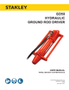
CW
TESTER CHARGING
VALVE
1. Follow Steps 1 through 3 under CHARGING THE
ACCUMULATOR.
2. Read the pressure on the gauge. It should be between 500–700 psi/35–48 bar.
3. Advance the valve stem by turning the gauge-end clockwise.
CHUCK
3. If the pressure is low, recharge the tool.
4. Connect the charging assembly to the valve on the tester.
5. Adjust the regulator on the nitrogen bottle to 600 psi/42 bar.
ACCUMULATOR TESTER ( P/ N 02835 ) LOCATION OF CHARGING VALVE
Figure 2
(
Nitrogen Tank
)
31254 ACCUMULATOR CHARGE KIT
Includes: Liquid Filled Gauge w/Snub Valve,
Hose, Charge Fitting, 02835 Tester, and Box
(not pictured)
12 ► GD50 User Manual
CW
TESTER CHARGING
VALVE
CHUCK
GAUGE
ACCUMULATOR TESTER ( P/ N 02835 )
Figure 2
LOCATION OF CHARGING VALVE
advertisement
* Your assessment is very important for improving the workof artificial intelligence, which forms the content of this project