advertisement
 Mounting and Wiring Guide | Manualzz")
JACE-8000 (12977) Controller
Mounting and Wiring Guide
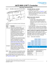
Figure 1 JACE-8000 controller (with one option module).
Included with the controller
•
JACE-8000 (12977) controller.
•
MicroSD card in plastic case. See
•
Dual band 2.4/5.8GHz antenna for WiFi, two 3-position
RS485 connector plugs, one 2-position power connector plug, and a grounding wire.
•
A JACE-8000 Controller (12977) Quick Start Guide
This document covers mounting and wiring of the following products.
Model
12977
(JACE-8000)
Description
DIN rail-mount, 24Vac/dc powered,
Niagara 4® area controller, using an ARM®
Cortex™-A8 1Ghz processor, 1GB DDR3
SDRAM, 2Mb (megabit) Serial FRAM, and up to 4GB microSD Flash memory. Two
10/100Mbit Ethernet ports, two electrically isolated RS485 ports and an integral
802.11a/b/g/n WiFi adapter are standard. The integral power supply requires either 24Vac,
24Vdc, or a wall-mount AC power adapter.
Internal battery backup is not required or available.
DIN rail-mount option modules directly attach for additional communications ports, including types for LonWorks® (FTT-10), RS232
(DB-9), and dual RS485. The controller supports up to four (4) option modules. See
“Option module and capacity considerations” .
Remote I/O expansion modules (T-IO-16-485) are supported by RS485 connection to the
controller. See “RS485 wiring,” page 5.
WPM-8000 Wall-mount, Class 2 universal AC power adapter supplying 24Vdc to a cable with a barrel-connector plug. Different models are available, where -XXX is either: -US, -EUR, or
-UK (vary by AC wall plug).
NOTE:
Niagara 4 is required for any JACE-8000 controller.
A future update release of NiagaraAX-3.8 should also provide support of many controller features.
See JACE-8000 Niagara 4 Install and Startup Guide for
Niagara 4 software installation and configuration details. Also
see “Related documentation,” page 8.
Material and tools required
•
One of the following:
– UL listed, Class 2, 24Vac transformer, rated at minimum of 24VA. A dedicated transformer is required (cannot power additional equipment), or
– 24Vdc power supply, capable of supplying at least
1A (24W), or
– WPM-8000 wall-mount AC power adapter with barrel connector plug.
•
DIN rail, type NS35/7.5 (35mm x 7.5mm) and DIN rail end-clips (stop clips), recommended for any installation with option modules. Controller is also panel-mountable.
•
Suitable tools, fasteners, and accessories for mounting.
Option module and capacity considerations
The controller supports a maximum total of four option
(expansion) modules in certain combinations. If you use two
RS485 option modules, you are limited to one additional
“non-RS485” module (LON or 232) for a total of three. The following figure shows some example combinations.
Figure 2 Valid module combinations
485
485
485
485
232 or
LON
485
485
485
485
232 or
LON
232 or
LON
232 or
LON
485
485
B a s e b o a r d :
485
485
232 or
LON
232 or
LON
232 or
LON
232 or
LON
EXPANSION 4
EXPANSION 3
EXPANSION 2
EXPANSION 1
Table 1 Maximum option modules supported by protocol
Expansion Module
NPB-8000-LON
NPB-8000-232
NPB-8000-2X-485
Max Components
4
4
2
JACE, JACE-8000, Niagara Framework, Niagara 4 Framework, and the Niagara AX Framework are trademarks of Tridium, Inc.
JACE-8000 Controller (12977) Mounting and Wiring Guide
December 15, 2015
1
Preparation
Static discharge precautions
Separate maximum limits may be defined in the controller’s license, such as total number of networks, devices, and integration points (capacity licensing).
Table 2 Maximum wired field bus integrations.
Protocol Max Description, Option Module
RS485
Lonworks
FTT-10
RS232
7 Two via onboard RS485, four via two Dual
RS485 option modules (2 ports each), plus one via LON or RS232.
4 Four LON option modules (1 port each module)
4 Four RS232 option modules (1 port each module)
Note that maximums in
Table 2 on page 2 do not reflect
combinations of wired field bus integrations. Two examples:
•
Two RS485 (via onboard RS485), two Lonworks FTT-10
(2 LON modules), two RS232 (2 RS232 modules).
Maximum number of option modules (4) are installed.
•
Four RS485 (2 via onboard RS485, 2 from a single Dual
RS485 module), two Lonworks FTT-10 (2 LON modules).
In this case, three (3) option modules are installed.
Future option module types may have additional maximum limits, within the “4 total” option per controller limit.
Safety precautions
Warning • Disconnect power before installation or servicing to prevent electrical shock or equipment damage.
• Use copper conductors only. Make all connections in accordance with local, national, and regional electrical codes.
• To reduce the risk of fire or electrical shock, install in a controlled environment relatively free of contaminants.
• This device is only intended for use as a monitoring and control device. To prevent data loss or equipment damage, do not use it for any other purpose.
• To comply with FCC and Industry Canada RF exposure limits for general population / uncontrolled exposure, the antenna(s) used for this transmitter must be installed to provide a separation distance of at least 20 cm from all persons and must not be co-located or operating in conjunction with any other antenna or transmitter.
General precautions
Caution Remove all power to controller before attaching
(plug in) or detaching (unplug) any option
module, to prevent possible equipment damage.
Caution Removal of the controller’s cover is not required.
No configurable or user-serviceable items (such as jumpers or a battery) require cover removal—all items are accessible as switches and connectors on the unit’s top, bottom, and side, or behind the unit’s front access door or microSD card shutter.
Static discharge precautions
The microprocessors and associated circuitry within the controller are sensitive to static discharge.
Caution • Work in a static-free area.
• Discharge any static electricity you may have accumulated. Discharge static electricity by touching a known, securely grounded object.
Preparation
Before mounting a new controller, you must insert the included microSD flash memory card. Note the card has the unique Niagara identity (host ID) for the unit, set at the factory.
Caution
Disconnect all power to the controller and use static discharge precautions
before removing or
inserting the microSD card. Otherwise, equipment damage is likely to occur.
After commissioning the controller, the card also holds the QNX operating system, Java software, installed Niagara 4 software, licenses, certificates, and file space of any installed station.
Figure 3 MicroSD card location in controller.
2
1
3
1 Access shutter for microSD card (slide to open or close).
2 Card carrier inside controller.
3 MicroSD card to insert or remove from card carrier.
Typically, the microSD card never needs removal. However in the case where a controller has been electrically damaged or found faulty, you can remove the card and install it in another like unit, so it can become a functional replacement.
2
JACE-8000 Controller (12977) Mounting and Wiring Guide
December 15, 2015
Mounting
Environmental requirements
Inserting or removing the MicroSD card
Prerequiste:
All power to the controller must be removed
(see previous
). If the unit is currently running, see
“Initiating a controller shutdown,” page 8.
Note the controller must also be unmounted from any DIN rail or screw tab mounting, as accessing the card uses space
behind the mounting base. See Figure 3 on page 2.
1.
Carefully slide the plastic microSD card shutter open.
The shutter should remain captive in the base, revealing the microSD card socket.
2.
To insert the microSD card, slide it into card carrier, label side up, until the spring catch engages.
If properly inserted, the card is behind the shutter track.
3.
To remove the microSD card, push it in, until the spring release pushes it partially out of the card carrier. Grasp the card, pull it completely out of the unit and store it in a static free protective case.
4.
Carefully slide the card shutter back over the card carrier opening, until it clicks in place. When properly closed, the shutter should not protrude behind the mounting base.
NOTE:
Data on the microSD card is encrypted. If you swap in a card from a previously configured unit, you must change the JACE-8000 system passphrase on the platform to match the passphrase on the new microSD card. See JACE-8000 Niagara 4 Install and
Startup Guide for details.
Mounting
Mount the controller in a location that allows clearance for wiring, servicing, and module removal.
Figure 4 Mounting dimensions of controller and option modules.
7.05" (179)
6.38" (162)
2.26"
(57.5)
2.17" (55)
2.13" (54)
4.33" (110)
9.53" (242)
12.00" (305)
14.49" (368)
16.97" (431)
Environmental requirements
NOTE:
This product is for indoor use only, altitude to
2,000m (6,562 ft.).
Ambient conditions must be within the range of:
•
Operating Temperature: -20°C to 60°C (-4°F to 140°F).
Storage Temperature: -40°C to 85°C (-40°F to 185°F).
•
Relative humidity: 5% to 95% non-condensing.
Pollution Degree 3
•
Supply (mains) voltage requirements are as follows:
– Allowable voltage fluctuation +/- 10%,
•
For a unit mounted inside an enclosure, ensure that the enclosure is designed to keep the unit within its required operating temperature range (considering a 24-watt dissipation by the controller). This is important if the controller is mounted inside an enclosure with other heat-producing equipment.
•
Do not mount the unit:
– in an area with excessive moisture, corrosive fumes, or explosive vapors.
– where vibration or shock is likely to occur.
– in a location subject to electrical noise, such as in the proximity of large electrical contactors, electrical machinery, welding equipment, and so on.
JACE-8000 Controller (12977) Mounting and Wiring Guide
December 15, 2015
3
Wiring
Wiring earth ground and power
Physical mounting
The following applies about physically mounting the unit.
•
Horizontal mounting (as shown) is
strongly
recommended, to achieve maximum heat dissipation and meet the operating temperature upper limit. Any other mounting orientation reduces this upper limit.
•
Mounting on a 35mm wide DIN rail is recommended. The controller’s unit base has a molded DIN rail slot and locking clip, as do option modules. DIN rail mounting ensures alignment of the connectors between all devices.
•
•
Dimensions of a unit with option modules are shown in
. Also see “Tab mounting dimensions,” page 10.
Mounting on DIN rail
Prerequiste:
The 35mm DIN rail should be securely mounted, with at least two screws near the rail ends. The microSD card
must be installed in the controller. See “Preparation,” page 2.
1.
Pull the controller’s locking clip down.
NOTE:
To remove a unit from the DIN rail, pull down its locking clip. Then swing the bottom out and lift the unit away from the DIN rail.
Wiring
Earth ground and power
Earth grounding provides protection from electrostatic discharge or other forms of EMI.
Figure 5 Earth ground and power options.
2.
Tilt the controller to hook over the DIN rail.
3.
Push down and in on the unit, fastening to the rail.
4.
Push the locking clip up to secure.
5.
Mount any option module onto the DIN rail in the same way.
Slide the module firmly into the controller’s connector to seat. Repeat for other modules as needed (4 maximum).
6.
Carefully secure both ends of the final assembly with DIN rail end-clips provided by the DIN rail vendor.
NOTES: Depending on power source used (see Figure 5 ):
•
2.1 (AC): Dedicated 24V transformer required, with neither side of the transformer secondary tied to ground.
•
2.2 (DC): Polarity is unimportant (uses onboard diode bridge), with neither leg tied to ground.
•
2.3 (Wall-mount AC adapter, WPM-8000) instead of wiring 24V to 2-position connector.
Wiring earth ground and power
Warning Before making power terminations, de-energize the 24V power source. Do not restore power until completing all other mounting and wiring. See
“Power up and initial checkout” on page 6.
Prerequiste:
A nearby earth grounding point.
1.
Install the included earth ground wire to the controller’s earth ground spade lug, and terminate the other end to a nearby earth ground.
2.
Unplug the controller’s 2-position power connector plug and terminate the 24V supply source (AC or DC) to the connector. Leave connector unplugged for now.
4
JACE-8000 Controller (12977) Mounting and Wiring Guide
December 15, 2015
Wiring
Communications wiring
Ports for field communications are shown in Figure 6 .
Figure 6 Communications ports on controller.
Figure 7 RS485 wiring example.
RS485 wiring
1 RS485 ports and bias switches. See
and
2 WiFi settings switch and antenna. See
3
Ethernet ports, 10/100-Mbit, RJ-45. See the “Ethernet wiring” section on page 6.
4
Earth ground and 24V power input. See “Wiring earth ground and power” on page 4.
WiFi
An integral WiFi adapter provides wireless connectivity using the IEEE 802.11a/b/g/n standard, and provides an RP-SMA antenna connector.
The WiFi configuration switch sets operation as follows:
•
OFF - (Default, middle) WiFi adapter is disabled.
•
ACC - Controller provides operation as a WiFi access point for up to 20 clients.
•
CLT - Controller operates as a client to an existing
802.11a/b/g/n router or access point.
To use, either attach the included tilt-and-swivel 2.4GHz
antenna directly (as shown in Figure 6 ), or else use an
optional coax cable extension kit (CBL-WIFI-EXT) to locate the antenna up to 2m (6.6ft) away. An associated LED remains lit whenever WiFi is enabled. See
Refer to the JACE-8000 WiFi Guide for details on WiFi configuration and factory-default settings.
RS485 wiring
On the controller’s top side, two RS485 ports operate as
COM1 and COM2. Each port is capable of up to 115,200 baud, and uses a 3-position, screw terminal connector.
1 RS485 port A (COM1) is often used to support a trunk of
T-IO-16-485 modules. NOTE: Do not mix T-IO-16-485s with other types of RS485 devices on the same RS485 trunk.
2 RS485 port B (COM2) supporting a network of other field devices using RS485 communications.
3 (NOTE): RS485 devices on the same network should use the same protocol and baud rate. Up to 32 or more devices may be supported, depending on device specifications.
Use shielded, twisted-pair, 18-22 AWG cabling to wire in a continuous multidrop fashion to other RS485 devices: “minus to minus”, “plus to plus,” and “shield to shield.”
Connect the shield wire to earth ground at one end only, for example at the controller.
shows example wiring.
RS485 bias switches —
Each RS485 port has an adjacent 3-position biasing switch, with these settings:
•
BIA - (Default, middle) RS485 biasing and termination:
2.7K Ohm bias resistors with no termination resistor
•
END - RS485 biasing and a termination: 562 Ohm bias resistors and 150 Ohm termination resistor
•
MID - RS485 biasing or termination: 47.5K bias resistors with no termination resistor
Often, adding RS-485 biasing can improve communications by eliminating indeterminate idle states.
•
BIA - (Default, middle) Often best if the RS485 trunk needs biasing, but when the controller is not installed at the end of the trunk.
•
END - Often best if the controller is installed at the end of an RS485 trunk of devices that is not already biased.
•
MID - Often best if the controller is put in the middle of an already-biased RS485 trunk.
JACE-8000 Controller (12977) Mounting and Wiring Guide
December 15, 2015
5
Power up and initial checkout
RS485 LEDs
If desired, you can change the position of an RS485 port’s bias switch while the controller is running.
Each RS485 port has two LEDs. See
Ethernet wiring
Two RJ-45 10/100-Mbit Ethernet connectors are labeled PRI
(LAN1) for primary, and SEC (LAN2) for secondary. Use a standard Ethernet patch cable to an Ethernet switch.
Caution The JACE-8000 is not compatible with a
Power-Over-Ethernet (POE) network. Connecting the JACE on a network segment which carries power may cause the unit to fail. In that event, you must disconnect it from the POE network segment and power-cycle the unit.
The factory-default IP address for PRI is 192.168.1.140. The subnet mask is 255.255.255.0. By default, the SEC (LAN2) port is disabled.
Refer to the JACE-8000 Niagara 4 Install and Startup Guide for details on the software configuration of the Ethernet ports.
NOTE:
Often, you only use PRI (LAN1 primary), unless you have a specific application for the other port. For example, isolating a driver’s network traffic, using
SEC (LAN2). Do not use SEC as the primary port.
If enabling SEC, note that PRI and SEC must be connected to different IP subnets. Further, a JACE controller does not provide IP routing or bridging operation between the two Ethernet ports.
Power up and initial checkout
Prerequiste:
Ensure power and ground wiring to the controller is ready—see wiring
“Earth ground and power” on page 4. See
Figure 8 on page 6 for the location of status LEDs.
1.
Apply power. To do this, do one of the following:
– Insert the 2-position 24V power connector plug, or
– Insert the barrel plug of the wall-mount AC adapter
(WPM-8000).
2.
Check the STAT (Status) and BEAT (Heartbeat) LEDs.
When power is applied, after 3-10 sec, the green “STAT”
LED illuminates, indicating that the system is OK, with power applied. During bootup, the “BEAT” LED may blink at 1 Hz with a 90%/10% on/off duty cycle, or in some other irregular pattern. When bootup completes, the normal 1 Hz “BEAT” LED flash at 50%/50% on/off duty cycle returns.
If after applying power, the “STAT” LED goes out, or if the
“BEAT” LED comes on (steady) and stays lit over 2 minutes, contact Systems Engineering for technical assistance. See the section
especially
For more details in this mounting and wiring document, see:
•
•
“USB ports and pushbutton switches,” page 8
For further JACE-8000 controller details, see:
•
JACE-8000 Niagara 4 Install and Startup Guide.
Explains how to commission a new JACE-8000 controller, i.e. how to install Niagara 4 software, configure Niagara platform settings, and install a Niagara station.
•
JACE-8000 USB Backup and Restore Guide
Explains USB backups and restores for a JACE-8000 controller.
•
Niagara 4 JACE WiFi Operation Guide
Explains JACE-8000 WiFi configuration and operation.
Status LEDs
The controller provides a number of status LEDs, with all but
one visible with the front access door closed. See Figure 8 .
Figure 8 LEDs and brief descriptions.
1
2 3
4 5 6
7
8
1 WiFi (Green) - Lit whenever WiFi config switch is not Off.
2 RS485 “A” (COM1): Transmit (TX, Yellow) and Receive (RX,
Green). See
3 RS485 “B” (COM2): Transmit (TX) and Receive (RX).
4 STAT (Green) - Remains lit. See
5 BEAT (Yellow) - “Heartbeat” LED that blinks at 1Hz during normal operation. See
“BEAT (Heartbeat) LED” on page 7.
6 Secondary Ethernet, SEC (LAN2) “Link” (Green) and
“Activity” (Yellow).
7 Primary Ethernet SEC (LAN1) “Link” (Green), “Activity”
(Yellow). See
“PRI, SEC (Ethernet) LEDs” on page 7.
8 (Behind Door) BACKUP - Green, typically Off unless a USB drive is inserted, or a backup, restore, or factory recovery image install is in progress. See
RS485 LEDs
RS485 port A (COM1) and RS485 port B (COM2) each have two LEDs reflecting port activity as follows:
•
Yellow (TX): indicates the controller is transmitting data on the RS485 port.
•
Green (RX): indicates the controller is receiving data from an RS485 device connected to this port.
These LEDs use a fixed “on time” when a message is detected on the port. If a receive LED is on constantly, this can indicate a wiring problem, such as a shorted wire or reversed wiring.
6
JACE-8000 Controller (12977) Mounting and Wiring Guide
December 15, 2015
Status LEDs
BACKUP LED
STAT (Status) LED
The green “STAT” LED provides a CPU machine status check, and should remain lit whenever the controller is powered. If the status LED does not light while power is applied, contact System Engineering for technical support.
BEAT (Heartbeat) LED
In normal operation, the yellow heartbeat “BEAT” LED blinks at 1 Hz, at 50%/50% on/off duty cycle.
During controller bootup, this LED may blink at 1 Hz with a
90%/10% on/off duty cycle, or in some other irregular pattern.
When bootup completes, the platform daemon is started, and the normal 1 Hz flash at 50%/50% on/off duty cycle returns.
Caution The 1Hz, 90%/10% on/off “BEAT” flash at bootup also occurs during other critical operations, such as a firmware upgrade to the controller and/or any attached modules. To be safe, do not remove power from the controller while its “BEAT” LED flashes with a 90%/10% on/off duty cycle. Wait for the normal
(50%/50%) flash to return before removing power.
If the “BEAT” LED stays on constantly, does not light, or blinks very fast, contact System Engineering for technical support.
PRI, SEC (Ethernet) LEDs
Two LEDs for each of the two LAN ports indicate as follows.
•
Green (left-side) “Link” LED operates as follows:
– Off: No Ethernet link is made.
– On: Ethernet link is made.
•
Yellow (right-side) “Activity” LED operates as follows:
– Off: No Ethernet activity.
– On: Blinking indicates activity (typical if Link is On).
BACKUP LED
A green “BACKUP” LED is behind the front access door, and
is visible only if the door is open—see Figure 9 on page 8.
Typically, this LED remains Off.
Possible “BACKUP” LED states are:
On solid: USB backup media detected. Occurs when you insert a USB flash drive, to signal a backup is possible.
Alert mode: 100ms On/100ms Off repeating (fast blink).
Occurs for several seconds in the following scenarios:
•
When USB media was detected, after the controller’s
BACKUP button is pressed (backup mode).
•
When the controller is power cycled while holding in the
BACKUP button (recovery/restore mode)
Working mode: 1s On/1s Off repeating (slow blink). Never
remove power in this mode; see the Warning on page 7.
Error mode: Two quick 200ms flashes On, 3 seconds Off, repeating.
Some scenarios where the BACKUP LED is used include:
USB drive inserted —
A USB flash drive is inserted in the USB 2.0 port, to either backup a commissioned unit to the
USB drive, or to restore an existing backup from the drive.
The BACKUP LED lights when the USB drive is mounted.
Backup —
A backup is initiated by pressing the BACKUP button from 1 to 5 seconds before releasing, where the LED starts blinking in “alert mode” for 5 seconds. Another button press in this period starts the backup, where the LED blinks in the “working mode” pattern. When the backup completes, the
LED turns Off, and the USB drive can be removed.
Boot to recover or restore image —
The unit is powered up while holding in the BACKUP button, for either:
•
(No USB media detected) A “factory defaults” recovery from an onboard partition with default image.
•
(If USB media is detected) For the restore of a backup image on the USB flash drive. Note this also requires a serial shell connection to the controller’s Debug port.
In either case, the BACKUP LED starts blinking in “alert mode” pattern. If you release the BACKUP button during this period
(within 5 seconds), initiation begins for either:
•
If no USB media is detected, the “factory defaults” recovery image installation.
•
If USB media is detected, the system enters “restore mode”. In this mode, after login with serial shell, a menu lists the available backup images on the USB flash drive.
You can select one (and enter the unique security key to initiate its installation), or alternatively select to install the
“factory defaults” recovery image.
During a recovery or restore image installation, the LED blinks in the “working mode” pattern. When the image installation completes, the BACKUP LED turns Off. A controller reboot is then required.
See the JACE-8000 Backup and Restore Guide document for complete details on JACE-8000 controller backups, restores, and recoveries.
Warning Do not remove power while a recovery image install or backup restore is in progress, meaning the BACKUP LED is flashing in “working mode” pattern (1s On/1s Off, or slow blink). Otherwise, the controller will be inoperable (“bricked”), and must be returned to a service center for repair.
JACE-8000 Controller (12977) Mounting and Wiring Guide
December 15, 2015
7
USB ports and pushbutton switches
Initiating a controller shutdown
USB ports and pushbutton switches
Behind the controller’s front access door are two USB ports, two pushbutton switches, and an associated LED.
Figure 9 USB ports and switches behind access door.
SHT/DWN
4
1
PROG
2
DEBG
3
BACKUP
BACKUP
5
1 PROG - USB 2.0 for usage with USB flash (thumb) drive.
2 DEBUG - Micro-A USB for serial debug communications.
3 BACKUP - Pushbutton switch to start a USB backup, or if held in during power up/boot up, a factory recovery image.
4 SHT/DWN - Recessed switch for controlled shutdown.
5 BACKUP - LED to indicate USB media present, or a backup, restore, or factory recovery image in progress.
•
The DEBUG port is a standard Micro-A type USB port for serial debug communications to the controller. You can use a serial terminal program (for example: PuTTY) to access the controller’s “system shell” menu. This provides access to a few basic platform settings.
Default DEBUG port settings are: 115200, 8, N, 1
(baud rate, data bits, parity, stop bits). For more details see the JACE Niagara 4 Install and Startup Guide.
Note Login requires admin-level platform credentials.
•
The SHT/DWN pushbutton initiates a “controlled shutdown” of the controller, ensuring that all station data is preserved. This provides an alternative to the platform
“stop station” command, while connected online with controller. See
“Initiating a controller shutdown” .
Initiating a controller shutdown
When locally servicing an installed and configured
(commissioned) unit, use this feature before removing power.
NOTE:
Do not initiate a shutdown or remove power if:
• BACKUP LED is blinking in “working mode”, or
• Beat LED is flashing at a 90%/10% on/off rate.
Instead, wait for the BACKUP LED to be in another state (typically Off), and the BEAT LED to flashing at the normal 50%/50% on/off duty cycle rate before
initiating a shutdown. For related details, see “BEAT
(Heartbeat) LED” and “BACKUP LED,” page 7
.
Prerequiste:
Controller has been commissioned (Niagara 4 installed, platform configured, a station installed) and the unit is running the station.
1.
Press and hold the recessed SHT/DOWN button just until the “BACKUP” LED begins flashing in “alert mode” pattern: 100ms On/100ms Off repeating (fast blink).
2.
Release the SHT/DOWN button during this alert mode.
This starts the shutdown process, where the station and software is put into a safe state. During this shutdown, the
“BACKUP” LED blinks in “working mode”.
3.
When shutdown is done, the “BACKUP” LED turns Off.
You can safely remove 24V power from the unit.
NOTE: In the case where the system cannot be put into a safe state, the “BACKUP” LED blinks in “error mode”: two quick 200ms flashes On, 3 seconds Off, repeating.
Related documentation
See the following documents for additional JACE-8000 controller information:
JACE-8000 Install and Startup Guide
Dual RS485 Option Module (12979) Install Sheet
LON Option Module (12978) Install Sheet
RS232 Option Module (12980) Install Sheet
JACE-8000 Backup and Restore Guide
JACE-8000 WiFi Guide
Data Recovery Service Guide
Niagara 4 Platform Guide
Certifications
The JACE-8000 (12977) controller has the following agency listings, compliances, and certifications:
•
UL-916, Energy Management Equipment - Edition 4
•
FCC Part 15, Class B - Federal Communications
Commission, with FCC Part 15, Subpart C - WiFi
•
ICES-003, Class B - Industry Canada
Interference-Causing Equipment Standard
•
RoHS 2 (Restriction of Hazardous Substances),
Directive 2011/65/EU.
•
CE Declaration of Conformity (Council Directive
004-108-EC)
For complete details on listings and compliances for this controller, refer to the document Agency Listings and
Approvals for Tridium Hardware Products.
8
JACE-8000 Controller (12977) Mounting and Wiring Guide
December 15, 2015
Certifications
Transmitter Module Listing
Compliance and approvals
Federal Communications Commission
(FCC)
This device complies with Part 15 of the FCC Rules. Operation is subject to the following two conditions:
1.
This device may not cause harmful interference, and
2.
This device must accept any interference received, including interference that may cause undesired operation.
Changes or modifications not expressly approved by the party responsible for compliance could void the user’s authority to operate the equipment.
This equipment has been tested and found to comply with the limits for a Class B digital device, pursuant to Part 15 of the
FCC Rules. These limits are designed to provide reasonable protection against harmful interference in a residential installation. This equipment generates uses and can radiate radio frequency energy and, if not installed and used in accordance with the instructions, may cause harmful interference to radio communications. However, there is no guarantee that interference will not occur in a particular installation. If this equipment does cause harmful interference to radio or television reception, which can be determined by turning the equipment off and on, the user is encouraged to try to correct the interference by one of the following measures:
•
Reorient or relocate the receiving antenna.
•
Increase the separation between the equipment and receiver.
•
Connect the equipment into an outlet on a circuit different from that to which the receiver is connected.
•
Consult the dealer or an experienced radio/TV technician for help.
Canadian Department of Communications
(DOC)
This Device complies with Industry Canada License-exempt
RSS standard(s). Operation is subject to the following two conditions: 1) this device may not cause interference, and 2) this device must accept any interference, including interference that may cause undesired operation of the device.
Cet appareil est conforme à la norme d'Industrie Canada, exempts de licence standard RSS (s). Son fonctionnement est soumis aux deux conditions suivantes: 1) le dispositif ne doit pas causer d'interférences, et 2) le dispositif doit accepter toute interférence, y compris les interférences qui susceptible de provoquer un mauvais fonctionnement de l'appareil.
Under Industry Canada regulations, this radio transmitter may only operate using an antenna of a type and maximum (or lesser) gain approved for the transmitter by Industry Canada.
To reduce potential radio interference to other users, the antenna type and its gain should be so chosen that the equivalent isotropically radiated power (e.i.r.p.) is not more than that necessary for successful communication.
En vertu des règlements d’Industrie Canada, cet émetteur de radio ne peut fonctionner qu’en utilisant une antenne d'un type et maximale (ou moins) gain approuvé pour l'émetteur d’Industrie Canada. Pour réduire les interférences radio potentielles aux autres utilisateurs, le type d'antenne et son gain doivent être choisis afin que la puissance isotrope rayonnée équivalente (e.i.r.p.) ne soit pas plus que ce qui est nécessaire pour une communication réussie.
The device for operation in the band 5150–5250 MHz is only for indoor use to reduce the potential for harmful interference to co-channel mobile satellite systems.
Les dispositifs fonctionnant dans la bande 5150-5250 MHz sont réservés uniquement pour une utilisation à l'intérieur afin de réduire les risques de brouillage préjudiciable aux systèmes de satellites mobiles utilisant les mêmes canaux
Approved Antenna Listing
•
ANT-DB1-RAF-RPS
Transmitter Module Listing
•
Contains Transmitter Module FCC ID: W98-12977
•
Contains Transmitter Module IC: 8339A-12977
JACE-8000 Controller (12977) Mounting and Wiring Guide
December 15, 2015
9
Tab mounting dimensions
Transmitter Module Listing
Tab mounting dimensions
Figure 10 JACE-8000 controller tab mounting dimensions.
6.74" (171.1)
0.34" (8.6)
0.165"
Dia.
(4.2)
1 2
3.31"
(84)
4.33"
(110)
3.31"
(84)
6.74"
(171.1)
3
2.13"
(54)
2.13"
(54)
7.05" (179)
6.38" (162) 2.07" (52.5)
2.41" (61.1)
1 JACE-8000 controller. With no option modules added, allow at least 1.5" (38mm) clearance around all sides, and minimum 3"
(76mm) at bottom for WiFi antenna.
2 Option expansion module. Up to four (4) may be used. See
“Option module and capacity considerations,” page 1.
3 Distances between center of tabs from one unit to another unit.
Information and/or specifications published here are current as of the date of publication of this document. Tridium, Inc. reserves the right to change or modify specifications without prior notice. The latest product specifications can be found by contacting our corporate headquarters, Richmond, Virginia. Products or features contained herein are covered by one or more U.S. or foreign patents. This document may be copied by parties who are authorized to distribute Tridium products in connection with distribution of those products, subject to the contracts that authorize such distribution. It may not otherwise, in whole or in part, be copied, photocopied, reproduced, translated, or reduced to any electronic medium or machine-readable form without prior written consent from Tridium, Inc. Complete confidentiality, trademark, copyright and patent notifications can be found at: http://www.tridium.com/galleries/SignUp/Confidentiality.pdf
. © 2015 Tridium, Inc.
10
JACE-8000 Controller (12977) Mounting and Wiring Guide
December 15, 2015
advertisement
Key Features
- DIN rail-mount
- 24Vac/dc powered
- Niagara 4 area controller
- ARM® Cortex™-A8 1Ghz processor
- 1GB DDR3 SDRAM
- 2Mb (megabit) Serial FRAM
- 4GB microSD Flash memory
- Two 10/100Mbit Ethernet ports
- Two electrically isolated RS485 ports
- 802.11a/b/g/n WiFi adapter

