advertisement
 Mounting and Wiring Guide | Manualzz")
Preparation
Static discharge precautions
Separate maximum limits may be defined in the controller’s license, such as total number of networks, devices, and integration points (capacity licensing).
Table 2 Maximum wired field bus integrations.
Protocol Max Description, Option Module
RS485
Lonworks
FTT-10
RS232
7 Two via onboard RS485, four via two Dual
RS485 option modules (2 ports each), plus one via LON or RS232.
4 Four LON option modules (1 port each module)
4 Four RS232 option modules (1 port each module)
Note that maximums in
Table 2 on page 2 do not reflect
combinations of wired field bus integrations. Two examples:
•
Two RS485 (via onboard RS485), two Lonworks FTT-10
(2 LON modules), two RS232 (2 RS232 modules).
Maximum number of option modules (4) are installed.
•
Four RS485 (2 via onboard RS485, 2 from a single Dual
RS485 module), two Lonworks FTT-10 (2 LON modules).
In this case, three (3) option modules are installed.
Future option module types may have additional maximum limits, within the “4 total” option per controller limit.
Safety precautions
Warning • Disconnect power before installation or servicing to prevent electrical shock or equipment damage.
• Use copper conductors only. Make all connections in accordance with local, national, and regional electrical codes.
• To reduce the risk of fire or electrical shock, install in a controlled environment relatively free of contaminants.
• This device is only intended for use as a monitoring and control device. To prevent data loss or equipment damage, do not use it for any other purpose.
• To comply with FCC and Industry Canada RF exposure limits for general population / uncontrolled exposure, the antenna(s) used for this transmitter must be installed to provide a separation distance of at least 20 cm from all persons and must not be co-located or operating in conjunction with any other antenna or transmitter.
General precautions
Caution Remove all power to controller before attaching
(plug in) or detaching (unplug) any option
module, to prevent possible equipment damage.
Caution Removal of the controller’s cover is not required.
No configurable or user-serviceable items (such as jumpers or a battery) require cover removal—all items are accessible as switches and connectors on the unit’s top, bottom, and side, or behind the unit’s front access door or microSD card shutter.
Static discharge precautions
The microprocessors and associated circuitry within the controller are sensitive to static discharge.
Caution • Work in a static-free area.
• Discharge any static electricity you may have accumulated. Discharge static electricity by touching a known, securely grounded object.
Preparation
Before mounting a new controller, you must insert the included microSD flash memory card. Note the card has the unique Niagara identity (host ID) for the unit, set at the factory.
Caution
Disconnect all power to the controller and use static discharge precautions
before removing or
inserting the microSD card. Otherwise, equipment damage is likely to occur.
After commissioning the controller, the card also holds the QNX operating system, Java software, installed Niagara 4 software, licenses, certificates, and file space of any installed station.
Figure 3 MicroSD card location in controller.
2
1
3
1 Access shutter for microSD card (slide to open or close).
2 Card carrier inside controller.
3 MicroSD card to insert or remove from card carrier.
Typically, the microSD card never needs removal. However in the case where a controller has been electrically damaged or found faulty, you can remove the card and install it in another like unit, so it can become a functional replacement.
2
JACE-8000 Controller (12977) Mounting and Wiring Guide
December 15, 2015
advertisement
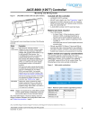
Key Features
- DIN rail-mount
- 24Vac/dc powered
- Niagara 4 area controller
- ARM® Cortex™-A8 1Ghz processor
- 1GB DDR3 SDRAM
- 2Mb (megabit) Serial FRAM
- 4GB microSD Flash memory
- Two 10/100Mbit Ethernet ports
- Two electrically isolated RS485 ports
- 802.11a/b/g/n WiFi adapter

