advertisement
 Mounting and Wiring Guide | Manualzz")
Mounting
Environmental requirements
Inserting or removing the MicroSD card
Prerequiste:
All power to the controller must be removed
(see previous
). If the unit is currently running, see
“Initiating a controller shutdown,” page 8.
Note the controller must also be unmounted from any DIN rail or screw tab mounting, as accessing the card uses space
behind the mounting base. See Figure 3 on page 2.
1.
Carefully slide the plastic microSD card shutter open.
The shutter should remain captive in the base, revealing the microSD card socket.
2.
To insert the microSD card, slide it into card carrier, label side up, until the spring catch engages.
If properly inserted, the card is behind the shutter track.
3.
To remove the microSD card, push it in, until the spring release pushes it partially out of the card carrier. Grasp the card, pull it completely out of the unit and store it in a static free protective case.
4.
Carefully slide the card shutter back over the card carrier opening, until it clicks in place. When properly closed, the shutter should not protrude behind the mounting base.
NOTE:
Data on the microSD card is encrypted. If you swap in a card from a previously configured unit, you must change the JACE-8000 system passphrase on the platform to match the passphrase on the new microSD card. See JACE-8000 Niagara 4 Install and
Startup Guide for details.
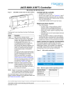
Mounting
Mount the controller in a location that allows clearance for wiring, servicing, and module removal.
Figure 4 Mounting dimensions of controller and option modules.
7.05" (179)
6.38" (162)
2.26"
(57.5)
2.17" (55)
2.13" (54)
4.33" (110)
9.53" (242)
12.00" (305)
14.49" (368)
16.97" (431)
Environmental requirements
NOTE:
This product is for indoor use only, altitude to
2,000m (6,562 ft.).
Ambient conditions must be within the range of:
•
Operating Temperature: -20°C to 60°C (-4°F to 140°F).
Storage Temperature: -40°C to 85°C (-40°F to 185°F).
•
Relative humidity: 5% to 95% non-condensing.
Pollution Degree 3
•
Supply (mains) voltage requirements are as follows:
– Allowable voltage fluctuation +/- 10%,
•
For a unit mounted inside an enclosure, ensure that the enclosure is designed to keep the unit within its required operating temperature range (considering a 24-watt dissipation by the controller). This is important if the controller is mounted inside an enclosure with other heat-producing equipment.
•
Do not mount the unit:
– in an area with excessive moisture, corrosive fumes, or explosive vapors.
– where vibration or shock is likely to occur.
– in a location subject to electrical noise, such as in the proximity of large electrical contactors, electrical machinery, welding equipment, and so on.
JACE-8000 Controller (12977) Mounting and Wiring Guide
December 15, 2015
3
advertisement
Key Features
- DIN rail-mount
- 24Vac/dc powered
- Niagara 4 area controller
- ARM® Cortex™-A8 1Ghz processor
- 1GB DDR3 SDRAM
- 2Mb (megabit) Serial FRAM
- 4GB microSD Flash memory
- Two 10/100Mbit Ethernet ports
- Two electrically isolated RS485 ports
- 802.11a/b/g/n WiFi adapter

