advertisement
▼
Scroll to page 2

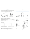
‐ 0MNACCMC8ENQB ‐
‐ 0MNACCMC8ENQB ‐
PROFIBUS CONFIGURATION SWITCHES
QUICK START MULTICOM 411
The configuration switches are used to set the PROFIBUS node address. Remove the plastic hatch to configure the switches (see
image below). Note that the node address cannot be changed during runtime, i.e. the gateway requires a reset for changes to have
effect.
PRESENTATION
The configuration is done using two rotary switches as follows: Node Address = (Switch B x 10) + (Switch A x 1)
Note: When removing the hatch and configuring the switches, avoid touching the circuit boards and components.
IN THE BOX
Example:
If the node address should be 42:
set switch A to “2” and switch B to “4”.
MultiCOM 302 board
PROFIBUS DP Gateway
CONNECTION CABLE MULTICOM 302 ↔ PROFIBUS DP GATEWAY
DB9 male
PIN
connect
to
RJ-45
PIN
5
↔
↔
↔
2
9
8
EXTERNAL VIEW
3
4
PROFIBUS Connector
NOTE: Use a twisted pair to connect PIN #9 and #8 of DB9 to PIN #3 and #4 of RJ-45
Configuration Switches
DIN‐RAIL MOUNTING
Status LEDs
Reserved
MultiCOM 302 Connector
To snap the gateway on, first press it downwards (1) to
compress the spring in the DIN-rail mechanism, then push
it against the DIN-rail as to make it snap on (2).
To snap the gateway off, push it downwards (1) and pull it out
from the DIN-rail (2), as to make it snap off from the DIN-rail.
For additional informations, please download User Manual and GSD file from manufacturer’s website.
4
Power Connector
DIN-rail Connector
1
Connection cable between MultiCOM 302
and PROFIBUS DP Gateway
‐ 0MNACCMC8ENQB ‐
‐ 0MNACCMC8ENQB ‐
MULTICOM 302 JUMPER AND DIP SWITCHES SETTINGS
PROFIBUS DP GATEWAY CONNECTORS AND LEDS
PROFIBUS CONNECTOR
1
2
PIN
Housing
Shield
1, 2, 7, 9
-
Signal
Description
Bus cable shield, connected to PE
-
3
B-Line
Positive RxD/TxD (RS485)
4
RTS1
Request To Send
5
GNDBUS2
Isolated GND from RS-485 side
6
+5V BUS2
Isolated +5 V output from RS-485 side (80 mA max)
8
A-Line
Negative RxD/TxD (RS485)
5
1
9
6
(female)
May be used by some devices to determine the direction of transmission
Used for bus termination; may also be used to power optical transceivers (RS485 to fibre optics)
POWER CONNECTOR
PIN
Description
1
+24 VDC (300 mA required)
2
GND
1
2
Note: no power supply is provided with the device.
INSTALLATION
MULTICOM 302 CONNECTOR
PIN
1, 2, 3, 4, 6, 7
Description
5
Signal Ground
8
RS485+
9
5
1
-
9
RS485-
1.
Remove the cover of the UPS expansion slot by removing the two retaining screws.
2.
Insert MultiCOM 302 in the slot.
3.
Fix the cover provided using the screws previously removed.
4.
Connect the PROFIBUS DP Gateway to the MultiCOM 302 using the cable provided with the device.
NOTE: if necessary, you can also use another cable realized in accordance with the specifications (see Connection cable
MultiCOM 302 ↔ PROFIBUS DP Gateway).
6
(female)
STATUS LEDS
#
1 - PROFIBUS Online
2 - PROFIBUS Offline
State
Status
Off
Not online
Green
Online
Off
Not offline
Red
Offline
3 - (Not used)
-
-
Off
No diagnostics present
4 - PROFIBUS
Diagnostic
Red, flashing 1Hz
Error in configuration
Red, flashing 2Hz
Error in user parameter data
Red, flashing 4Hz
Error in initialization
5 - Subnet Status
6 - Device Status
Off
Power off
Green, flashing
Running correctly, but errors occurred
Green
Running
Red
Subnet error
Off
Power off
Alternating Red/Green
Invalid or missing configuration
Green
Initializing
Green, flashing
Running
Red
Red, flashing
Bootloader mode
Contact support department
2
5.
Set the PROFIBUS node ID (see Configuration Switches).
6.
Connect the PROFIBUS DP Gateway to the PROFIBUS DP Network.
7.
Connect the power cable and apply power.
3
advertisement
Key Features
- PROFIBUS DP Gateway
- Node Address Configuration
- Status LEDs
- DIN-rail Mounting
- Real-time Monitoring
- UPS Integration
Related manuals

Frequently Answers and Questions
How do I set the PROFIBUS node address?
The node address is set using two rotary switches. The address is calculated as (Switch B x 10) + (Switch A x 1).
What are the different status LEDs and what do they indicate?
There are 6 status LEDs: PROFIBUS Online, PROFIBUS Offline, PROFIBUS Diagnostic, Subnet Status, Device Status, and Bootloader Mode. Each LED indicates a specific operational state of the gateway.
How do I connect the MULTICOM 411 to the PROFIBUS DP network?
Connect the PROFIBUS DP Gateway to the MultiCOM 302 using the cable provided. Then, connect the gateway to the PROFIBUS DP network.
Download
PDF
advertisement