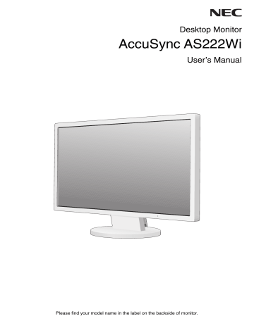
Contents. NEC AccuSync AS222Wi
Add to My manuals17 Pages
NEC AccuSync AS222Wi is a high-performance desktop monitor designed to provide users with a clear and immersive viewing experience. With its advanced LCD panel, users can enjoy stunning visuals with crisp details and vibrant colors, making it ideal for both professional and casual use. Its adjustable stand allows for flexible positioning, ensuring optimal viewing angles and ergonomic comfort. Additionally, the monitor's multiple connectivity options, including HDMI and DisplayPort, enable seamless integration with various devices, making it a versatile solution for various setups.
advertisement

Contents
Your new NEC AccuSync LCD monitor box* should contain the following:
• AccuSync LCD monitor with tilt base
• Video Signal Cable (15-pin mini D-SUB male to 15-pin mini D-SUB male)
Setup
Manual
Setup Manual Cable Holder Power Cord* 1 Video Signal Cable Base Stand
* Remember to save your original box and packing material to transport or ship the monitor.
*1 Type of power cord included will depend on the where the LCD monitor is to be shipped.
Quick Start
To attach the Base Stand to the LCD Stand:
1. Attach the Base Stand to the Stand. The locking tabs on the Base Stand should fi t into the hole on the Stand (Figure S.1).
To attach the AccuSync LCD monitor to your system, follow these instructions:
1. Turn off the power to your computer.
2. For the PC or MAC with DVI digital output: Connect the DVI signal cable
(not included) to the connector of the display card in your system (Figure A.1).
Tighten all screws.
For the PC with Analog output: Connect the 15-pin mini D-SUB signal cable to the connector of the display card in your system (Figure A.2). Tighten all screws.
For the MAC: Connect the Macintosh cable adapter (not included) to the computer and then attach the 15-pin mini D-SUB signal cable to the Macintosh cable adapter
(Figure A.3). Tighten all screws.
NOTE: Some Macintosh systems do not require a Macintosh cable adapter.
Stand
AccuSync LCD monitor
(Base Stand not connected)
Figure S.1
Base Stand
DVI Signal Cable (not included)
Figure A.1
Figure A.2
Macintosh Cable Adapter
(not included) Figure A.3
English-5
3. Connect the 15-pin mini D-SUB of the video signal cable to the appropriate connector on the back of the monitor
(Figure B.1).
4. Connect one end of the power cord to the monitor and the other end to the power outlet. Place the Video Signal Cable and power cord to the Cable Holder (Figure C.1).
NOTE: Adjust the position of the cable within the Cable Holder to avoid damage to the cable or monitor.
NOTE: Please refer to Caution section of this manual for proper selection of power cord.
5. Turn on the monitor with the bottom power key and the computer (Figure D.1).
The model name is on the label.
Power cable
Input (VGA)
Input (DVI)
Rating label on the back of the display.
Figure B.1
Figure C.1
Figure D.1
6. No Touch Auto Adjust automatically adjusts the monitor to optimal settings upon initial setup for most timings.
For further adjustments, use the following OSD controls:
• Auto Adjust Contrast (Analog input only)
• Auto Adjust (Analog input only)
Refer to the Controls section of this User’s Manual for a full description of these OSD controls.
NOTE: If you have any problem, please refer to the Troubleshooting section of this
Power Key
Tilt
Grasp both sides of the monitor screen with your hands and adjust the tilt as desired
(Figure TS.1).
Remove Monitor Stand for Mounting
To prepare the monitor for alternative mounting purposes:
Figure TS.1
1. Disconnect all cables.
2. Place monitor face down on a non-abrasive surface (Figure R.1).
3. Remove the 4 screws connecting the monitor to the stand and remove the stand as indicated (Figure R.2).
The monitor is now ready for mounting in an alternative manner.
4. Connect the AC cord and signal cable to the back of the monitor (Figure R.3).
5. Reverse this process to re-attach stand.
NOTE: Use only VESA-compatible alternative mounting method.
NOTE: Handle with care when removing monitor stand.
Figure R.1
Non-abrasive surface
Figure R.2
English-6
Figure R.3
Remove the Base Stand
NOTE: Always remove the Base Stand when shipping the LCD.
1. Place monitor face down on a non-abrasive surface (Figure R.1).
2. Using your thumb, press the button to unlock (Figure R.4).
3. With the button pressed in, pull off the Base Stand (Figure R.4).
Connect a Flexible Arm
This LCD monitor is designed for use with a fl exible arm.
Figure R.4
Please use screws (4pcs) as shown in the picture when installing. To meet the safety requirements, the monitor must be mounted to an arm which, guaranties the necessary stability under consideration of the weight of the monitor.
Caution: Use ONLY the screws (4 pcs) that were removed from the stand or the specifi ed screws (Figure F.1) to avoid damage to the monitor or stand.
To meet the safety requirements, the monitor must be mounted to an arm which guaranties the necessary stability under consideration of the weight of the monitor. The LCD monitor should only be used with an approved arm
(e.g. TUEV GS mark).
NOTE: Tighten all screws (recommended Fasten Force: 98 - 137 N•cm).
12 mm
M4
4 x 12 mm with lock washer and fl at washer
Thickness of Bracket
(Arm) 2.0 ~ 3.2 mm
100 mm
Tighten all screws
100 mm
Figure F.1
Specifi cations
4-SCREWS (M4)
(MAX depth: 10 mm)
If use other screw, check depth of hole.
Weight of LCD assembly: 3.7 kg (MAX)
English-7
advertisement
Related manuals
advertisement