advertisement

RELEASED: 10/2/2006
Page 5
COMMUNICATI0NS
HSD SERIES OPERATION AND MAINTENANCE
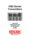
1 THE HSD SERIES TRANSMITTER 0VERVIEW
1.1 Introduction:
The EMCEE
HSD Series
TM transmitter is a modular, frequency agile, format agile, selfcontained S-Band broadcast transmitter that is designed to provide up to 400 Watts peak power or 100 Watts average power on any FCC or CCIR specified channel from 2500MHz to 2700MHz. The transmitter will accept either a digital input or a composite analog input.
The transmitter is also available configured for multi-channel operation. To provide maximum performance and reliability, the HSD Series
TM Transmitter is completely solidstate. The transmitter design includes IF linearity pre-correction, which minimizes the inchannel intermodulation products; oscillator and converter circuits optimized for very low phase and FM noise, which allows for depth of modulation up to 256QAM; automatic internal or external synthesizer lock, for use with phase-locked systems; and infinite tuning, by 1 MHz steps, across the entire band . The transmitter is designed to provide configurable and upgradeable output power, requiring only a 6RU rack footprint. It features minimum weight and low power consumption; and employs comprehensive indication, control, and protection circuitry. To provide additional reliability, the
HSD Series
TM transmitter system is designed to utilize a redundant N+1 power supply and power distribution system (HSD
PLUS
). The transmitter will facilitate either digital or analog transmission, and is compatible with all world analog transmission formats.
Each transmitter is composed of a Power Supply assembly, Up-Converter Assembly, one or more 12.5 watt Final Amplifiers, and an optional Control/Status interface. The
Control/Status interface allows the unit to be remotely controlled via computer and graphically shows the status of the transmitter; aiding the operator during turn-on, operation and maintenance.
Optional output filters are available for additional suppression of out of channel products.
The HSD Transmitters are available in the following output power configurations:
¾
¾
HSD-250 1
HSD-1250/HSD-1250
¾ HSD-2500/HSD-2500
PLUS
PLUS
¾ HSD-3750/HSD-3750
PLUS
¾ HSD-5000/HSD-5000
PLUS
¾ HSD-10000/HSD-10000
PLUS
10 Watt Peak/2.5 Watt Average Power
50 Watt Peak/1-12.5 Watt Average Power
100 Watt Peak/2-25 Watt Average Power
150 Watt Peak/3-37.5 Watt Average Power
200 Watt Peak/5-50 Watt Average Power
400 Watt Peak/10-100 Watt Average Power
The HSD-XXX
PLUS
configurations feature N+1 redundant power supplies.
1 The HSD-250 is used as the Up-Converter/Driver assembly for all other models.
This is an unpublished work protected by the United States copyright laws and is proprietary to EMCEE Communications.
Disclosure, copying, reproduction, merger, translation, modification, enhancement or use by anyone other than authorized employees or licensees of EMCEE Communications without the prior written consent of EMCEE Communications is strictly prohibited.
Copyright © 2006 EMCEE Communications. All rights reserved.
This copyright notice should not be construed as evidence of publication.
advertisement
