advertisement

Chapter
8
Using Reference and Variable View Tables
VersaPro provides two View Tables for monitoring the real-time values and states of elements in the PLC:
•
The Variable View Table allows you to group important variables into a window for online viewing.
•
The Reference View Tables allows you to group important references into a window for online viewing.
Multiple View Tables may be open at once.
Chapter Contents
•
Overview of Reference View Tables (RVT) and Variable View Tables (VVT)
•
Information on creating and managing data in the view tables.
GFK-1670C 8-1
8
Variable View Tables – Overview
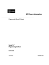
Variable View Tables (VVTs) allow you to monitor the states of variables. A folder may have zero or more mixed-type VVTs. VVTs and VVT entries can be cut and copied, and dragged and dropped between folders.
An example of a VVT is shown below.
Scope:
Shows variable scope: Global or
Local:block.
Name:
Displays variable name, which may be userdefined or match the
Reference Address.
Address:
Displays PLC reference address for each variable.
Value:
Displays PLC online value if you are connected to the PLC, with logic equal, and monitoring active.
Only the Name column may be edited. All other columns are read-only.
The Value column is blank until the Folder is on-line and equal. The value cell displays
“****” for variables that have no assigned reference address.
If the cell is too narrow to display the online value, the cell will display ####.
8-2 VersaPro™ Programming Software User's Guide – November 2000 GFK-1670C
Reference View Tables – Overview
Reference View Tables (RVTs) contain a list of references that can be monitored and updated in real-time. A folder can have zero or more reference tables. RVTs can be cut and copied and dragged and dropped between Folders. More than one Reference Area can be entered into a single RVT.
The number of entries contained in an RVT does not affect the performance of the RVT.
Performance is affected only by the number of entries that are displayed and have to be updated in the view.
Example RVTs are shown below.
Starting address
Format of selected address
Selected address
8
Display format can be selected for individual cells
GFK-1670C
All Reference Addresses are displayed that begin with the closest byte offset smaller than or equal to the starting address you enter and finish eight columns later (Ten columns of data are displayed for %R, %AI, and %AQ reference addresses.) The amount of data displayed in the columns depends on the format.
Note:
Upon opening a folder created with VersaPro 1.00, the Reference View
Tables will be converted to the new format. However, table format selections will be reset to the defaults.
Chapter 8 Using Reference and Variable View Tables 8-3
8
Creating New Reference and Variable View Tables
New Variable View Tables and Reference View Tables are created from the folder browser CSM or the File menu. You can have multiple view tables in your folder.
To create a new Reference View Table:
1
.
From the Folder Browser, click the right mouse button and choose New, View Table,
Reference View Table (or select the File menu and choose New, View Table,
Reference View Table). The New Reference View Table dialog box will appear:
2
.
Enter a name for the RVT. Click OK to accept.
3
.
The new RVT is created and displays in the folder window. The new RVT icon is added to the Folder Browser with the RVT name.
Note:
Offsets columns are not populated until you are connected to the PLC and have enabled Monitoring.
To create a Variable View Table:
1
.
From the Folder Browser, click the right mouse button and choose New, View Table,
Variable View Table (or select the File menu and choose New, View Table, Variable
View Table). The New Variable View Table dialog box will appear:
8-4
2
.
Enter a name for the VVT. Click OK to accept.
3
.
The new VVT is created and displays in the folder window. The new VVT icon is added to the Folder Browser with the VVT name.
VersaPro™ Programming Software User's Guide – November 2000 GFK-1670C
Customizing View Table Display
You can customize font selection and color for VVTs and RVTs. Perform the following steps to customize the display:
4
.
From the Folder Browser, click the Tools menu and select Options. The Options dialog box will appear. Select the Display tab.
8
5
.
You can change the font selection and change the color used for the display of online values.
•
To modify the settings for the RVT, set the Category to RVT and make the desired changes. Click OK to accept.
•
To modify the settings for the VVT, set the Category to VVT and make the desired changes. Click OK to accept.
GFK-1670C Chapter 8 Using Reference and Variable View Tables 8-5
8
Changing Reference View Table Display Format
Your selections of Byte, Word, or Dword governs how much data is displayed in each cell. Formatting for an RVT occurs on a table, not a row, basis. Perform these steps to change the display format for a RVT:
1
.
Open the RVT.
2
.
Select the View menu and choose Format View Table. The Format Display dialog box will appear.
8-6
3
.
Select the Grouping and Display Format which suits your application needs:
•
Grouping Field
Byte (each cell contains 8 bits)
Word (each cell contains 16 bits)
Dword (each cell contains 32 bits)
•
Display Format
Binary
Hex
Octal
Unsigned Decimal
Signed Decimal
Real (Only available when Dword is selected)
Scientific Notation (Only available when Dword is selected).
You can change the display format of an individual cell by selecting the cell and choosing
Display Format from the context-sensitive menu.
VersaPro™ Programming Software User's Guide – November 2000 GFK-1670C
Customizing Variable View Table Display Format
You can customize the value display format for Variable View Tables. To change the display format for online values, perform the following steps:
1
.
Open the VVT. Select row containing the variable where you want to change the display format.
2
.
Click the right mouse button and select Display Format from the CSM..
8
3
.
Change the display to suit your application requirements. The format is changed for the variable selected.
Note:
If the value displays ####, increase the width of the value column to see the online value.
GFK-1670C Chapter 8 Using Reference and Variable View Tables 8-7
8
Adding Elements to a View Table
You can add logic elements (references or variables) to a View Table for online monitoring.
You may be either off-line or on-line when you add a new entry to a Variable View Table.
If you are on-line and equal to the PLC, the new variable’s data updates automatically.
Adding an Element by Direct Entry to a VVT
1
.
From the Folder Browser, open a VVT.
2
.
Select the Name field on a blank line in the VVT.
3
.
Select a variable using the Name field’s drop-down list, or type in a valid variable name.
4
.
Press Enter, or select another field. The entered variable and corresponding columns
(address and scope) are displayed in the VVT.
Valid VVT Variable Entries
Valid variable entries may consist of any of the following:
• name
• address (If only an address is typed into the Name field, that address will appear in both the Name and Address fields.)
• name, address (The Scope will default to global.)
• name, g (The scope will be assigned as Global.)
• address, g
• name, address, g
• name, local: scope (Scope is the block to which the variable should be locally assigned. For example, to assign a variable with the name "A" locally to a block named "B", type "A,local:B" in the Name field.)
• address, local: scope
• name, address, local: scope
The length of a variable in a View Table reflects the length that was entered into the
Variable Declaration Table. Changes to length may only be made through the VDT.
Information may not be entered directly into the Address or Scope fields.
8-8 VersaPro™ Programming Software User's Guide – November 2000 GFK-1670C
Adding an Address to a Reference View Table
1
.
From the Folder Browser, open an RVT.
2
.
On a blank line, select the Reference Address column. Type a reference address in one of the following formats (%I00001 , 1I)
3
.
Press Enter, or select another field. The reference and corresponding columns are displayed in the RVT.
Valid RVT Entries
•
Word Memory areas (R, AI, AQ) begin with the address you enter.
•
The same reference address may be entered and displayed more than once.
•
If a value is too large to display in the current cell width, “#####”s appear until you increase the column width so that the entire value can be displayed.
•
Valid offsets range from 0-99999. If an entered offset exceeds the maximum, an error message appears informing you of the maximum value and the fact that it has been exceeded. Monitoring within an RVT can not take place until all offsets are determined to be within the limits of the PLC.
•
If an offset is valid, but data is not available, a 0 displays. If the offset is not valid, the cell remains blank.
Adding a Range to a Reference View Table
1
.
Open an RVT by double-clicking on it in the Folder Browser.
2
.
On a blank line, select the Reference Address column .
3
.
Enter the first address in the range, a comma, and then the last address in the range.
Multiple reference addresses must be separated by commas. Entering an invalid multiple range Reference Address results in an error.
•
The same reference address range may be entered and displayed more than once.
•
Valid offsets range from 0-99999. If an entered offset exceeds the maximum, an error message appears informing you of the maximum value and the fact that it has been exceeded. Monitoring within an RVT can not take place until all offsets are determined to be within the limits of the PLC.
•
If an offset is valid, but data is not available, a 0 displays. If the offset is not valid, the cell remains blank.
8
GFK-1670C Chapter 8 Using Reference and Variable View Tables 8-9
8
Modifying Information in a View Table
VersaPro allows you to edit the variables contained in a View Table by changing the
Name of a variable. Changing the Name in a View Table selects a different variable from the VDT, and replaces the existing variable in the View Table. True changes to a Name must be made in the VDT.
To write a value to a reference, select the cell corresponding to the reference in the VVT or RVT, and type the new value. (You can also place the view table in edit mode by double clicking in the cell, pressing F10 or choosing Write from the PLC menu.)
8-10 VersaPro™ Programming Software User's Guide – November 2000 GFK-1670C
Editing Operations in View Tables
Using cut, copy, paste in a VVT
1
.
Open the VVT from which you wish to cut a variable entry or entries.
2
.
Select at least one cell within each row that you wish to cut.
3
.
Choose Cut or Copy from the Edit menu, click the Cut or Copy button, or press Ctrl + X to cut or Ctrl + C to copy.
4
.
All rows entirely selected are removed from the VVT and placed on the clipboard in
VersaPro list format (not as text), and other rows shift to fill the cut space.
5
.
If you want to insert the variables between existing variables on the destination VVT, rather than overwrite existing variables, select any cell in the row beneath the desired insertion point.
6
.
If you want to overwrite existing variables, select the rows that you wish to overwrite.
7
.
Choose Paste from the Context-Sensitive or Edit menu, click the Paste button , or press Ctrl + V. If the variables are inserted, they appear in a new row above the row in which a cell is selected, and are appended to any other affected table(s). If the variables overwrite previously-existing variables, they appear in the position of those variables.
Details on Cutting and Copying
•
Variables cut or copied from a VVT can be pasted only in the same or another view table. They can also be pasted between view tables in different folders.
•
Cutting or copying a variable in a VVT does not affect the VDT.
•
Variables can be cut or copied during monitoring.
•
Text can be pasted into the name field only when it is in edit mode.
Note:
Only entire rows may be cut. Selecting any cell in a row, and then cutting, results in cutting the entire row.
8
GFK-1670C Chapter 8 Using Reference and Variable View Tables 8-11
8
Details on Pasting
•
If more variables reside on the clipboard than have been selected to be overwritten, the selected variables are overwritten and the remaining clipboard variables are inserted into the table.
•
If fewer variables reside on the clipboard than have been selected to be overwritten, as many of the selected variables as possible are overwritten, and the rest are deleted.
•
When you paste to a second instance of a VVT, a new variable is created in the VDT.
•
If collisions occur when creating variables in the VDT, an error message appears describing the problem.
•
Click OK. A dialog appears allowing you to correct the problem.
•
Correct the problem. Row validation continues for other variables. If you cancel, the entire paste is cancelled.
To drag and drop-cut in a VVT:
1
.
Open the VVT from which you wish to cut a variable entry or entries.
2
.
Select at least one cell within each row that you wish to cut.
3
.
Position the mouse arrow over the selected row.
4
.
Press and hold the primary mouse button.
5
.
Move the variable or cell to the appropriate area.
6
.
A graphical representation of the selected area is displayed to indicate a selection is being dragged. This representation changes dynamically when you drag between two instances of the VVT which have different cell dimensions.
7
.
To drop the selection, release the mouse button. If it is valid in the new location, the selected variable or cell is removed from the original position and placed in the new position. If it is not valid, the drag and drop operation is cancelled.
To drag and drop-copy in a VVT:
1
.
Open the VVT from which you wish to cut a variable entry or entries.
2
.
Select at least one cell within each row that you wish to cut.
3
.
Position the mouse over the selected variable or cell.
4
.
Press and hold the Ctrl key.
5
.
Press and hold down the primary mouse button.
6
.
Move the variable or cell to the appropriate area.
8-12 VersaPro™ Programming Software User's Guide – November 2000 GFK-1670C
7
.
A graphical representation of the selected area is displayed to indicate a selection is being dragged. This representation changes dynamically when you drag between two instances of the VVT which have different cell dimensions.
8
.
To drop the selection, release the mouse button. If it is valid in the new location, the selected variable or cell is copied from the original position and placed in the new position. If it is not valid, the drag and drop operation is cancelled.
8
Details on Dragging and Dropping in a VVT
•
Selections may be dropped on any part of a row.
•
If a section is dropped on the last row of the VVT that would go beyond the last row of the table, new rows are created to accommodate the drop.
•
Variables can be entered more than once within a VVT.
•
If a selection is dropped that would go beyond the last row of the VVT, new rows are created to accommodate the drop.
•
When a selection is dropped, it overwrites the existing cells.
•
VersaPro does not allow dragging and dropping a discontinuous set of cells.
•
When you drop to a second instance of a VVT, a new variable is created in the VDT.
•
If collisions occur when creating variables in the VDT, an error message appears describing the problem.
•
Click OK. A dialog appears allowing you to correct the problem.
•
Correct the problem. Row validation continues for other variables. If you cancel, the entire paste is cancelled.
Saving View Tables
It is important to save changes to both RVT and VVTs when editing. This section describes how to save View Tables.
Online values are not saved with view tables. Online values are maintained in the PLC and are displayed in the view tables.
To save changes when editing a view table, Select the File menu and choose Save, or click the Save toolbar button.
GFK-1670C Chapter 8 Using Reference and Variable View Tables 8-13
8
Online Viewing
To view online values for view tables, the folder must be open and you must be connected with the PLC. In addition, the View Table window must be monitoring PLC data. To set the View Table to monitoring, click the Monitor All or Monitor Active toolbar buttons.
This section provides details about window behavior when working online and describes how to change values online.
Details about Online Viewing
•
If the value is too large to display in the current Value column cell width, "####" displays until the column width is altered.
•
Override status is displayed as an underlined value (as in both editors).
•
Overriding and toggling variables is done through the right mouse menu.
•
Array Variables (variables with a length greater than 1) display the address, scope, and value on subsequent lines under the first entry.
To Toggle or Override a Reference in an RVT
To work online in the RVT, connect to the PLC and perform the following steps to toggle and override references.
1
.
Open the RVT. Select the View menu and choose Monitoring -> All or Monitoring -
> Active Window.
2
.
Place the cursor on an offset of the reference that you want to toggle or override.
3
.
Select the PLC menu and choose Toggle, press the F12 key or click the Toggle button. . The RVT Override/Toggle Bit dialog box will appear.
4
.
To override, press the F11 key or click the Override button. The appropriate reference is toggled or overridden.
8-14 VersaPro™ Programming Software User's Guide – November 2000 GFK-1670C
To Write a Value to a Reference in an RVT
1
.
Open the RVT. Select the View menu and choose Monitoring -> All or Monitoring -
> Active Window.
2
.
Place the cursor on an offset of the reference that you want to change.
3
.
Select the PLC menu and choose Write Reference Value, or click the Write Reference
Value button. .
4
.
Enter the value. Click the OK button to accept. The value is written to the reference address in the PLC.
8
GFK-1670C Chapter 8 Using Reference and Variable View Tables 8-15
advertisement
* Your assessment is very important for improving the workof artificial intelligence, which forms the content of this project