advertisement

6 RECORDING
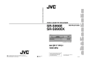
6-3 Timer Recording
[SHIFT 7] button
[RESET/CANCEL] button
VIDEO CASSETTE RECORDER
SR-S990E
REC
625
VHS
PAL
REC STOP
OPERATE
REW REVERSE PAUSE PLAY FF
FIELD REV FIELD ADV
TRACKING
– +
V. LOCK
– +
TIMER SEARCH DISPLAY LOCK CNT RESET
RESET/
CANCEL ON SCREEN
MENU
SHIFT
TIME MODE
– S E T +
EJECT OPERATE
RESET/
CANCEL
MENU
SHIFT
TIME MODE
–
ON SCREEN
S E T
+
[MENU] button
[SHIFT f] button
[TIMER] button
[SET –] button
[SET +] button
Canceling/Changing Timer Recording
Program
To stop timer programming before finishing
1
Press the [RESET/CANCEL] button.
[ The program being set is canceled.
2
Press the [MENU] button twice.
[ The normal screen mode is restored.
To cancel preset timer programs
1
Press the [TIMER] button so that the TIMER indication goes out on the display.
2
Turn on the VCR and monitor.
3
Press the [MENU] button to show the main menu screen and press the [SHIFT 7] button to select <PROGRAM
TIMER> or <HOLIDAY SET>. Then, press the [SET +/–] button.
[The <PROGRAM TIMER> or <HOLIDAY SET> menu is shown on the monitor.
4
Press the [SHIFT 7] button or [SHIFT f] button to move the cursor to the program you want to cancel.
5
Press the [RESET/CANCEL] button.
[ The specified timer recording program is canceled.
6
Press the [MENU] button twice.
[ The normal screen is restored.
To modify timer programs
1
Press the [TIMER] button so that the TIMER indication goes out on the display.
2
Turn on the VCR and monitor
3
Press the [MENU] button to show the main menu screen and press the [SHIFT 7] button to select <PROGRAM
TIMER or <HOLIDAY SET>. Then, press the [SET +/–] button.
[The <PROGRAM TIMER> or <HOLIDAY SET> menu is shown on the monitor.
4
Press the [SHIFT 7] button or [SHIFT f] button so that the section you want to change blinks.
5
Press the [SET +/–] button to change the value.
6
Press the [MENU] button twice.
[ The normal screen is restored.
To use the VCR when the Timer-Recording
Standby mode is engaged
• Press the [TIMER] button so that the TIMER indication goes out. After using the VCR, press the [TIMER] button again to engage the Timer-Recording Standby mode. The
TIMER indication will light.
• When all timer recording programs are completed, the
TIMER indication goes out.
36
6 RECORDING
6-3 Timer Recording
Notes on Timer Recording
5
If you make a mistake when programming or no program is set and the [TIMER] button is pressed, the
TIMER indication blinks for about 10 seconds and a warning buzzer sounds if <WARNING> in the
<BUZZER> menu is set to “ON”.
=
Perform programming for timer recording.
* Note that if the date is not set for holiday timer recording, the TIMER indication will not blink, the time standby mode is not engaged, and recording will not take place.
5
If programmed data overlap
When the [TIMER] button is pressed, the Timer-
Recording Standby mode is engaged and the
[OVERLAP] indication blinks for about 10 seconds, then lights.
(However, if program timer settings and holiday timer settings overlap, the [OVERLAP] indication is not shown. In this case, the holiday timer setting has priority. The [OVERLAP] indication is not shown when a daily timer recording program overlaps with another program (even during program timer setting). The program with the earlier start time has priority.)
=
Check the program contents.
(With program timer settings, the program with the earlier program time has priority.)
5
When more than one timer recording is programmed:
=
• The preset programs are executed consecutively beginning with the program with the earliest start time.
The number of the program being executed blinks.
* Program numbers are not displayed for holiday timer recording programs.
5
When the timer recording mode is engaged after the start time has passed:
When a power failure occurs within the set times and power is restored:
=
• Timer recording starts within the set times.
* If holiday timer and program timer settings overlap, the holiday timer setting has priority and starts.
* When program timer settings overlap, the program with the lower program number has priority and starts.
5
When the timer recording settings are changed during timer recording:
=
Changing the settings on the program timer setting screen or holiday timer setting screen during timer recording will have no effect. To change the settings, you must disengage the timer recording mode.
5
During timer recording
The [PAUSE] or [STOP] button has no effect.
=
Operation after pressing the [TIMER] button.
5
Timer recording
The operating mode is turned on about 20 seconds before recording starts and the VCR pauses. Recording starts about 2 seconds before the actual programmed start time.
5
If no cassette is loaded
The TIMER and [ ] indications blink and a warning buzzer sounds if <WARNING> in the <BUZZER> menu is set to “ON”.
=
Load a cassette with safety tab. Cassettes with no tab are ejected.
5
When the tape ends during timer recording:
=
The cassette tape is ejected.
When a cassette with safety tab is loaded, the timer recording re-starts.
* However, if timer recording is executed in the Repeat
Record mode, the cassette tape is not ejected at the tape end and repeat recording continues.
5 When the recording speed of program timer or holiday timer is set as L12/L24.
The cassette is ejected when a VHS cassette is loaded and the [TIMER] button is pressed.
=
• Insert an S-VHS cassette, or switch to a recording speed other than L12/L24.
37
6 RECORDING
6-4 Alarm Recording
Alarm recording functions during timelapse recording. When an alarm signal is input to the rear panel’s ALARM IN terminal, an index code is recorded on the tape and the VCR automatically switches to the 3H (SP) mode for realtime recording of the alarm situation. Normal timelapse recording is restored after the preset alarm recording duration has passed.
* Alarm recording will not start from the Pause mode.
“AL” indication
625
VHS
PAL
REC STOP
OPERATE
REW REVERSE PAUSE PLAY FF
FIELD REV FIELD ADV
TRACKING
– +
V. LOCK
– +
TIMER SEARCH DISPLAY LOCK CNT RESET
RESET/
CANCEL ON SCREEN
MENU
SHIFT
TIME MODE
– S E T
+
VIDEO CASSETTE RECORDER
SR-S990E
REC
EJECT OPERATE
AL
TIME MODE
5
Menu switches are provided for alarm recording duration, buzzer ON/OFF in alarm recording, and
Forced Stop mode ON/OFF at tape end.
5
During alarm recording, the [AL] indication is lit on the
VCR and the [ALARM] indication is lit on the monitor display. After alarm recording is complete, the “AL” indication blinks on the display to show that an alarm signal has been input.
* If the alarm recording function is activated a hundred times a day or more, a malfunction may occur because the guaranteed range is exceeded.
If you want to use this unit more than a hundred times a day, set the recording speed mode to 3H, L12H or
L24H and perform regular maintenance, replacing parts as necessary.
On-screen
"ALARM" indication
Display "AL" indication
Extinguished
Extinguished
Record mode
Shown
Lit
Timelapse mode
Timelapse recording
3H (SP)
Alarm recording
Alarm signal input
Extinguished
Blinking
Shown
Lit
Timelapse mode
Timelapse recording
3H (SP)
Alarm recording
Alarm signal input
Extinguished
Blinking
Timelapse mode
Timelapse recording
* An index code (VISS) is recorded at the start point of the alarm recording as an alarm cue signal.
* During alarm recording, a +12 V signal is output from the rear panel’s ALARM REC OUT terminal.
* If a new alarm signal is input during alarm recording, alarm recording restarts from that point.
38
6 RECORDING
6-4 Alarm Recording
Preparation
Connect an alarm sensor to the rear panel’s alarm input terminal.
1
Press the [OPERATE] button to turn the operating mode on.
2
Open the main menu’s <ALARM/SENSOR MODE> and set the alarm recording-related menu switches.
1 REC MODE
Set to “ALARM” or “ALL” to activate alarm recording.
• When set to “ALL”, both alarm recording and sensor recording will be performed.
• The [ALARM] indication lights on the display.
2 DURATION
Set the alarm recording duration to 5 sec., 10 sec., 15 sec., 30 sec., 60 sec., 120 sec., 180 sec., TAPE END
(to tape end) or MANUAL (for as long as alarm signals are input).
* When the alarm recording time is set to “MANUAL”, the alarm cue signal (index code) will not be recorded correctly if alarm input lasts for less than 5 seconds.
* When alarm recording duration is set with an external switcher, set the alarm recording duration to
“MANUAL”.
3 TAPE END MODE
Selects whether or not the Stop mode is forcibly engaged when the tape ends even if there is an alarm recording during recording.
• When set to “STOP”, the Stop mode is engaged at tape end even if repeat recording or auto rewind is set.
• When set to “OFF”, VCR operation is determined by the repeat recording or auto rewind setting.
3
Set the other menu switches.
5
Setting the alarm buzzer
Set the menu switch <AL/SENSOR IN> in
<BUZZER> to “ON” to sound the alarm buzzer during alarm recording.
5
Setting the on-screen brightness and display items
Select the monitor display setting with the menu switch.
On-screen information is recorded together with the video signals.
You can change the on-screen display position with the [ON SCREEN 7/f] buttons on the front panel.
ALARM/SENSOR MODE screen
2
3
*
1
*
1
2
6
7
3
5
*
.
.
.
.
.
*
.
.
.
.
C
[
*
S
*
R
E X
*
I
R
D
A
R
R
N
A
E
U
T A
U
E
E
C
R
T
T
L
P
T
P
P
[
/
*
*
A
*
A
E
O
E
E
S
E
R
X
R
T A
R
M
T
*
*
A
A
E
M
O
I
D
O
E
R
T
E
T
C
P
N
E
*
*
I
/
/
*
*
E
S
E
N
D
W
P
R
E
*
E
S
X
*
N
E
E N
*
*
*
*
*
*
M
*
L A
E C
T
*
D
N
S
*
*
O
*
Y
*
*
*
*
D
O
*
*
D
*
*
*
M
*
*
*
R
*
*
E
*
*
*
*
*
*
*
*
O
*
*
*
*
*
*
D
*
E
*
*
*
M
*
*
*
*
*
*
*
*
*
O
*
*
*
*
*
*
*
]
*
*
*
*
*
*
*
*
A
6
*
*
*
*
*
*
*
*
*
*
*
O
N O R M A L
* *
D E
*
]
L
0
O
*
A
S
O
O
O
O
*
F
F
*
R
E
F
F
F
F
*
F
F
*
M
C
F
F
F
F
Set to “ALARM” or “ALL”.
4
Select the timelapse recording mode with the [TIME
MODE +/-] button on the front panel.
[ The selected recording speed mode is shown on the
VCR’s display and on the monitor.
5
Follow the procedure described in “Recording Basic
Operation” on page 30.
6
When an alarm signal is input to the rear panel’s
[ALARM IN] terminal, alarm recording is executed in accordance with the specified settings.
7
To stop alarm recording and clear the [ALARM] indication, press the [RESET/CANCEL] button.
• If the [RESET/CANCEL] button is pressed when the
[AL] indication is lit (during alarm recording), alarm recording stops, the [AL] indication goes out, and timelapse recording is restored. If the alarm buzzer is on, the buzzer sound also stops.
• If the [AL] indication blinks and the [RESET/CANCEL] button is pressed, the [AL] indication goes out.
8
The alarm input data can be checked in the main menu’s <OTHER> menu (refer to page 21).
Display the alarm list screen and press the [RESET/
CANCEL] button to reset the alarm input data.
* There may be some picture distortion at the start or end of an alarm recording. This is not a malfunction.
39
advertisement
* Your assessment is very important for improving the workof artificial intelligence, which forms the content of this project
Related manuals
advertisement