advertisement
ADV8003 Hardware Manual
It is possible to use the subaddresses auto-increment feature, which allows data to be accessed from the starting subaddress. A data transfer is always terminated by a stop condition. The user can also access any unique subaddress register on a one-by-one basis without having to update all the registers.
Stop and start conditions can be detected at any stage during the data transfer. If these conditions are asserted out of sequence with normal read and write operations, these cause an immediate jump to the idle condition. During a given SCLK high period, the user should issue only one start condition, one stop condition, or a single stop condition followed by a single start condition. If an invalid subaddress is issued by the user, the ADV8003 does not issue an acknowledge and returns to the idle condition.
If the user exceeds the highest subaddress in auto increment mode, the following actions are taken:
• In read mode, the highest subaddress register contents continue to be output until the master device issues a no acknowledge.
This indicates the end of a read. A no acknowledge condition is where the SDA line is not pulled low on the ninth pulse.
• In write mode, the data for the invalid byte is not loaded into any subaddress register. A no acknowledge is issued by the
ADV8003 and the part returns to the idle condition.
Figure 12: Bus Data Transfer
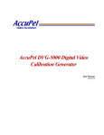
Figure 13: Read and Write Sequence
1.6.
CONFIGURING THE ADV8003
The ADV8003 requires a number of configuration settings for each mode of operation. To ensure the part is correctly configured, refer to either the recommended settings configuration script (supplied with the ADV8003 evaluation software) or the reference software driver.
Failure to follow these recommended settings will result in the part not operating to its optimum performance.
Rev. B, August 2013 68
advertisement
* Your assessment is very important for improving the workof artificial intelligence, which forms the content of this project
Related manuals
advertisement
Table of contents
- 2 TABLE OF CONTENTS
- 2 Understanding the ADV8003 Hardware Manual 10
- 2 1. Introduction to the ADV8003 15
- 2 2. ADV8003 Top Level Control 69
- 3 3. Video Signal Processing 144
- 5 4. On Screen Display 208
- 5 5. Serial Video Receiver 227
- 5 6. HDMI Transmitter 245
- 6 7. Consumer Electronics Control 293
- 7 8. Video Encoder 307
- 8 9. Interrupts 349
- 8 Appendix A 358
- 8 Appendix B 363
- 8 Appendix C 393
- 8 Appendix D 402
- 8 Appendix E 403
- 9 Appendix F 416
- 9 List of Figures 431
- 9 List of Tables 435
- 9 List of Equations 437
- 9 Revision History 438
- 9 Understanding the ADV8003 Hardware Manual
- 10 Description of the Hardware Manual
- 10 Disclaimer
- 10 Trademark and Service Mark Notice
- 10 Number Notations
- 10 Register Access Conventions
- 10 Acronyms and Abbreviations
- 13 Field Function Description
- 14 References
- 15 Introduction to the ADV8003
- 15 Overview
- 19 Main Features of the ADV8003
- 21 ADV8003 Functional Block Diagram
- 22 ADV8003 Pinouts
- 67 Protocol for Main I2C Port
- 68 Configuring the ADV8003
- 69 ADV8003 Top Level Control
- 70 ADV8003 Modes of Operation
- 85 ADV8003 Top Level Overview
- 144 Video Signal Processing
- 144 Introduction
- 144 Primary VSP
- 180 Secondary VSP
- 202 VSP Register Access Protocols
- 207 Progressive to Interlaced Conversion
- 208 On Screen Display
- 208 Introduction
- 209 Architecture Overview
- 227 Serial Video Receiver
- 227 + 5 V Detect
- 228 TMDS Clock Activity Detection
- 229 Clock and Data Termination Control
- 229 AV Mute Status
- 229 Deep Color Mode Support
- 230 Video FIFO
- 232 Pixel Repetition
- 233 Sync Signal Polarity Readbacks
- 235 InfoFrame Registers
- 239 Packet Registers
- 242 Customizing Packet/InfoFrame Storage Registers
- 244 HDMI Section Reset Strategy
- 245 HDMI Transmitter
- 246 General Controls
- 247 Reset Strategy
- 248 HDMI DVI Selection
- 248 AV Mute
- 249 Source Product Description InfoFrame
- 250 Spare Packets
- 252 System Monitoring
- 252 EDID/HDCP Controller Status
- 253 EDID/HDCP Controller Error Codes
- 253 Video Setup
- 260 Audio Setup
- 283 EDID Handling
- 285 HDCP Handling
- 290 Audio Return Channel
- 291 Charge Injection Settings
- 293 Consumer Electronics Control
- 294 Main Controls
- 294 CEC Transmit Section
- 296 CEC Receive Section
- 301 Antiglitch Filter Module
- 302 Typical Operation Flow
- 305 Low Power CEC Message Monitoring
- 307 Video Encoder
- 307 Introduction
- 307 Input Configuration
- 310 Output Configuration
- 312 Additional Design Features
- 345 Vertical Blanking Interval
- 346 DAC Configurations
- 349 Interrupts
- 349 Interrupt Pins
- 350 Serial Video Rx Interrupts
- 355 VSP and OSD Section
- 356 HDMI Tx core
- 358 Appendix A
- 358 PCB Layout Recommendations
- 363 Appendix B
- 363 ADV8003 Evaluation Board Schematics
- 394 Appendix C
- 394 ADV8003 Evaluation Board Layout
- 402 Appendix D
- 402 Package Outline Drawing
- 403 Appendix E
- 403 Unused Pin List
- 416 Appendix F
- 416 Pixel Input and Output Formats
- 431 List of Figures
- 435 List of Tables
- 437 List of Equations
- 438 Revision History