advertisement
Main Program Window
The main program window is where the current status of the program operation is shown. Any SDM-E2s and EAGLE 2s that are currently connected to it and any
EAGLE 2s that have previously been but are not currently connected to it are also shown. The program’s various functions are initiated or accessed from this screen.
The current date and time are always displayed in the lower right corner of the main program window.
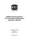
Message Area
SDM-E2/EAGLE 2
Display Area
Figure 21: Parts of the Main Program Window
Control Buttons
The Cylinders, Config, Logs, and Exit control buttons are located along the top right of the window. The Bump test and Calibration control buttons are located in the lower right of the window along with the Force Calibration selection box. The use of these control buttons and the Force Calibration selection box is described in other parts of this manual.
SDM-E2/EAGLE 2 Display Area
The large middle portion of the main program window displays SDM-E2s and EAGLE
29 • Overview of the SDM-E2 Docking Station PC Controller Program
advertisement
Related manuals
advertisement
Table of contents
- 6 Introduction
- 7 System Requirements
- 8 Specifications
- 9 About This Manual
- 9 Cautions & Safety Information
- 10 Description
- 10 AC Adapter
- 10 Single-Port AC Adapter
- 10 3-Port AC Adapter
- 11 USB Cable
- 11 Air Filter, Sample Tubing, and Check Valve
- 12 Instrument Panel
- 13 Back Panel
- 13 Power Jack
- 13 Sample Fittings
- 13 PC Connection
- 14 Control Panel
- 15 Front Panel
- 16 Hardware Setup
- 16 Hardware Assembly
- 17 Assembling a Manifold for Multiple SDM-E2 Units
- 18 Exhaust Tubing
- 20 GAS 1 Tubing
- 20 GAS 2 Tubing
- 24 Connecting Calibration Gas
- 26 EAGLE 2 and GX Type Instrument Connection
- 26 Installing the SDM-E2 Docking Station PC Controller Program
- 32 Launching the SDM-E2 Docking Station PC Controller Program
- 33 Overview of the SDM-E2 Docking Station PC Controller Program
- 33 PC Controller Program Functions
- 34 Main Program Window
- 34 Control Buttons
- 34 SDM-E2/EAGLE 2 Display Area
- 35 Program Status
- 35 Fitting Indicators
- 35 Setting Up the PC Controller Program
- 35 Setting Up the Configuration
- 40 Setting Up the SDM-E2 Display Order
- 42 Cylinders Window
- 43 Selecting a Cylinder from the Pre-Defined List
- 44 Defining New Cylinders
- 45 Connecting Instruments to the PC Controller Program
- 49 Icon View vs. Details View
- 51 Exporting an Instrument List from the Main Program Window
- 52 Instrument Placement for Bump Testing and Calibration
- 54 Automatic Bump Testing and Calibration
- 55 Bump Testing a Standard 4-Gas Instrument
- 66 Calibrating a Standard 4-Gas Instrument
- 76 Bump Testing an Instrument with Special Sensors
- 92 Calibrating and Instrument with Special Sensors
- 107 Troubleshooting
- 108 Charging an Instrument in an SDM-E
- 108 Recharging a Battery Pack After Performing a Bump Test or Calibration
- 109 Recharging a Battery Pack Without Performing any Operations
- 110 Batteries Too Drained for PC Controller Operation
- 111 Logs Button
- 115 Alarm Trend Data
- 123 Calibration Data
- 125 Event Data
- 127 Interval Trend Data
- 137 Memo Data
- 139 Bump Test Data
- 143 Deleting Data in the Logs Window
- 144 Instrument Function Menu
- 144 Open Function
- 145 Edit Function
- 145 Parameter Tab
- 152 Sensor Tab
- 153 Station & User Tab
- 159 Conversion Table Tab
- 163 PID Sensor Tab
- 169 Channel Gas Tab
- 170 Gas Name Tab
- 170 Download Function
- 170 Clear Logs Function
- 171 Power Off Function
- 171 Obtaining a Relative Response Factor
- 182 Config Window
- 182 Parameter Tab
- 183 Database Tab
- 185 Password Tab
- 186 Spare Parts List
- 190 Appendix A: Multiple Instrument Configurations
- 190 Bump Testing Multiple EAGLE 2s with Different Sensor Configurations
- 207 Calibrating Multiple EAGLE 2s with Different Sensor Configurations
- 223 Appendix B: Bump Testing and Calibrating EAGLE 2s with IR Sensors