advertisement

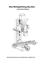
Mini Milling/Drilling Machine
Instruction Manual
Read all instructions and warning before using this tool
CONTENTS
CHAPTER1 SPECIFICATION
1-1 Machine specification
1-2 Packing list of accessories
CHAPTER2 MACHINE INSTALLATION
2-1 Fundamental locating of the machine
2-2 Preparation before operation
CHAPTER3 PREVENTION AND MAINTENANCE
3-1 Prevention and maintenance
3-2 Maintenance of cutter and taper shank
3-3 Mechanics lubrication
CHAPTER4 MACHINE STRUCTURE
4-1 External feature
4-2 Assembly and parts
CHAPTER5 MECHANISM ADJUSTMENT
5-1 Installation and removal of taper shank
5-2 Travel adjustment
5-3 Adjust tip angle of fuselage
5-4 Miter wedge adjustment
CHAPTER6 OPERATION AND NOTICE FOR USE
6-1 Method of operation
6-2 Operation attention
CHAPTER7 GENERAL SAFETY INSTRUCTION
CHAPTER8 POWER CONNECTION & ELECTRICITY
8-1 Power connection/disconnection & Operation
8-2 Electrical circuit diagram
1
Some Safety Features of this Machine
a) Purpose of this machine: This machine is designed for drilling, deep milling and face milling of small work piece with limit of size “250mm/300mm×200mm×200mm”.If the operator intend to use this machine beyond our design purpose, please contract the manufacturer or your dealer operation. b) The following items is prohibited for this machine
-operating machine without going through of manual.
-operating machine without professional training of drilling & milling work.
-operation machine beyond the design purpose and limit of this machine without gitting sufficient about safety from manufacturer or our agent.
-operating machine without making sure that every safety precaution is well according to this instruction. c) Some important safety information.
-The noise level during operation is 83 dB(A).
-The temperature rang suitable for the operation & storage of this machine is –20~+40 degree C. d) Special Warning for this machine:
-Warning! After interruption due to power failure, There exist the risk of accidentally running up. Be sure to pay attention to this risk and turn off machine as soon as machine interrupt.
-Warning! Always wear approved eye protection during operation. e) Correct handling of this machine.
-The net weight of this machine is 62Kg. It would be better to handle this machine with the help of appropriate lifting tool.
-If the operator has to handle this machine without lifting tool, be sure to make sure you can afford this weight, and handle it with care and common sense of self-protection.
2
CHAPTER 1 SPECIFICATION
This is a mini vertical milling machine with multiple functions on either face mill or drill.
There are various sizes and kinds of cutter currently. It’s easy to purchase, that can apply different to insure you work more accurate and more efficient as long as you change the cutter upon your demand.
1-1 Machine Specification
SPECIFICATION
Max.table travel
Max.cross slide
Max.spindle travel
10"/12(250/300mm)
4"/5" (100/130mm)
7" (180mm)
Spindle Speed
Taper of hole in spindle *
Drilling Capacity
End Milling Capacity
L:50-1100rpm H:120-2500rpm
MT #3 or R8
1/2" (13mm)
5/8" (16mm)
Face Milling Capacity
Machine Weight
11/8" (30mm)
GW:80Kg NW:62Kg
Remark: The item marked(*)has different choice, see the label in front of the machine or ask information to your dealer.
3
□
T-Slot Specification (mm)
T-SLOT T-NUT
1-2 Packing list of Accessories
1. large wrench S:36 1
2. Drill chuck & taper shank 1
3. Oil can 1
4. Fixing Pin 1
5. L Hex. Wrench S: 2,2.5,3,4,5,6,8 4
6. Socket head wrench D: 45-52 1
7. Double end wrench 8-10, 13-16 1
8. Drill chuck holder 1
9. Handle 3
10. T-Nut 4
11. Nut 4
12. Bolt 4
13. Fuse 8A (110V) or 5A (230V) 1
14. Draw bar 1
4
CHAPTER 2 MACHINE INSTALLATION
2-1 Fundamental Locating of the Machine
The machine should be fixed on working with four Hexagon bolts.
Please install it an appropriate location in order to demand the precision requirements of the machine.
The Selection of The Installing Location
(1) The working table should have a flat surface.
(2) Avoid the place with direct sunshine, heavy moisture and dust.
Method of Fundamental Locating
(1)Please drill 4 locating holes on working table,
The dimensions should as same as the holes on the machine’s base.
(Attention: the machine’s position, You had better consider Y-axis hand wheel will benefit later on.)
(2) Please adjust the machine to horizon and
Fix the worktable with 4 M10 bolts and nuts.
2-2 Check the Follow Items Before Switching On the Machine:
1. Remove all of fixtures which used foxing the machine when you equipped the machine.
2. Check whether the power voltage is suited to the machine.
(see label in front of the machine.)
3. Remove all obstacle which are around the machine.
4. remove anti-rust protection which were used before you fixed the machine.
5. Check the angle of the pillar and adjust the bolts to see if they are unloaded.
6. Check the chuck, chuck holder and fixing pin on spindle to make sure they are unloaded.
7. Check the High-Low speed on spindle to see if it sets on right speed.
8. Turn on the machine and check the direction of spindle rotating (clockwise).
9. Operate Longitudinal Axis (Working table),Cross Axis (Saddle seat),Vertical Axis (Fuselage) to ensure it’s in normal condition.
10. During the operation, watch out while you’re manipulating the machine.
If there is any unusual situation, stop operating and repair immediately.
5
CHAPTER 3 PREVENTION AND MAINTENANCE
3-1 Prevention And Maintenance
3-1.1 Daily Maintenance
(1) Inspect each operating part to ensure the condition of lubrication.
(2) To examine each component if the part is fixed and no other abnormal situations.
(3) Please clean and remove the obstacles around the machine in order to prevent
Machine damage and safety of the operator.
(4) Please keep the machine clean after daily use lubricate the movement parting to prevent rust.
(5) Please watch out the operation while you’re manipulating the machine.
In case that there is any unusual phenomena, please stop and repair immediately.
3-1.2 Seasonal Maintenance
(1) Please use clean cotton or soft gauze to clean each part of the machine.
(2) Please confirm whether the motion of machine’s head fixed are smooth or loosen.
(3) Check whether the spindle is over-swing.
(4) Check whether each bolt and nut is loosen.
(5) Examine the overall circuit (contact points conductor, plugs and switches…) to ensure its normal condition.
3-1.3 Seasonal Maintenance
(1) Please perform the maintenance on each level and make record.
(2) Please stop the machine before replacing the part or maintenance in order to avoid danger.
(3) Maintenance and repair showed be done regularity. If any abnormal situation occurs, stop the machine and repair immediately.
(4) If the abnormal situation is beyond the regular maintenance. Please contact our service engineer nearest to you in order to avoid further damage and safety.
3-2 Maintenance of Accessories
3-2.1 Maintenance of Cutter
(1) Use rag while install or unload the cutter to prevent the cutter falling and cause the split of blade as hurt the figures.
(2) Keep the cutter in wooden or plastic box when you don’t need it, In order to maintain the sharp blade, the cutter should be kept respectively.
(3) Pay extra attention on cutter rotating direction. Wrong rotating direction might cause sharpness and blade direction in high speed revolving, please turn off the machine, during the process, in decelerating speed, easier to it will be identify the blade direction.
(4) Put the cutter and working piece (or chuck piece) in right places before you turn on the machine. After turn on the machine, the cutter will get close to the working
6
piece and mill it.
(5) Sharpen the cutter as soon as it gets sharpness. Sharpness cutter is not only hard to do the milling work but also easy to cause damage on blade.
3-2.2 Attention Items For Accessories
(1) Please keep the taper shank clean.
(2) Please keep the taper shank and cutter in order and keep the same cutter together.
Next time when you use them ,you will feel more convenient.
(3) Draw bar and chuck have their own wrenches. For your convenience, please keep the wrenches near by the machine with inappropriate tools.
(4) Please use wrench to tight the nuts and never use other tools such as steel hammer to do so.
3-3 Mechanics Lubrication
In order to ensure the precision ,keep lubrication on contact face.
In accessories, there is an oil-can, use it to lubricate. Please inject some lubricant to all of contact face before operating.
The following are the item that needs to make lubrication on machine.
□
USE LUBRICATING OIL □ USE LUBRICATING GREASE
(1) Basement and saddle face (1) X-Axis feeding screw(saddle seat).
(2)Saddle seat and connecting strut (2) Y-Axis feeding screw(working table). slide face.
(3)Fuselage sear and connecting strut (3) Z-Axis feeding gear rack(fuselage). slide face.
(4)Fuselage and spindle box slide face.
Lubricating grease
Lubricating oil
After working, clean the work table and lubricate with a lubricate to protect the worktable.
7
CHAPTERR 4 MACHINE STRUCTURE
4-1 External Feature
8
4-2 Assembly and Part
Longitudinal(Y)Axis Cross (X)Axis
9
Vertical (Z) Axis
10
Spindle and Gear box
11
□Parts List
Item
Part Name
Q’ty
Item Part Name
003 Screw M3×8
004 Label
005
DC MOTOR 550W 83ZYT005
006 Key 3×16
009
Gasket
012 Screw M5×12
013
Rubber tray
1
010 Pinion ( 18Z)
011 Key (4×8)
1
110
Shaft
114 Cover
015
Rubber tray (7.5) 4 116
Spindle box
017 Earth-plate
018 Screw M4× 8
019 DC Motor Speed control
020
Rubber tray (24)
021 Power plug cord
022
PG-bushing with trumpet shape
023 screw M4×12
024 cover
1 121
Spacing ring
026 Switch
030 Tune up resistance
034 Screw M3×12
036 screw M5×5
101
Screw M6×25
3
2
12
138
Screw M4×8
1
1
6
1
3
2
1
1
2
1
1
1
1
4
Q’ty
4
1
1
1
2
1
1
1
1
1
1
4
1
1
1
4
1
4
1
1
1
1
2
□Parts List
Item
141 Worm
Part Name
1
Q’ty Item
209 Ruler
Part Name
142
Bar 1
143 Screw M5×8
145 Label
147 Screw M8X60
149
Steel ball φ5
150 Spring
151 Screw M6×6
152 Knob
156 Key (4×20)
157 Pinion
158 Pin
160
Handle M6×25B
162 Wedge
163 Screw M6×25
4
1
1
1
1
1
1
3
1
1
2
2
1
2
3
1
1
1
1
1
211 Screw M10×35
212 Top cover
213 Cover Nut M8
214 Washer
215 Cover
216 Internal ring
217 Supporting shank
218 Torsion spring
219 Cover
220 Bush
221 Screw M5×10
222 Spring support
223 Rotor shaft
224 Lock sleeve
225 Screw M5×6
226 Ruler
227 Fuselage
228 Cover Nut M6
229 Handle
230 Spring
231 Indicator
232 Handle block
233 Nut M24 165
Screw M8×45
166 Spindle box seat
167 Pin (8×25)
4
1
10
10
2
169 Prop
170 Shaft
201 Upper end washer
202 Screw M6×20
204 Screw M6×14
205 Wedge
207 Rivet
1
1
1
3
14
1
1
2
1
1
1
234 Big washer
235 Fuselage seat
236 Shaft
237 Key (8×12)
238
Pin (3×12)
301 Base
302 X-axis feeding screw
303
Screw seat
304 Screw M6×12
305 Dial
306 Hand wheel
307 Nut M8
308 Knob
13
3
3
1
7
3
2
1
1
1
1
1
1
1
1
1
1
1
1
1
1
1
1
1
3
1
1
1
1
1
1
2
1
2
3
1
2
Q’ty
1
3
□Parts List
Item Part Name
309 Screw M8×52
310 Dust guard cover (2)
312 Holding plate
313 Screw M6×8
314 Dust guard cover (1)
315 Holding plate (1)
316 Y-axis bearing seat
317 Guide finger
318 Thrust ball bearing 51200
319 Tie-in
320 Working table
321 Y-axis feeding screw
322 Y-axis ruler
323 Screw M5×20
324 Y-axis screw nut
325 Screw M6×10
326 Y-axis wedge
327 Saddle
328 X-axis screw M6×8
329 Cover screw M6×8
330 X-axis wedge
331 X-axis screw nut
14
1
2
1
1
1
4
1
1
1
2
2
1
2
3
2
4
1
2
8
Q’ty Item
3
1
1
1
Part Name Q’ty
CHAPTER 5 MECHANISM ADJUSTMENT
5-1 Installation and Removal of Taper shank
□
Installation
(1) Turn off the main power when you replace the cutter.
(2) Pull out the protective cover(a).
(3) Wipe the spindle and taper shank.
(4) Put the taper shake(a) into spindle sleeve. Cutter should be matted with oil cloth to keep the safety of machine and fingers.
(5) Insert fixing Pin(d) right on spindle sleeve.
(6) Use#14 open end wrench(c) to tight(clockwise) spindle draw bar(b) for fixing taper shank.
(7) Pull out the fixing pin.
(8) Install the protective cover(a).
□
Removal
(1) Turn off the main power before you replace the cutter.
(2) Pull out the protective cover(a).
(3) Insert fixing pin(d) right on spindle sleeve.
(4) Use#14 open end wrench(c) to loose (counter clockwise) the spindle draw bar(b).
(5) Knock the taper shank(g) gently by plastic hammer to loose it in spindle sleeve.
Then take off the taper shank(g).
(6) Cutter should be matted with oil cloth to keep the safety of machine and fingers.
(7) Install the protective cover(a).
※For your safety,
any adjustment on machine
should be operated
under no electricity.※
15
5-2 Travel Adjustment
Using the limit block can control the traveling box.
(1) Loose the handle(a) beside of the limit block(b).
(2) Adjust the limit block(b) in position.
(3) Tighter the handle.
(4)
Travel position can refer to the ruler on the fuselage rotary.
5-3 Adjust Tip Angle of Fuselage
(1) Turn off the main power before adjustment.
(2) Hold the fuselage by hands to avoid the fuselage
falling.
(3) Loosen the locked nut(a) with large wrench(b).
(4) Adjust the fuselage lip angle as you need.
(Max is 45
◦
both left and right)
(5) Tighten it.
5-4 Miter Wedge Adjustment
After a long –term contact motion to the machine, function error occurs owe to relative surface motion. Miter wedge act as an interface on each slide face. In order to eliminate this error this machine make use of adjusting screw making pressure between two machine parts(ex. Spindle Box and Fuselage) Adjust and keep up the contact pressure for maintain its precision.
In order to ensure the precision, the pressure between the two element needs to be adjusted appropriately because of abrasion which the machine produced the contact motion for same time(about one year).
The follow items need to make Miter Wedge pressure adjustment
1. Basement and saddle seat slide face.
2. Saddle seat and working table slide face.
3. Fuselage and connecting strut slide face.
4. Fuselage and spindle box slide face.
<Notice: Let the spindle box at the highest position when not using>
The way to adjust:
(1) Loosen the locked nuts.
(2) Adjust the foremost pressure of the miter wedge by locked nut. If necessary, please loose all adjusting screw has to be same.
(3) Tighten and loose the adjusting screw and keep in mind that the pressure of each adjusting screw has to be the same.
(4) Tighten the locked nut uniformly.
(5) When lock the locked nut, please use the #3 interior hexagonal wrench to fix the adjusting screw from rotating to cause the unbalance pressure.
(6) Please adjust the middle portion first and then go to toward the interior from two sides uniformly while you are adjusting the screw in order to ensure an uniform pressure.
16
CHAPTER 6 OPERATION AND NOTICE FOR USE
6-1 Method of Operation
□ Drilling or Deep Milling
1. According to Chp5, replacement of chuck and tool. Install appropriate adjustment and tighten it certainly.
2. Select appropriate speed level.[ATTENTION: When spindle is running, don’t
change the HIGH/LOW speed!]
3. Use press cake or fixture set the workpiece on the working table.
4. Adjust working table (Longitudinal Axis(Y)) and Saddle seat (Cross Axis(X) in position.
5. Loosen the limit block handle, adjust the blocks in position. Note don’t let tool meet the workpiece.
6. Put Adjusting tools in order and remove all obstacles which are around the machine.
7. Turn on the main power. Adjust appropriate spindle speed and drilling or deep milling.
8. Refer the rule on fuselage can know drilling or milling depth.
9. Finish working, turn off power and take the spindle to upper position.
10. Clean the machine.
□
Face Milling
1. According to Chp5,repacement of chuck and tool. Install appropriate adjustment and tighten it certainly.
2. Select appropriate speed level.[ATTENTION: When spindle is running, don’t
change the HIGH/LOW speed!]
3. Use press cake or fixture set the workpiece on the working table.
4. Adjust working table (Longitudinal Axis(Y)) and Saddle seat (Cross Axis(X) in position.
5. Release limit block on fuselage, adjust the depth of cut, then fixed.
6. Arrange all tools in proper place.
7. Turn hand wheel of working table (Y-axis)and saddle seat (X-axis) to do face milling.
8. Finishing all steps, turn off power and make spindle return to upper position, release workpiece.
9. Clean the machine.
□
Drilling or Milling Speed
Before any operation, set the spindle to a correct speed of running.
The operating speed range for working is 50 to 2500 rpm. For most part, the correct speed may consider the size of working face and the material. Generally, you can use higher speed for softer material or small holes. Use lower speed for harder material or bigger holes.
A good rule of thumb is: Small hole and the softer material , use higher speed. But don’t drill too fast (above 2300 rpm) if your workpiece is wood, you may burn it. For metal, the speed can from 50 to 2500 rpm.
17
6-2 Attend for Operation
Please attend the following items as you operate in order to ensure the operation safety and maintain the capacity of machine.
□
Inspection before turn on
1. Before turn on power, you must check the tool chuck and cutter tighter it certainly.
2. Inspect whether each machine part has loosen.
3. Check the rod of speed adjustment at correct position certainly.
4. Workpiece is fixed with press cake or fixture certainly.
5. Clean and remove the obstacles around the machine.
□
During Operation
1. Drinking alcohol or being worse spirited is absolutely forbidden to operate the machine.
2. Wearing gloves or necktie is absolutely forbidden to operate the machine.
3. Select and install appropriate cutter, no loosen.
4. The machine will shaking as follows condition: a. The depth of cut is too deep. b. The feeding speed is too fast. c. The rotation speed is too fast. d. The machine and stock plane is not fixed firmly. e. The vice and workpiece is not fixed firmly.
□
Protection and Maintenance
1. Please perform the maintenance on each level and make a record.
2. Please turn off the power perform maintenance or projection.
3. Please inform our dealer to assign professional person to deal with the action beyond extent of individual and protection.
18
CHAPTER 7 GENERAL SAFETY INSTRUCTION
Warning !
When using electric tools, basic safety precautions should always be followed to reduce the risk of fire, electric shock and personal injury, including the following. Read all these instructions before operating this product and save these instructions.
1. Keep work area clean.
-Cluttered areas benches invite injuries.
2. Consider work area environment.
-Do not expose power to rain. Do not use power tools in damp or wet locations. Keep work area well lit. do not use power tools where there is risk to cause fire or explosion.
3. Guard against electric shock.
-Avoid body contact with earthed or grounded surfaces ( e.g. pipes, radiators, ranges, refrigerators.)
4. Keep children away.
-Do not let visitors touch the tool or extension code. All visitor should be kept away from work area.
5. Store idle tools.
-When not in use, tools should be stored in a dry, high or locked up place, out of reach of children.
6. Do not force the tools.
-It will do the job better and safer at the rate for which it was intended.
7. Use the right tools.
-Do not force small tools or attachments to do the job of a heavy duty tool. Do not use tools for purposes not intended; for example, do not use circular saws to cut three limbs or logs.
8. Dress properly.
-Do not wear loose clothing or jewelry, they can be caught in moving parts. Rubber gloves and non-skid footwear are recommended when working outdoors. Wear protecting hair covering to contain long hair.
9. Uses safety glasses.
-Also use face or dust mask if the cutting operation is dusty.
10. Connect dust extraction equipment.
-If devices are provided for the connection of extraction and collection facilities, ensure these are connected and properly used.
11. Do not abuse the cord.
-Never carry the tool by cord or hand it to disconnect it from the socket, keep the cord away from heat, oil and sharp edges.
12. Secure work.
-Use clamp or a voice to hold the work. It is start than using your hand and it frees both hands to operate the tool.
13. Do not overreach.
-Keep proper footing and balance at all times.
14. Maintain tools with care.
-Keep cutting tool sharp and clean for better and safer performance. Follow instructions for
19
lubrication and changing accessories. Inspect tool cord periodically and if damaged have it repaired by an authorized serviced facility. Inspect extension cords periodically and replace, if damage keep handle dry, clean and free from oil and grease.
15. Disconnect tools.
-When not in use , before servicing and when changing accessories such as blade, bits and cutter.
16. Remove adjusting keys and wrenches.
-From the habit of checking to see that keys and adjusting wenches are removed from the tool before turning it on.
17. Avoid unintentional starting.
-Do not carry a plugged-in tool with a finger on the switch. Ensure switch. Ensure switch is off when plugging in.
18. Use outdoor extension leads.
-When tool is used outdoors, use only extension cords intended for outdoor use.
19. Stay alert.
-Watch what you are doing. Use common sense. Do not operate tool when you are tired.
20. Check damaged parts.
-Before further use of the tool, a guard or other part that is damaged should be carefully checked to determine that it will operate properly and perform its intended function. Check for alignment of moving parts, free running of moving parts, breakage of parts, mounting and any other conditions that may affect its operation, A guard or other part is damaged should be properly repaired or replaced by an authorized service center unless otherwise indicated in this instruction manual. Have defective switches replaced by an authorized service facility. Do not use the tool if the switch does not turn it on and off.
21. Warning.
-The use of any accessory or attachment, other than those recommended in this instruction manual, may present a risk of personal injury.
22. Have your tool repaired by a qualified person.
-This electric tool is in accordance with the relevant safety requirements. Repairs should only be carried out by qualified persons using original spare parts, otherwise this may result in considerable danger to the user.
20
CHAPTER 8 POWER CONNECTION & ELECTRICITY
8-1 Power Connection/disconnection & Operation
1. The connection, disconnection, and grounding is carried out through the plug, equipped on the machine. For the safety reason, Do not change this plug into any the other type in any situation.
2. For the protection of control device, we recommended the operator to supply a fuse with current rating and the total length between fuse and connection terminal shall be according
“ EXTENSION LEAD CHART”
EXTENSION LEAD CHART
Ampere rating
Extension Cable length
3A
7.5m 0.75
6A
Wire Size mm
0.75
10A
2
13A
15m 0.75
22.5m 0.75
0.75
0.75
3. The
30m 0.75
45.5m 0.75
0.75
1.25
exact power source is110V or 230V, single phase, 50/60Hz. (see label in front of the machine)
4. Make sure the Emergency Stop switch(A) (left beside the electrical box) is in “OFF” position before plugging in cord.
5. Disconnect tools from power source with plug before servicing and when changing accessories such as guard.
Operation
1. INITIAL START
Taking all precautions stated, set the
HIGH-LOW range lever to Low. Insert the electric plug into the socket.
Put the Motor power switch(E) to“I”, then release the Emergency Stop
Switch(A) by pushing down on the red knob slightly and pushing it up, as indicated by the arrow on the top of the red knob.
Switch on the machine by GENTLY turning the Variable Speed Control.
Knob(D), clockwise. A click will be heard as motor power is turn on, but the spindle will not rotate until the knob is turning clockwise a little further. Speed will increase progressively the further the knob is turn. Run for a total of 5 minutes during which time gradually increase spindle speed to its maximum. Run for at least 2 minutes at this speed before stopping the machine and disconnecting from the mains supply.
21
Check that all components are still secure and working freely and correctly.
Check also to ensure the mounting are secure.
Repeat the procedure at HIGH range setting.
CAUTION: NEVER attempt to change from HIGH to LOW range with the machine running.
2. STARTING UNDER NORMAL CONDITIONS
1) Take all necessary precautions previously stated, and ensure the workpiece is fixed firmly.
2) Set the speed range control level to HIGH or LOW as required.
3) Proceed to start the machine as described in Section 1. Above.
ATTENTION: The power supply system of this machine has an auto over-load protective function. If the feeding is too fast or drilling is too deep, the system will stop working, a yellow lamp(B) lights. Just turn off the Variable Speed control(D) and then turn on again.
The system will work again and then the yellow lamp will off automatically.
22
8-2 Electrical Circuit Diagram
23
advertisement
